In every hydraulic system, precise control of hydraulic oil flow and direction is essential for achieving efficient, smooth, and reliable operation. At the heart of this control lies the hydraulic control valve—a critical component that translates mechanical or electronic input into controlled movement. Whether it’s powering heavy machinery, steering agricultural equipment, or managing precision motion in industrial automation, hydraulic valves ensure that oil is delivered exactly where and when it’s needed. Understanding how these valves regulate flow and direction helps optimize system performance, minimize energy loss, and extend equipment lifespan.
What Is a Hydraulic Control Valve in Flow and Direction Regulation?
A hydraulic control valve is a mechanical device designed to regulate both the flow rate and direction of hydraulic oil.
Its main functions in a hydraulic system include:
Directing hydraulic oil to the correct actuator, such as a cylinder or motor
Controlling actuator speed by adjusting oil flow rate
Maintaining system pressure while preventing overload
Essentially, the valve translates operator commands or automated signals into precise mechanical actions by controlling hydraulic oil pathways. This ensures actuators perform exactly as required.

How Hydraulic Valves Control Flow in a Hydraulic System
Hydraulic control valves manage hydraulic oil flow by opening, closing, or partially obstructing internal passages. Flow regulation directly affects actuator speed and energy transfer in the system.
Flow control methods include:
Throttle valves: Small orifices restrict oil flow, slowing actuator movement
Needle valves: Adjustable needles provide fine-tuned flow control
Proportional valves: Electronically controlled to vary flow dynamically
In operation, oil enters the valve from the pump and passes through the spool or poppet. By adjusting the valve opening, the hydraulic valve controls how fast oil reaches the actuator. This mechanism allows for precise control of linear or rotary motion in the hydraulic system.
| Flow Control Method | Working Principle | Effect on Hydraulic System |
| Throttle Valve | Uses a small orifice to restrict oil flow | Slows actuator movement and controls speed precisely |
| Needle Valve | Adjustable needle allows gradual change in passage area | Provides fine-tuned flow control and smooth motion |
| Proportional Valve | Electronically adjusts valve opening in response to control signals | Enables dynamic and precise hydraulic flow regulation across varying loads |
How Hydraulic Valves Direct Hydraulic Oil
Directional control valves (DCVs) determine the path hydraulic oil takes in a hydraulic system. By shifting the spool inside the valve, oil is sent to either side of a cylinder or into a motor.
Types of directional control valves:
2-way valves: Simple on/off routing of oil
3-way valves: Direct oil from pump to actuator and back to tank
4-way valves: Control double-acting cylinders, sending oil to either side while connecting the opposite side to the return line
By selecting the correct DCV type, operators can control the motion direction of actuators and sequence multiple operations in a hydraulic system.
Spool vs Poppet Mechanisms in Oil Flow and Direction Control
Spool valves: Cylindrical spools slide within the valve body to align or block ports. Flow rate and direction are controlled by moving the spool precisely.
Poppet valves: Conical or ball-shaped elements block or allow oil flow based on position. They provide rapid on/off control with minimal leakage.
Both mechanisms allow hydraulic valves to regulate flow and direction accurately, ensuring smooth actuator movement in the hydraulic system.
Actuation Methods Affecting Flow and Direction
In a hydraulic system, the way a hydraulic valve is actuated determines how precisely it can control the flow and direction of hydraulic oil. Different actuation methods offer varying levels of control, response time, and automation, making them suitable for different industrial or mobile applications.
Manual Actuation
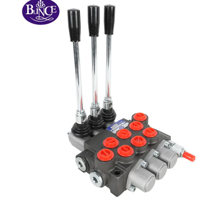
Manual actuation uses levers or handles to move the valve spool, changing how hydraulic oil flows through the circuit. It’s a simple, mechanical method often used in basic hydraulic systems like agricultural machinery or workshop presses. Although it lacks automation, it provides direct operator feedback and reliability in low-demand environments.
Solenoid Actuation
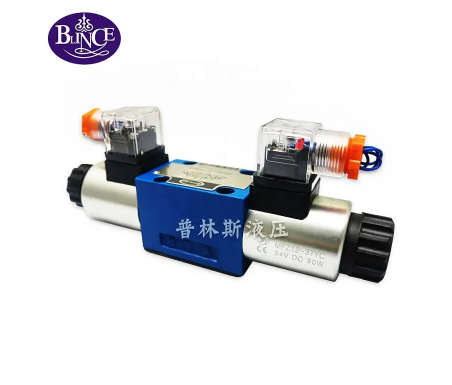
In solenoid actuation, electromagnetic coils generate a magnetic field to shift the valve spool automatically. This design enables remote or automated control of hydraulic valves, making it ideal for modern industrial equipment where precision and quick response are critical. By integrating sensors and controllers, solenoid-actuated valves can dynamically adjust oil flow and direction based on system demands.
Pilot-Operated Actuation
Pilot-operated actuation employs a small pilot valve to control a larger main valve. This setup allows fine control of hydraulic oil flow and direction using minimal input force. It’s especially valuable in high-pressure hydraulic systems, where it enhances control accuracy while reducing operator effort. Pilot systems are common in heavy machinery, injection molding equipment, and advanced motion control applications.

Flow and Direction Control in Valve vs Pump-Controlled Systems
Valve-controlled systems:
Spools or poppets regulate actuator speed by controlling oil flow
Excess oil may return to the tank through bypass, slightly reducing efficiency
Best for variable-speed tasks where precise control is less critical
Pump-controlled systems:
Variable displacement pumps adjust oil supply to actuators directly
Reduces the number of valves and pipeline complexity
Provides energy-efficient flow regulation and directional control in high-precision hydraulic systems
| Feature | Valve-Controlled | Pump-Controlled |
| Flow regulation | Spool/poppet control | Pump displacement |
| Direction control | Spool movement | Pump output routing |
| Efficiency | Moderate | High |
| Complexity | Medium | Medium |
| Best for | Variable speed, lower precision | Steady speed, high precision |
Key Components in Controlling Hydraulic Oil
Valve body: Channels oil and supports internal components
Spool/poppet: Adjusts oil paths to regulate flow and direction
Actuator: Moves the spool/poppet; manual, solenoid, or pilot-operated
Seals and springs: Maintain leak-free operation and neutral position
Sensors (optional): Provide feedback for automated control in modern hydraulic systems
These components ensure that hydraulic valves can precisely regulate oil flow and direction to achieve desired actuator motion.
Common Challenges in Flow and Direction Regulation
In every hydraulic system, maintaining stable flow and direction control is essential for efficient operation. However, several challenges can disrupt this balance, affecting actuator performance and overall reliability.
Leakage
One of the most common issues in a hydraulic valve is leakage. Worn or damaged seals allow hydraulic oil to escape, leading to reduced flow efficiency and lower system pressure. Over time, even small leaks can cause significant energy loss and temperature rise in the hydraulic system.
Contamination
Dirt, metal particles, or other contaminants in hydraulic oil can block valve passages, restrict flow, or even jam valve spools. This contamination interferes with the hydraulic valve’s ability to direct oil accurately, resulting in sluggish actuator response or erratic motion. Using quality filtration and clean hydraulic fluids helps prevent this problem.
Pressure Fluctuations
Pressure instability is another critical challenge. Rapid pressure changes can cause inconsistent oil delivery to actuators, leading to uneven movement or loss of control. Proper system calibration, use of accumulators, and pressure-compensated hydraulic valves help minimize these fluctuations and maintain smooth operation.
Faulty Actuators
Whether manual, solenoid, or pilot-operated, faulty actuators can disrupt oil flow regulation. When the actuator fails to shift the valve spool properly, hydraulic oil cannot be routed correctly within the hydraulic system. Regular inspection, lubrication, and timely replacement of worn components ensure reliable valve performance.
Applications Focused on Flow and Direction Control
Industrial Machinery
In presses, injection molding machines, and material handling systems, hydraulic valves regulate oil flow to control clamping, pressing, and lifting motions. Stable valve operation ensures smooth production cycles and consistent output.
Mobile Equipment
Construction and mining equipment—such as excavators, loaders, and cranes—rely on hydraulic systems to power heavy-duty lifting, pushing, and rotating operations. Valves control oil routing to multiple actuators, allowing operators to perform complex, synchronized movements.
Agriculture
Tractors, harvesters, and irrigation machinery use hydraulic valves to direct oil to attachments like plows or loaders. Controlled oil flow enables accurate lifting, steering, and motion adjustment, improving efficiency in farming tasks.
Aerospace and Marine Systems
Aircraft landing gear, flight control surfaces, and marine steering systems all depend on hydraulic valves for precise motion control. Here, reliability is paramount—valves must deliver consistent oil direction and flow even under high pressure and extreme temperatures.

Modern Advances in Hydraulic Valve Flow and Direction Control
In recent years, advancements in hydraulic valve technology have transformed how hydraulic systems regulate the flow and direction of hydraulic oil. These innovations enhance system precision, stability, and efficiency—meeting the growing demands of modern industry and automation.
Proportional and Servo Valves
Proportional and servo valves represent a major leap in hydraulic control. Unlike traditional on/off valves, they allow smooth and continuous adjustment of oil flow and direction. By electronically controlling the valve spool’s position, these valves achieve precise actuator movement, which is crucial in robotics, injection molding, and aerospace systems. They help the hydraulic system respond instantly to varying load conditions, improving accuracy and responsiveness.
Pressure- and Temperature-Compensated Valves
Changes in pressure and temperature often affect oil viscosity and flow characteristics. Pressure- and temperature-compensated hydraulic valves automatically adjust to these fluctuations, ensuring consistent performance even when operating conditions vary. This self-regulating behavior minimizes flow instability, reduces energy loss, and helps maintain steady actuator speed, especially in systems running under heavy or dynamic loads.
Smart Hydraulic Valves
Smart technology has entered the hydraulic valve industry, introducing sensors and microcontrollers capable of monitoring real-time oil flow, pressure, and direction. These smart hydraulic valves can automatically make adjustments to optimize performance and detect early signs of wear or contamination. By integrating feedback loops, they enhance accuracy and minimize downtime, creating a more adaptive and intelligent hydraulic system.
Industry 4.0 Integration
The integration of hydraulic valves into Industry 4.0 networks brings real-time monitoring, predictive maintenance, and data-driven optimization to the forefront. Connected valves transmit operational data to central control systems, allowing engineers to track performance trends and predict component failures before they occur. This digital transformation makes hydraulic systems smarter, safer, and more energy-efficient, paving the way for next-generation automation and industrial control.
FAQ
1. What is the main function of a hydraulic control valve?
A hydraulic control valve regulates the flow rate and direction of hydraulic oil within a hydraulic system, ensuring actuators like cylinders and motors operate precisely and efficiently.
2. How do hydraulic valves control oil flow?
Hydraulic valves control oil flow by opening, closing, or partially restricting internal passages. This determines how much oil reaches the actuator, directly affecting its speed and force.
3. What types of valves are used for flow control?
Common flow control valves include throttle valves, needle valves, and proportional valves, each offering different levels of precision and adjustability.
4. How do directional control valves work?
Directional control valves (DCVs) determine the path hydraulic oil takes by shifting internal spools or poppets. This directs oil to either side of an actuator, controlling its motion direction.
5. How does contamination affect hydraulic flow control?
Contamination from dirt or metal particles can block valve passages or jam the spool, leading to unstable flow, erratic actuator movement, and potential valve damage.
Conclusion
Effective flow and direction control is the foundation of a high-performance hydraulic system. From manual and solenoid-actuated valves to advanced proportional and smart valve technologies, each innovation enhances precision, efficiency, and system safety. As industries move toward smarter and more connected automation, the importance of reliable hydraulic control continues to grow.
For high-quality hydraulic valves and control solutions, Dongguan Blince Machinery & Electronics Co., Ltd. offers professional expertise and durable products designed to meet global standards. With years of experience in hydraulic technology, Blince delivers customized solutions that ensure your hydraulic systems perform at their best—efficient, stable, and built for long-term reliability.


