Hydraulic symbols function as the universal “language” of fluid power diagrams. They stand in for pumps, motors, valves, cylinders, connections, and control elements — allowing engineers across different regions and disciplines to understand a hydraulic circuit at a glance. In this guide, you will learn the major hydraulic symbols, how to read them, and how they are used in practical schematics.
Why Hydraulic Symbols Matter
Universal Communication
Standardized symbols (such as per ISO 1219) enable engineers around the world to interpret hydraulic diagrams consistently.
Simplification of Complex Systems
Rather than writing out full component names and descriptions, symbols compress functional information into concise visual form.
Fault Diagnosis and Troubleshooting
When you see a hydraulic schematic, understanding the symbols helps you trace the flow path, detect anomalies, and locate problematic components.
Design and Simulation
In CAD, simulation tools, and system integration, hydraulic symbols provide a bridge between concept and reality.
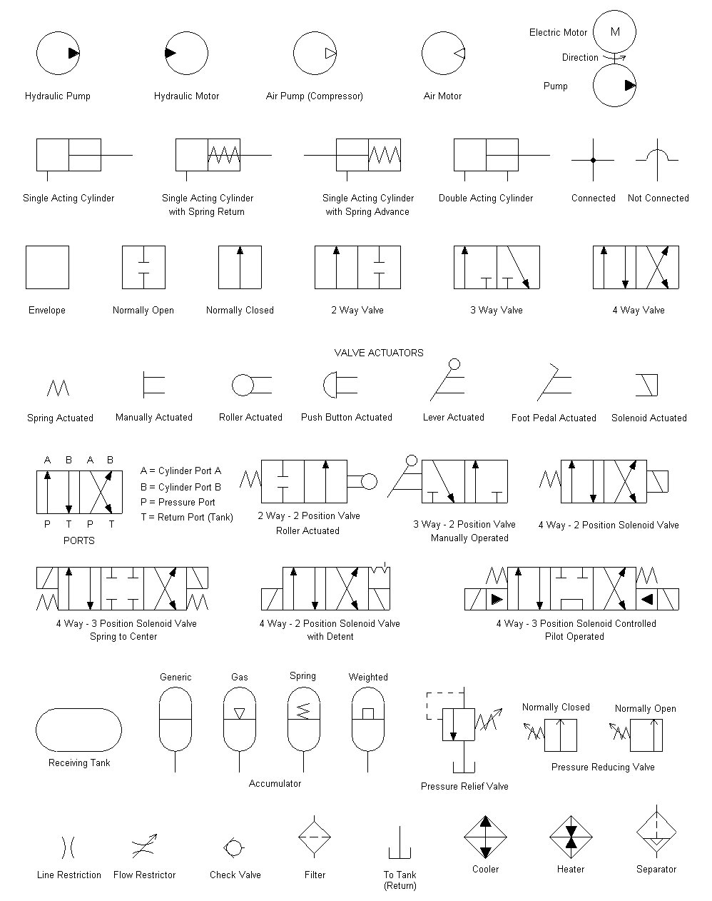
Core Symbolic Elements & Notation
Before diving into component symbols, here are fundamental elements you will frequently encounter:
| Symbol Element | Meaning / Use | Identifying Feature |
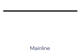
| Solid line | Main hydraulic path / pressure flow | Continuous, unbroken |
| Dashed / dotted line | Pilot/control line, signal, drain | Broken / dashed pattern |
| Dash-dot / dot-dash | Enclosure, casing boundaries | Often around groups of symbols |
| Wave / zigzag / spring line | Spring or biasing force | Symbolizes mechanical return or compression |
| Diamond / rhombus | Regulating / conditioning device | Often stands for filters, regulators |
| Circle / semi-circle | Rotational components / reservoir | Full circle for pumps/motors, semi for tank |
These basic elements form the building blocks of more complex symbols.
Key Component Symbols
Pumps
Pumps convert mechanical energy into fluid pressure and flow.
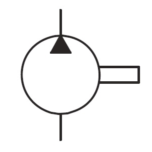
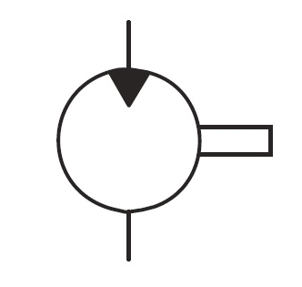
Fixed Displacement, Unidirectional Pump
A circle with a solid filled triangle arrow pointing outward (indicating fluid output direction).

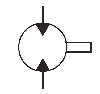
Bi-directional Fixed Pump
Two opposing arrows inside the circle, representing ability to draw fluid from either side.
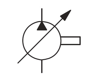
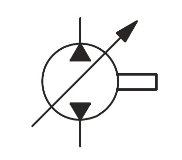
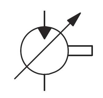
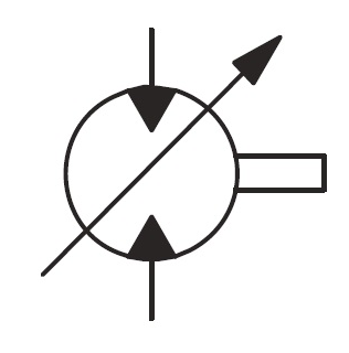
Variable Displacement Pump
The circle is intersected by a variable or adjustable arrow, indicating its output can be changed.
Pressure-Compensated / Load-Sensing Pump
The base pump symbol augmented with control circuitry — e.g., springs, pilot lines, control pistons — to regulate displacement under varying loads.
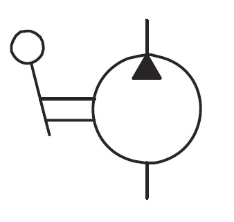
Manual Pump
Includes an additional “hand” or lever icon to indicate manual operation.
Note: The symbolic representation does not distinguish by type (gear, vane, piston), but rather by functional attributes (fixed vs variable, unidirectional vs bidirectional).
Hydraulic Motors / Rotary Actuators
Hydraulic motors convert fluid energy back into rotational mechanical motion.
Unidirectional Fixed Displacement Motor
A circle with a solid triangle pointing inward (indicating fluid input).
Unidirectional Variable Displacement Motor
Opposing arrows inside circle, denoting the motor can run in either direction.
Variable Displacement Bi-rotational Motor
A modifiable arrow through the symbol indicates adjustability of displacement or speed.
Combined Pump-Motor Units
A symbol combining both pump and motor characteristics, often used in systems with energy recovery or reversible drive modes.
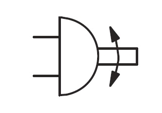
Angular / Partial Rotation Actuator
Similar to a motor but restricted to limited angles rather than full rotations.
Symbols often include shafts, rotation arrows, and control lines for pilot or displacement features.
Cylinders (Linear Actuators)
Cylinders deliver force in a linear motion.
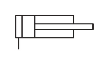
Single-Acting Cylinder
One side powered; the return may use a spring, gravity, or external force. A spring is often shown via a zigzag line.
Double-Acting Cylinder
Can be powered from both ends.
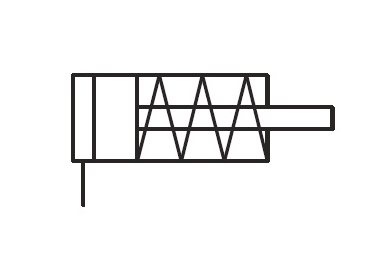
Single-acting Cylinder with Spring Symbol
Includes additional symbols (throttling, narrowed port) to slow the piston near the stroke end.

Double-acting Cylinder with a Double Rod
Depicted by nested cylinder shapes, indicating multiple sliding stages.

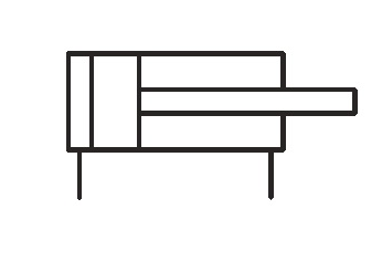
Double-acting Cylinder with One Cushioned Side
This hydraulic cylinder symbol has only one bar unlike the double-cushioned one. As such, this cylinder can absorb a significant impact on one side.
The symbols may vary in style (e.g. wider piston bodies, rectangular rod representations) depending on the drafting convention.
Valves — The Control Center
Valves orchestrate how fluid flows, in which direction, and under what constraints.
Directional Control Valves (DCV)
Represented by multiple adjacent boxes (each a spool position) with arrows showing possible flow paths.

Pressure Control Valves
Such as relief, reducing, or sequence valves. These often include spring symbols, control ports, and pilot lines.

Flow Control / Throttle Valves
Represented by adjustable arrows or orifice symbols to indicate variable flow restriction.

Check Valves / One-Way Valves
Arrows or ball-seat icons showing flow permitted in one direction, blocked in the other.

Pilot-Operated Valves
The primary symbol plus additional dashed lines or pilot control ports indicating remote actuation.
Other specialized valves include pressure-compensated flow valves, load-sensing valves, and proportional valves.
Accessories & Connections
Supporting elements and pipe connections complete the system:
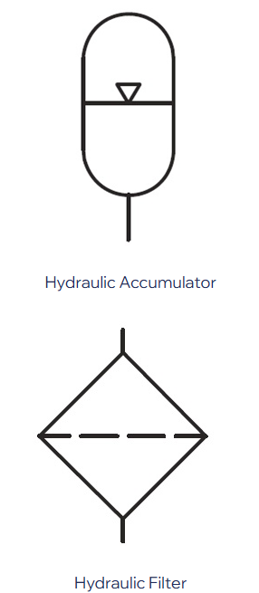
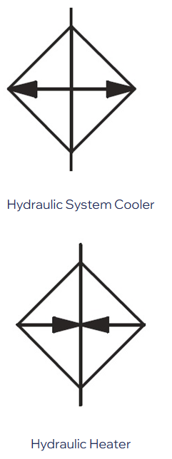
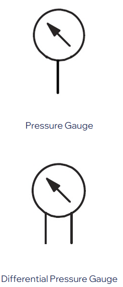
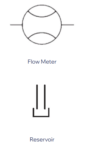
Accumulators, filters, coolers, heaters, gauges, reservoirs
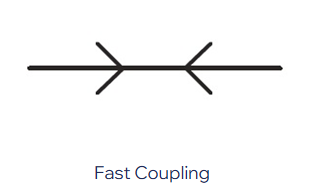
Junctions, intersections, crossovers, flexible hoses, quick couplings
Return lines, tank lines, branch lines
Connection points or nodes (represented by dots or junction symbols)
While simple in isolation, these symbols are essential to the clarity and completeness of a hydraulic circuit.
How to Read a Hydraulic Schematic — Step by Step
Locate the Power Source (Pump / Reservoir).
Begin where hydraulic energy is generated.
Trace the Flow Path.
Follow solid lines, branches, directional valves, and check valves toward actuators.
Identify Control Circuits.
Recognize dashed or dotted lines indicating pilot or signal control.
Spot Actuators (Cylinders / Motors).
Observe how they connect to valves and what directions or controls they respond to.
Interpret Control Mechanisms.
E.g. compensators, springs, throttle orifices, pilot ports — understand how they modulate pressure or flow.
Check Return or Drain Routes.
Ensure used fluid is returned properly to the reservoir or tank.
Note Labels, Ports, and Settings.
Ports (P, T, A, B etc.), adjustment ranges, pressure setting notations all provide key data.
Be Flexible with Variants.
Designers may alter or simplify symbols — adaptability and familiarity with standard forms are helpful.
Frequently Asked Questions (FAQ)
Q1: What standard governs hydraulic symbols?
A: The ISO 1219 series is widely accepted internationally for hydraulic symbol standards. The ANSI standard is sometimes used in the U.S. and may vary slightly in representation.
Q2: How do I tell if a symbol is a pump or a motor?
A: Pump symbols typically have an arrow pointing outward from the circle (indicating output flow), while motor symbols have arrows pointing inward (indicating fluid input). In reversible or combined units, arrows may go both ways, and you must interpret via context.
Q3: Does a variable arrow always mean the device is variable displacement?
A: Usually yes — a variable arrow denotes adjustability. But always check for control lines, compensator or pilot circuitry to confirm the device’s actual function.
Q4: Can hydraulic symbols be simplified or modified in drawings?
A: Yes. Designers may simplify for readability or space, but core meaning usually follows standard conventions. Be familiar with variant forms to ensure you interpret them correctly.
Q5: What’s the best way to memorize hydraulic symbols?
A: Start with the most common (pump, cylinder, valve) and practice reading real hydraulic diagrams. Create a personal reference sheet and gradually add more symbols.
Q6: Can hydraulic symbols represent all design details?
A: Symbols show function — direction, adjustability, control methods. But quantitative data (size, flow rate, efficiency) is usually given in annotations, tables, or specifications separate from the symbol.


