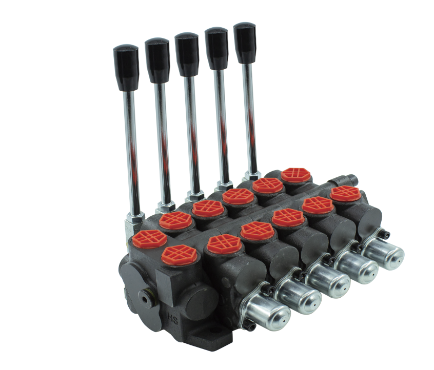
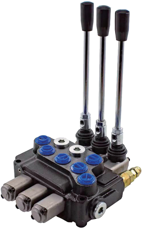
Hydraulics might sound like a subject only engineers get excited about, but guess what? It plays a huge role in our everyday machines. Ever seen an excavator move its giant arm? That's hydraulics in action. And behind that smooth movement lies a clever little component: the directional control valve. Let me take you through it in a way that's easy to understand
1. What Is a Hydraulic Directional Control Valve?
Directional control valves (DCVs) are critical components in hydraulic systems, designed to precisely manage the flow path of hydraulic fluid. Their core function is to control the direction, start, and stop of actuator movement (such as hydraulic cylinders or motors) by acting as a switchable flow-directing mechanism.
Core Functions & Operating Principle:
Flow Path Control & Directional Switching: DCVs operate by altering internal flow passages. They direct fluid from the pump (pressure source) to specific actuator ports and return fluid from the actuator to the tank (return line). This precise switching of flow paths (e.g., directing fluid to the rodless or rod end of a cylinder) directly determines the actuator's movement direction (e.g., hydraulic cylinder extension or retraction).
Actuator Movement Control: By changing the fluid direction, DCVs enable operators to start, stop, and instantly reverse the motion of actuators.
Pressure Management (Auxiliary Function): Certain DCV designs or applications can indirectly assist in managing system pressure by directing fluid from specific lines to the tank or a relief valve.
Classification:
Directional control valves are primarily categorized into three main types:
Hydraulic Check Valves: Permit fluid flow in one direction only.
Directional Spool Valves: Utilize a sliding spool within a bore to shift and connect/disconnect flow paths. This is the most common design.
Poppet Valves (Seat-Type Directional Valves): Utilize sealing elements (poppets, balls, discs) that open or close against seats to control flow paths.
2.How Directional Control Valves Work
Directional Control Valves (DCVs) are central to hydraulic systems, precisely managing fluid flow direction and on/off states in hydraulic lines to achieve several critical functions. Their primary role is to direct fluid, channeling hydraulic oil from the pump to actuators (such as extending/retracting hydraulic cylinders or rotating motors forward/backward) or guiding return oil from actuators back to the tank, thereby directly controlling the motion direction of the executive components.
They also possess flow blocking capabilities, allowing specific flow paths to be shut off during localized maintenance or functional deactivation. This isolates system subunits, preventing complete system shutdowns and significantly improving maintainability. For efficient standby management, valves typically maintain a neutral position, where the fluid remains static and ready, only activating the flow path upon receiving an operational command.
The working principle of a valve is based on dynamic spool switching. When an operation is required, the DCV triggers an instantaneous position switch (e.g., fully open to fully closed) via manual, automatic, or pre-set cycle activation. This causes the fluid to rapidly accelerate or decelerate, directly driving the actuator to start or stop. If a proportional valve is used, the flow is smoothly regulated through gradual opening modulation, achieving flexible acceleration and deceleration control of the actuator. After the operation is complete, the valve automatically returns to its neutral position, completing the "standby → activation → reset" work cycle.
In terms of structural design, the simplest DCV is a two-way valve, equipped with only an inlet and an outlet port, providing basic on-off functionality through mechanical opening and closing (similar in principle to a water faucet). When selecting a DCV, three key parameters must be carefully considered: the number of fluid ports determines the scale of pipeline connections (e.g., a 2-way valve corresponds to two ports); the number of valve positions defines the complexity of flow path configurations (for instance, a 3-position valve offers multiple paths like forward-neutral-reverse); and the pressure rating must strictly match the system's operating pressure curve to ensure reliability.

3.The Role of Pressure Lines and Return Lines
Pressure line (P): Delivers fluid from the pump
Return line (T): Sends used fluid back to the tank
Working lines (A & B): Carry fluid to/from the actuator
The valve connects these in different ways to move the machine.
4.Operational Control and Significance of Directional Control Valves
Directional control valves (DCVs) offer diverse actuation and control methods tailored to specific application requirements. The core actuation options include:
Solenoid Actuation: Utilizes electromagnetic force (generated by components like coils, armatures, or plungers) for precise and reliable valve control.
Manual Actuation: Employs direct human intervention (e.g., hand levers or foot pedals) for straightforward operation in suitable applications.
Mechanical Actuation: Relies on applied mechanical force (e.g., via cams, levers, or rollers) to shift the valve.
Pneumatic Actuation: Uses compressed air to generate the force needed for rapid and efficient valve shifting.
Hydraulic Actuation: Applies hydraulic control pressure to move the valve spool, enabling powerful and precise control.
Critical Position Control Functions:
Spring Return: Ensures the valve automatically returns to a designated default position (e.g., neutral) upon removal of the actuating force. This is essential for safety, predictable system behavior, and precise flow management.
Detented Operation (Position Holding): Utilizes a mechanical latching mechanism to maintain the valve securely in its shifted position even after the actuating force is removed. This is vital for applications requiring stable, long-term valve positioning to ensure consistent system function.

5.Operational Control and Significance of Directional Control Valves
Directional control valves (DCVs) offer diverse actuation and control methods tailored to specific application requirements. The core actuation options include:
Solenoid Actuation: Utilizes electromagnetic force (generated by components like coils, armatures, or plungers) for precise and reliable valve control.
Manual Actuation: Employs direct human intervention (e.g., hand levers or foot pedals) for straightforward operation in suitable applications.
Mechanical Actuation: Relies on applied mechanical force (e.g., via cams, levers, or rollers) to shift the valve.
Pneumatic Actuation: Uses compressed air to generate the force needed for rapid and efficient valve shifting.
Hydraulic Actuation: Applies hydraulic control pressure to move the valve spool, enabling powerful and precise control.
Critical Position Control Functions:
Spring Return: Ensures the valve automatically returns to a designated default position (e.g., neutral) upon removal of the actuating force. This is essential for safety, predictable system behavior, and precise flow management.
Detented Operation (Position Holding): Utilizes a mechanical latching mechanism to maintain the valve securely in its shifted position even after the actuating force is removed. This is vital for applications requiring stable, long-term valve positioning to ensure consistent system function.
6.Selecting the Right Directional Control Valve
Choosing the appropriate directional control valve (DCV) is crucial for optimizing your hydraulic system's performance. DCVs are categorized by a range of essential characteristics, ensuring you can find the perfect fit for your specific application. These characteristics include:
Maximum Flow and Pressure Ratings: These specify the maximum flow rate (how much fluid can pass through) and the maximum rated working pressure (the highest pressure the valve can safely handle during operation). These two factors are paramount as they directly relate to the power and efficiency your system can achieve. Exceeding these limits can lead to system failure and safety hazards.
Fluid Path Configuration: This describes how fluid can flow through the valve.
A check valve, for instance, is a type of 2-way, 2-position valve. It's typically driven by line pressure, allowing fluid to flow freely in one direction but completely blocking flow in the opposite direction. Think of it like a one-way gate for your hydraulic fluid.
A shuttle valve is a common example of a 3-way, 2-position valve. It intelligently allows flow from two different input ports to be directed to a single common output circuit. This is particularly useful when you need to select between two different pressure signals to control an actuator.
Number of Positions: DCVs typically have two or three positions.
A two-position valve usually offers an "on" and "off" state, or perhaps "forward" and "reverse."
A three-position valve commonly provides more nuanced control, such as "forward," "neutral," and "reverse." The neutral position is often vital for allowing an actuator to hold its position or to de-energize the system without completely shutting it down.
Number of Ports: This refers to the number of distinct fluid pathways where fluid can enter or exit the valve. A common example is a 4-port, 3-position valve often used to control double-acting hydraulic cylinders (one port for pressure in, one for return from each side of the cylinder, and a tank line).
Actuation Method (Drive): This defines how the valve is shifted or cycled between its different positions. Common actuation methods include:
Manual: Operated by hand, levers, or foot pedals.
Solenoid: Electrically actuated, common for automated systems.
Hydraulic/Pneumatic Pilot: Controlled by a smaller hydraulic or pneumatic signal.
Mechanical: Actuated by cams, rollers, or other mechanical linkages.
AQs
1. Can one directional valve control multiple cylinders?
Not effectively. Each cylinder usually needs its own valve to avoid cross-interference.
2. What’s the difference between open center and closed center valves?
Open center allows pump flow to go directly to the tank in neutral. Closed center blocks all ports, holding pressure.
3. Why use a 3-position valve instead of a 2-position?
The neutral (middle) position allows for safer operation and energy saving.
4. Can I use a DCV on a hydraulic motor?
Yes, but make sure the valve matches the motor's flow and pressure specs.
5. How do I know my valve is malfunctioning?
If actuators stop responding or move erratically, the valve might be blocked, leaking, or stuck.


