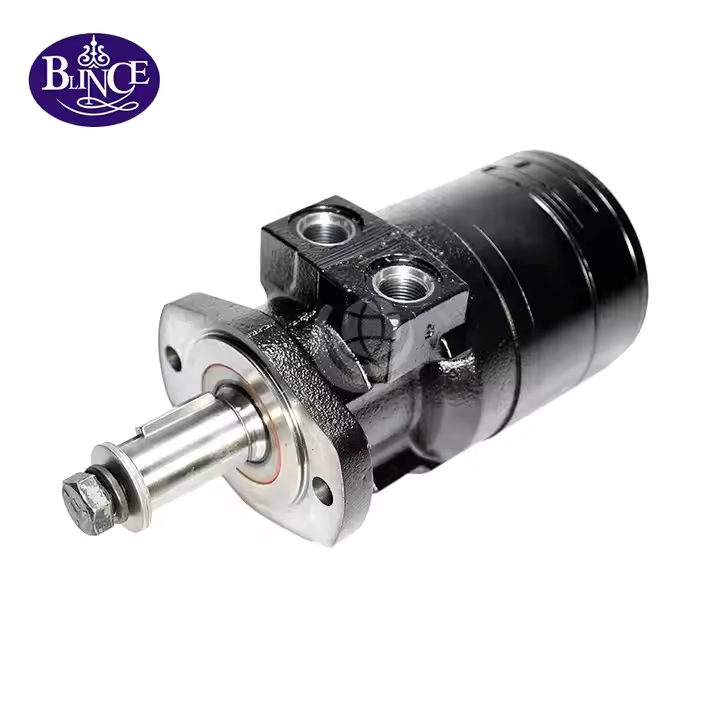
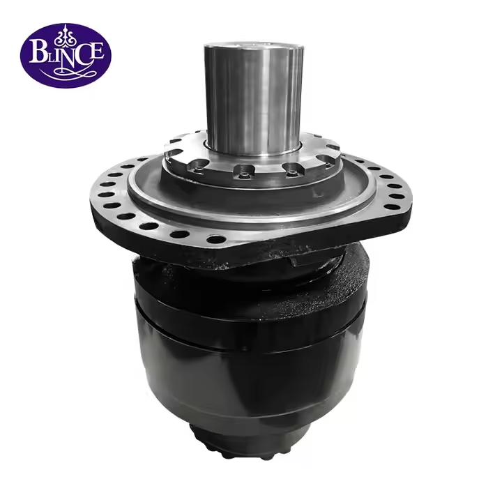
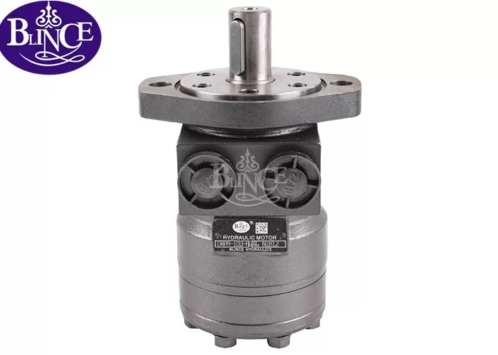
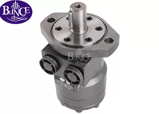
Hydraulic motors often incorporate specialized braking mechanisms to ensure safety and control. In industrial machinery, the ability to brake or hold a load is just as important as the ability to drive it. Decision-makers in industrial procurement need to understand how a hydraulic motor achieves braking so they can select the right solution for safe and efficient operation. This article explains the principles of hydraulic motor braking, covering both brake motors (motors with integrated brakes) and hydraulic lock systems, and offers insights into what to look for when procuring such systems.
Why Effective Braking Is Essential for Hydraulic Motors
Hydraulic motors convert fluid power into rotary motion, driving heavy equipment like winches, conveyors, or vehicle wheels. Without a proper braking system, these motors would simply coast to a stop or, worse, continue moving due to inertia or external loads. An effective brake allows the motor to slow or stop on command, hold a load in place, and provide emergency stopping capability. In fact, a hydraulic motor’s braking mechanism is fundamentally a safety device – it ensures the machine can decelerate and stop reliably, and even holds it safely in position if power is lost. This is crucial for preventing accidents and equipment damage. For example, on an aerial lift or excavator, a failed hydraulic supply without a brake could lead to a dangerous free-wheeling of the motor. Thus, incorporating a dependable brake system in a hydraulic motor is critical for safe, stable operation.
Beyond safety, braking systems improve productivity and control. They allow precise stopping at desired positions (important in industrial processes) and enable emergency stops when needed. A well-designed brake also prevents excessive wear by controlling deceleration rates. For procurement professionals, understanding these benefits helps in choosing hydraulic motors that meet both safety standards and operational requirements – ensuring machinery can be quickly stopped and securely held whenever necessary.

Methods of Hydraulic Motor Braking
Hydraulic motors achieve braking primarily through two means: by hydraulically locking the motor’s fluid circuit or by using a mechanical brake integrated with the motor. Often, modern hydraulic motor brake systems combine both approaches for maximum effectiveness. Below, we break down how each method works:
1. Hydraulic Locking via Valve Control (Fluid Circuit Braking)
One way to brake a hydraulic motor is by manipulating its hydraulic circuit to lock the fluid flow, effectively immobilizing the motor. In practice, this can be done by using control valves (such as a closed-center directional valve) to cut off or block the flow of hydraulic oil to and from the motor. When the supply and return lines are closed, the oil in the motor’s chambers becomes trapped. Because hydraulic oil is nearly incompressible, the trapped fluid resists movement, locking the motor shaft in place – this is often termed a hydraulic lock. In essence, the motor is forced to stop because the fluid can no longer circulate through it.
This hydraulic locking method is commonly employed in closed-loop hydrostatic transmissions and other systems where you can rapidly stop the motor by zeroing pump flow or centering a valve. It provides a straightforward way to hold a load: once the oil flow is cut off, the motor cannot continue to turn under load because any attempt to move is opposed by the locked fluid. For example, if a winch driven by a hydraulic motor needs to hold a heavy load, a hydraulic lock valve (a type of pilot-operated check valve) can be engaged to trap oil in the motor, preventing unwinding of the winch drum.
However, simply locking the fluid can cause stress if done abruptly. When a motor is spinning and suddenly the fluid path is closed, the motor’s inertia makes it act as a pump against a dead end. This can lead to a sharp pressure spike on the high-pressure side and a vacuum on the low-pressure side. To prevent damage from these pressure surges, brake valve components are added to the circuit. A typical brake valve includes a relief valve that will crack open at a set pressure to dissipate excessive pressure safely into a reservoir or accumulator. By bleeding off the excess oil in a controlled way, the relief valve cushions the stop, avoiding a violent shock. At the same time, a check valve or a small feed from an accumulator will add oil to the low-pressure side of the motor, preventing cavitation (which could occur if the motor tries to pull a vacuum). In summary, the hydraulic lock method, when combined with a proper brake valve assembly, can bring a motor to a rapid stop while controlling shock and preventing fluid cavitation.
From a buyer’s perspective, if you opt for a hydraulic motor braking approach that relies on fluid locking, ensure that the system includes these protective valves (sometimes sold as “hydraulic motor brake valves” or counterbalance valves). This will guarantee smooth and safe braking without damaging pressure spikes. Such a system essentially uses the hydraulic circuit itself as the brake — a simple concept with robust results when properly engineered.

2. Integrated Mechanical Brakes (Brake Motors with Spring-Applied Brakes)
The second primary braking method is to use a mechanical brake built into the motor, commonly referred to as a brake motor. These are hydraulic motors that come equipped with an internal friction braking mechanism, usually a spring-applied, hydraulically-released brake. The design typically involves a set of friction discs or a drum connected to the motor’s shaft and a powerful spring that pushes these discs together to lock the shaft when the motor is not active. When hydraulic pressure is supplied to the brake (often via a small hydraulic piston or actuator in the motor), it overcomes the spring force and releases the brake, allowing the motor to turn freely. When pressure is removed (or if there’s a loss of hydraulic pressure), the spring engages again, clamping the brake and locking the motor shaft. This fail-safe design means the brake defaults to the “on” (engaged) position for maximum safety.
Brake motors with spring-applied brakes are extremely valuable in applications where safety and load holding are paramount. For instance, in a hydraulic lift or a mobile crane, if the power is cut or a hose fails, the internal spring brake will automatically activate and prevent a dangerous free-fall. This type of brake is widely used in the automotive and heavy equipment industries for parking and emergency brakes – whenever you see specifications mentioning a “spring brake” or “failsafe brake” on a hydraulic motor, it refers to this mechanism. The key advantage is that no external action is needed to engage the brake; it will engage by default whenever hydraulic pressure is absent, greatly improving safety and convenience for operators.
To give more context, here are the common types of integrated brake mechanisms in hydraulic motors:
Spring-Applied, Hydraulic-Release Brakes: This is the most common design for hydraulic brake motors. A strong spring keeps the brake engaged (motor locked) until hydraulic pressure is fed to release it. It provides fail-safe braking – ensuring the motor stays locked if hydraulic power is lost. These brakes have high holding torque and are ideal for heavy industrial machinery, providing robust holding capacity and automatic safety engagement.
Externally Actuated Brakes (Electric/Pneumatic): In some cases, the brake on a hydraulic motor may be released by an external power source like an electric solenoid or a pneumatic line, instead of hydraulic pressure. Functionally, these can also be spring-engaged, but they use electric or air pressure to disengage. Such setups might be chosen for lighter-duty systems or where an existing electric/pneumatic control scheme is in place. They offer precise control and simplicity in certain applications, though they rely on external power to both engage or disengage the brake. This means if that external power fails, the spring will still engage (providing safety), but coordinating the control is a bit different from purely hydraulic brakes.
When evaluating hydraulic motors with integrated brakes, buyers should consider the brake’s torque rating, response time, and how it interfaces with the hydraulic system. A motor advertised as a “hydraulic brake motor” usually has the brake unit enclosed on one end of the motor. Make sure this brake’s holding torque exceeds the maximum load torque in your application for reliable performance. Additionally, check whether the brake is designed for dynamic stopping (bringing a moving load to a stop) or primarily for holding a static load (parking brake), as this affects the brake material and life. Quality brake motors will specify both dynamic braking capability and static holding capacity.

Ensuring Smooth and Safe Braking Performance
Regardless of method—fluid locking or mechanical brake—there are important considerations to ensure the braking system performs smoothly and safely over the long term:
Controlled Braking to Prevent Shock: As mentioned, hydraulic braking should be designed to avoid sudden jolts. If using valve-based circuit braking, ensure the system includes a brake relief valve and a make-up (anti-cavitation) valve. These components will automatically control abnormal high pressure or vacuum in the lines during braking, resulting in a fast yet shock-free stop. If the motor has an internal brake, the hydraulic supply that releases or applies it should likewise be modulated to avoid slamming the brake on or off. Many systems use orifice restrictions or proportional valves to engage brakes more gradually when needed, especially for very high-speed motors.
Brake Capacity and Sizing: Always verify that the brake (whether internal or an external lock valve) can handle the torque and energy of your application. For a mechanical brake, this means checking the brake’s torque rating and duty cycle. For a hydraulic lock or valve, ensure the valves are sized for the flow and pressure so they can react fast enough and handle the peak pressures generated during stopping. Oversizing a brake a little for safety is generally wise – it should comfortably hold the maximum load plus a safety factor.
Integration with the Hydraulic System: A hydraulic motor brake does not work in isolation; it must integrate with the overall hydraulic circuit. For example, if you have a closed-loop drive motor, you might integrate a shuttle valve and relief valves as a cross-port brake valve kit. If you use a spring-applied motor brake, you’ll need a dedicated line (often via a small control valve or the main directional valve with a brake release port) to release that brake. Hydraulic locks (pilot-operated check valves) can be mounted on the motor ports to lock it when the control valve is centered – these need pilot pressure from the motor’s feed line to release them when you want to move the motor. Ensuring all these parts work together is key to a reliable system. It’s wise to source brake motors and valve assemblies from reputable suppliers who provide detailed circuit diagrams and support.
Maintenance and Reliability: Over time, brake components can wear – brake pads/discs glaze or wear down, springs can fatigue, and valves can get clogged. Choose designs that are robust and easy to maintain. Many brake motors allow for external adjustment or wear compensation, and brake linings can be replaced during service. In your maintenance schedule, include periodic checks of brake function: verify that a de-energized brake indeed holds the load without drift (to catch any hydraulic leaks or wear issues early). For hydraulic lock valves, check for internal leakage that might reduce holding ability. Procuring equipment with good documentation and support will help maintenance teams keep the braking system in top shape, which in turn protects both personnel and the machine.

Conclusion
Hydraulic motor braking systems are vital for the safe and efficient operation of industrial equipment. We’ve seen that there are two primary ways a hydraulic motor achieves braking: by locking the hydraulic fluid flow (using valves to create a hydraulic lock), and by engaging a mechanical brake mechanism built into or attached to the motor (the brake motor approach). Often, the most reliable setups employ both — for example, a spring-applied internal brake provides fail-safe holding, while a well-tuned hydraulic circuit with relief valves ensures smooth deceleration. By understanding how these systems work, industrial procurement professionals can make informed decisions when selecting equipment.
When evaluating hydraulic motors for purchase, consider the braking requirements of your application: Do you need the motor to hold a heavy load indefinitely (if so, an integrated spring brake or a hydraulic lock valve is a must)? Is controlled deceleration critical to prevent damage (ensure the system has the proper brake valves or a variable braking control)? Also pay attention to the term “brake motor” in product specifications – this usually indicates the motor comes with an integrated brake for convenience. Don’t hesitate to ask suppliers about hydraulic lock valves, brake torque ratings, and safety features; reputable manufacturers will provide these details to ensure their motors meet your needs.
In summary, a hydraulic motor with a well-designed braking system (whether through fluid locking or an internal brake, or both) will enhance your machine’s safety, compliance, and performance. It gives operators confidence to control heavy loads and provides protection in emergency scenarios. By selecting the right hydraulic motor brake solution and maintaining it, you ensure your industrial equipment operates with both power and precision – driving productivity while keeping people and assets safe.


