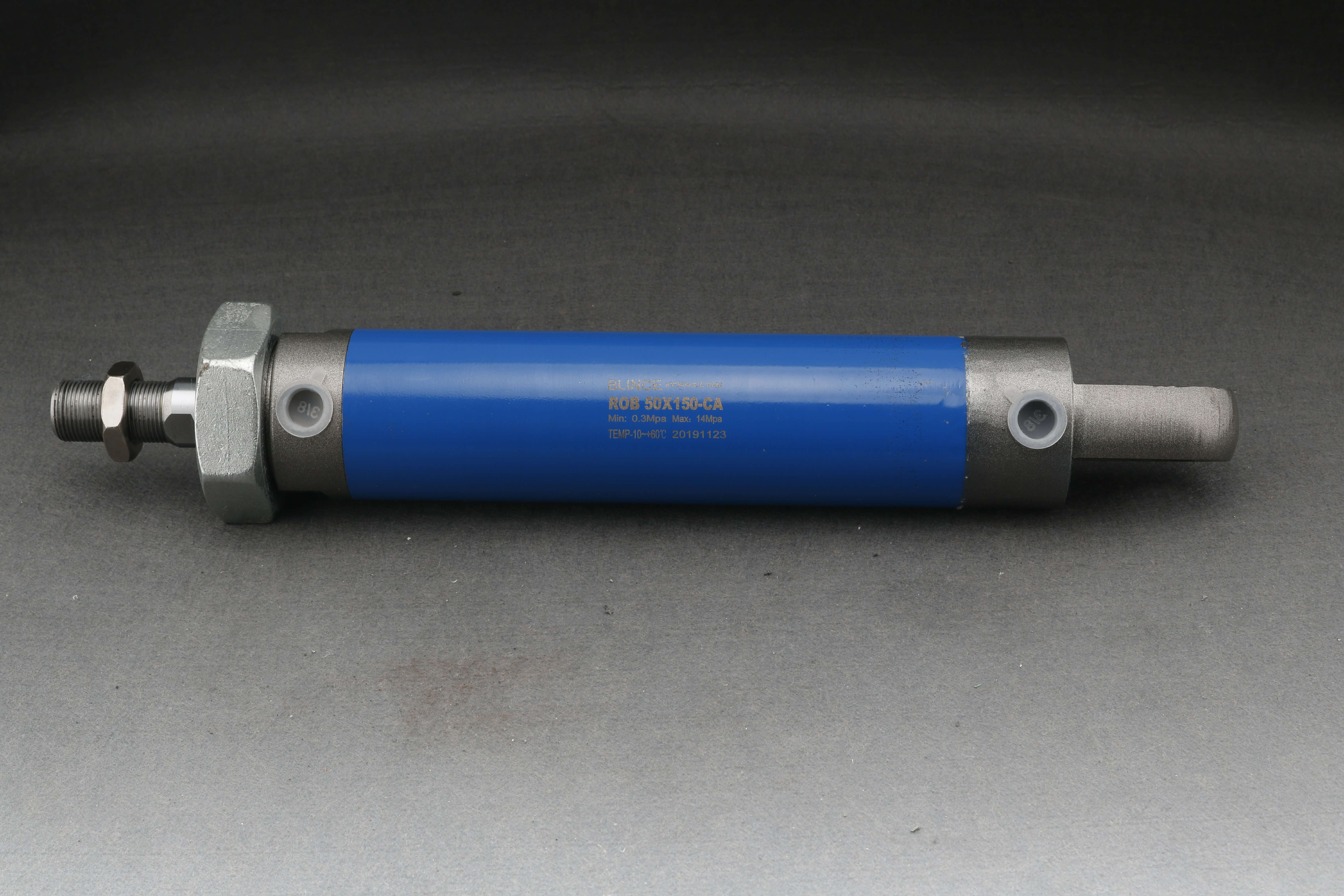
In fluid power engineering, precision dictates performance. Estimating cylinder capabilities based on nominal system pressure rather than exact mathematical modeling leads to mechanical failures, safety hazards, or unnecessary capital expenditure. Miscalculating force requirements results in undersized cylinders that stall under load. Conversely, oversized cylinders demand larger pumps, heavier mounting structures, and excessive fluid volumes, inflating system footprints. An undersized cylinder fails to move the required mass, causing fluid to bypass through relief valves and generating excessive heat. Specifying a cylinder with too large of a bore wastes physical space and requires higher flow rates to hit target cycle times. This guide provides the exact mathematical frameworks for hydraulic cylinderforce calculation. We detail how to account for real-world mechanical inefficiencies and offer a technical evaluation framework for specifying the correct cylinder for your operational requirements.
Key Takeaways
Theoretical vs. Actual Yield: The fundamental formula (Force = Pressure × Area) provides a theoretical baseline; actual output is typically 5% to 10% lower due to seal friction and internal pressure drops.
Directional Variance: Retraction (pull) force is inherently lower than extension (push) force in standard double-acting cylinders due to the volume occupied by the piston rod.
Single vs. Double-Acting Dynamics: Single-acting cylinders must account for spring-return resistance, which deducts from the total theoretical push force.
System Trade-offs: Achieving a specific force target requires balancing bore size against system pressure—larger bores operate at lower pressures but require more physical space and fluid volume.
Risk Mitigation: Force calculations must be paired with stroke length and mounting style evaluations to prevent catastrophic rod buckling under heavy loads.
Table of Contents
Toggle
The Fundamental Physics of Hydraulic Cylinder Force
To specify a fluid power system accurately, you must understand the physical principles governing fluid behavior under confinement. Hydraulic systems operate on the principle of fluid incompressibility. This characteristic allows them to transmit immense power across flexible distances without significant energy loss.
Pascal’s Law for Hydraulic Cylinders
The foundation of all fluid power calculations rests on Pascal's Law. This principle states that pressure applied to a confined, incompressible fluid transmits equally and undiminished in all directions throughout the fluid. When a hydraulic pump forces oil into a cylinder barrel, the fluid pressurizes. This pressurized fluid exerts equal force against the cylinder walls, the end caps, and the face of the piston. Because the cylinder barrel and caps are rigidly fixed, the fluid's pressure forces the movable piston to travel linearly down the barrel. This action converts fluid power directly into mechanical motion.
Key Variables for Force Calculation
Before executing any mathematical formulas, establish the core variables involved in the calculation. Mixing units or misunderstanding these foundational metrics will result in severe sizing errors on the shop floor.
F (Force): The total mechanical output generated by the cylinder. This represents the actual pushing or pulling power available to move a load. In Imperial systems, force is measured in pounds-force (lbf) or US Tons for heavy industrial applications. In Metric systems, we measure it in Newtons (N) or kiloNewtons (kN).
P (Pressure): The system operating pressure at the cylinder port. This is the energy potential of the fluid. You must use the pressure available at the port, not just the maximum rating of the hydraulic pump. Pressure is typically measured in Pounds per Square Inch (PSI) or Bar.
A (Effective Area): The surface area of the piston exposed to the pressurized fluid. This is the physical space where the fluid pressure acts to generate motion. Effective area is measured in square inches (in⊃2;) or square millimeters (mm²).
The Baseline Equation
The relationship between these three variables is expressed in the core fluid power formula: F = P × A. Force equals Pressure multiplied by Area. This equation dictates that you can increase the mechanical output of a cylinder by either increasing the system pressure or increasing the surface area of the piston. Every subsequent calculation builds upon this fundamental mathematical relationship.
Step-by-Step Hydraulic Cylinder Force Calculation
Applying the baseline equation to real-world hardware requires specific geometric calculations. Cylinders operate in two directions—extension and retraction. The available surface area changes depending on the direction of travel.
Calculating Extension Force (Push)
During the extension stroke, hydraulic fluid enters the cap end (blind end) of the cylinder. The fluid presses against the entire circular surface area of the piston. To find this area, calculate the area of a circle based on the cylinder's internal bore diameter.
The formula for the full bore area is: Area = π × r⊃2; (where r is the radius, or half the diameter). Alternatively, use Area = π × (Diameter/2)⊃2;. For example, a cylinder with a 4-inch bore has a radius of 2 inches. Squaring the radius gives 4. Multiplying by Pi (3.14159) yields a full bore area of 12.56 square inches.
Once you have the full piston surface area, apply it to the F = P × A equation. If your system operates at 2,500 PSI, multiply 2,500 by 12.56 to determine a theoretical extension force of 31,400 lbf.
Calculating Retraction Force (Pull) in Double-Acting Cylinders
Double-acting cylinders use hydraulic pressure to both extend and retract. During the retraction stroke, fluid enters the rod end of the cylinder. The physical presence of the piston rod occupies space, reducing the amount of piston surface area available for the pressurized fluid to act upon. We call this reduced area the annular area.
To calculate the annular area, first determine the cross-sectional area of the rod using the same circular area formula: Rod Area = π × (Rod Diameter/2)⊃2;. Next, subtract this rod area from the full bore area calculated previously. The resulting formula is: Effective Area = Full Bore Area - Rod Area.
Because the effective area is always smaller during retraction, standard double-acting cylinders naturally possess a force differential. The pull stroke always generates less force than the push stroke at the exact same system pressure. Engineers account for this differential when designing applications that require heavy pulling, such as presses or lifting mechanisms.
Accounting for Single-Acting Cylinders
Single-acting cylinders use hydraulic pressure to extend the rod but rely on an internal mechanical spring or external load gravity to retract it. When calculating the extension force for a spring-return cylinder, the spring itself presents mechanical resistance that fights against the hydraulic fluid.
To determine the actual usable output, subtract the spring's resistance force from the gross theoretical force. The formula becomes: Net Force = (P × A) - Spring Resistance. Spring resistance varies depending on how far the spring is compressed. This means the available hydraulic cylinderforce actually decreases slightly as the cylinder reaches the end of its extension stroke.
Unit Conversions and Standardization
Fluid power components are manufactured globally. Engineers frequently navigate between Imperial and Metric units. Failing to convert units correctly invalidates calculations and leads to field failures. Below is a standardized conversion table to ensure calculation accuracy.
Measurement
Imperial Unit
Metric Unit
Conversion Formula
Pressure
PSI (Pounds per Sq. Inch)
Bar
1 Bar = 14.5038 PSI
Area / Diameter
Inches (in)
Millimeters (mm)
1 Inch = 25.4 mm
Force
Pounds-force (lbf)
Newtons (N)
1 lbf = 4.44822 N
Heavy Force
Pounds-force (lbf)
US Tons
US Tons = lbf / 2,000
For press and heavy-lifting specifications, calculating output in US Tons is the industry standard. Once you determine the total pounds-force (lbf), divide that figure by 2,000 to find the precise tonnage.
To speed up field calculations, refer to this standard NFPA bore size reference table. It outlines the theoretical push area for common industrial cylinder sizes.
Bore Diameter (Inches)
Radius (Inches)
Push Area (Square Inches)
Force at 3,000 PSI (lbf)
1.50
0.75
1.76
5,280
2.00
1.00
3.14
9,420
2.50
1.25
4.91
14,730
3.25
1.625
8.30
24,900
4.00
2.00
12.56
37,680
5.00
2.50
19.63
58,890
Real-World Factors: Theoretical vs Actual Output Force
The F = P × A formula provides a theoretical baseline. However, hydraulic systems do not operate in a vacuum. Real-world mechanical and fluid dynamic inefficiencies guarantee that the actual force delivered to the load will always be lower than the mathematical theory suggests.
Static (Breakaway) vs. Dynamic (Running) Friction
Every hydraulic cylinder relies on internal seals to prevent fluid from bypassing the piston and leaking out of the rod gland. These seals, often made from polyurethane, PTFE, or nitrile rubber, create physical friction against the honed steel barrel and the chrome-plated rod. This friction directly counteracts the hydraulic force.
Friction is not constant. Static friction, or breakaway friction, is the resistance encountered when initiating movement from a dead stop. Breakaway friction is significantly higher than dynamic running friction, which occurs once the cylinder is already in motion. To ensure safe specification, apply an industry-standard deduction to your theoretical calculations. Expect a 5% to 10% loss of total force due to seal friction, depending on the tightness of the seal tolerances and the viscosity of the hydraulic fluid.
System Pressure Drops (ΔP)
Theoretical calculations often mistakenly use the hydraulic pump's maximum rated pressure as the "P" variable. In reality, fluid loses energy as it travels through the system. As hydraulic oil moves through hoses, navigates 90-degree fittings, and passes through the restrictive orifices of directional control valves, it experiences pressure drops.
By the time the fluid reaches the actual cylinder port, the operating pressure may be several hundred PSI lower than the pump output. Accurate force calculations require installing a pressure gauge directly at the cylinder port during operation to determine the true available pressure, rather than relying on the pump's data plate.
Back Pressure Considerations
In a double-acting cylinder, fluid must exit the non-pressurized side of the cylinder as the piston moves. During extension, fluid in the rod end must be forced out of the port, through the return lines, and back into the reservoir. The restrictive nature of the return plumbing creates back pressure.
This back pressure pushes against the non-pressurized side of the piston, creating a marginal resistance that deducts from the net force output. Back pressure becomes a significant limiting factor in systems with undersized return lines or heavily restrictive proportional valves.
Practical Calculation Examples
Applying the theory to practical scenarios clarifies the sizing process. The following examples demonstrate how to navigate real-world constraints when specifying fluid power equipment.
Example 1: Sizing a Cylinder for a Heavy Lifting Application (Push)
Scenario: You are designing a lifting mechanism that must push a 15,000 lb load vertically. The hydraulic power unit delivers a reliable 3,000 PSI at the cylinder port. You need to determine the minimum bore size required.
Establish the required effective area using a variation of the core formula: Area = Force / Pressure.
Divide the 15,000 lb load by the 3,000 PSI system pressure. This yields a theoretical required area of 5.0 square inches.
Factor in a 10% safety margin to account for seal friction and mechanical binding. Increase the required area to 5.5 square inches.
Find the required bore diameter using the formula: Diameter = √((Area / π) × 4).
Calculate √((5.5 / 3.14159) × 4) to get a minimum required bore diameter of approximately 2.64 inches.
Since cylinders are manufactured in standard sizes, round up and specify a standard 3.25-inch NFPA bore cylinder for this application.
Example 2: Specifying a Double-Acting Cylinder for a Press (Pull/Retract & Tonnage)
Scenario: You are designing a pulling application for a press that requires exactly 11,780 lbf of retraction force. Due to physical space constraints, you are limited to a maximum bore size of 4 inches. The application requires a heavy-duty 2-inch rod to prevent bending. You need to calculate the required system pressure and determine the precise tonnage.
Calculate the full bore area of the 4-inch cylinder. The radius is 2 inches. Area = π × 2⊃2;, which equals 12.56 square inches.
Calculate the rod area. The 2-inch rod has a radius of 1 inch. Area = π × 1⊃2;, which equals 3.14 square inches.
Subtract the rod area from the bore area to find the annular effective area: 12.56 - 3.14 = 9.42 square inches.
Determine the required pressure using Pressure = Force / Area. Divide the required 11,780 lbf by the 9.42 square inch effective area. The system must deliver exactly 1,250.5 PSI to the rod-end port to achieve the desired pull force.
Convert the final output into precision tonnage by dividing the 11,780 lbf by 2,000. The press will operate at approximately 5.89 US Tons of pulling force.
Example 3: Mobile Equipment Boom Cylinder (High Pressure)
Scenario: An excavator boom requires a massive push force to break through compacted soil. The system operates at a high pressure of 4,500 PSI. The cylinder has a 5-inch bore. You need to find the theoretical push force.
Find the radius of the 5-inch bore, which is 2.5 inches.
Calculate the area: 3.14159 × (2.5)⊃2; = 19.63 square inches.
Multiply the area by the pressure: 19.63 × 4,500 = 88,335 lbf.
Apply a 5% friction deduction for high-efficiency seals: 88,335 × 0.95 = 83,918 lbf of actual working force.
Engineering Evaluation: Translating Calculations into Cylinder Selection
Performing the mathematical calculations is only the first phase of system design. Translating those numbers into a physical hardware specification requires evaluating system trade-offs, structural limitations, and manufacturing constraints.
Manual Formulas vs. Digital Calculators
Digital fluid power calculators provided by major manufacturers offer rapid prototyping capabilities. They allow engineers to input variables and instantly generate baseline sizing metrics. These tools work well for initial feasibility studies.
However, digital calculators assume ideal conditions. They cannot account for the specific plumbing layout, valve restrictions, or unique friction coefficients of your proprietary machine design. Verify digital tool outputs with manual engineering calculations to ensure all unique system inefficiencies are properly documented and accommodated.
Bore Size vs. Operating Pressure Trade-offs
When you need to achieve a specific force target, you face a distinct engineering decision matrix: do you increase the system pressure, or do you increase the cylinder bore size?
Increasing system pressure allows you to use a smaller, lighter cylinder. This saves valuable physical space in compact machine designs. High-pressure systems require heavier-duty hoses, robust pumps, and specialized valves, which increases the overall system cost and complexity.
Lowering the system pressure requires specifying a larger bore cylinder to hit the same force target. While lower pressure components are generally less expensive and experience less wear, a larger cylinder demands a greater volume of hydraulic fluid. This requires a larger reservoir and a higher-flow pump to maintain acceptable cycle times.
Rod Buckling and Stroke Length Limitations
Calculating sufficient force is only step one. When a cylinder extends to push a heavy load, the piston rod acts as a slender column under compression. Long-stroke cylinders pushing massive weights are highly susceptible to catastrophic bending, known as rod buckling.
To prevent the rod from folding under pressure, execute a secondary calculation using Euler's column formula. This formula evaluates the rod's material elasticity, its moment of inertia, the unsupported stroke length, and the specific mounting style. If the buckling calculation indicates a failure risk, specify a cylinder with a larger rod diameter, even if the hydraulic force calculations suggest a smaller rod would suffice.
Standard Off-the-Shelf vs. Custom Engineered Cylinders
Once the technical specifications are locked, decide between standard and custom hardware. Standard tie-rod or welded cylinders are manufactured in common bore and rod combinations. They are cost-effective, readily available, and easy to source replacement seal kits for. If your calculations align with standard dimensions, standard units are the optimal choice.
If your application demands highly specific force-to-footprint ratios, extreme operating pressures, or unique mounting configurations that standard catalogs cannot accommodate, invest in custom-machined cylinders. Custom engineering ensures the exact calculated effective area is achieved without compromising machine geometry.
Installation Risks and Preventive Solutions
Even perfectly calculated cylinders fail prematurely if implemented poorly. Real-world operational hazards introduce stresses that mathematical formulas do not inherently account for.
Side Loading
Hydraulic cylinders generate force strictly in a linear direction along the axis of the piston rod. Applying force at an angle, or allowing the load to shift laterally during the stroke, creates side loading. This uneven pressure forces the rod against one side of the gland, causing rapid, uneven seal wear, scored cylinder tubes, and eventual fluid bypass.
To mitigate side loading, specify appropriate mounting styles that allow for slight articulation. Integrating spherical bearings, trunnion mounts, or clevis brackets allows the cylinder to pivot slightly. This absorbs lateral movement and ensures the force remains perfectly linear throughout the entire stroke. For long horizontal strokes, consider adding internal stop tubes to increase the bearing surface area between the piston and the gland.
Shock Loads and Pressure Spikes
Calculations typically assume static or smoothly accelerating loads. In reality, industrial applications frequently encounter dynamic shock loads. Dropping a heavy weight onto a supporting cylinder, or hitting a mechanical hard stop at high speed, causes instantaneous pressure spikes inside the barrel.
These dynamic spikes easily exceed the calculated static pressure by a factor of three or four, instantly blowing out seals or bursting the steel barrel. To protect the system, integrate cross-port relief valves close to the cylinder ports to vent excess pressure instantly. Cylinders operating in high-shock environments must be specified with higher yield strength materials and aggressive safety factors, demanding 3:1 or 4:1 burst ratings relative to the nominal operating pressure.
Conclusion
Measure the actual operating pressure directly at the cylinder port using a calibrated gauge to account for upstream pressure drops.
Calculate the required effective area based on your peak load, then add a 10% safety margin to compensate for seal friction and mechanical binding.
Run Euler's column formula on your selected rod diameter and stroke length to verify the cylinder will not buckle under maximum extension.
Consult with a fluid power manufacturer to finalize the seal package and mounting style based on your specific environmental conditions.
FAQ
Q: How do you calculate hydraulic cylinder force?
A: You calculate force using the fundamental formula: Force = Pressure × Area (F = P × A). Multiply the system operating pressure (in PSI or Bar) by the effective surface area of the piston (in square inches or square millimeters) exposed to the pressurized fluid.
Q: Why is retraction force less than extension force in a double-acting hydraulic cylinder?
A: Retraction force is lower because the physical presence of the piston rod occupies space inside the cylinder barrel. This reduces the total surface area available for the pressurized fluid to push against during the pull stroke, resulting in less overall force.
Q: What is the formula for effective area in a hydraulic cylinder?
A: For the extension (push) stroke, the effective area formula is Area = π × r⊃2;. For the retraction (pull) stroke, you must subtract the rod's area. The formula becomes: Area = (π × r⊃2; of the cylinder bore) - (π × r⊃2; of the piston rod).
Q: How do I convert hydraulic cylinder force to tons?
A: Once you have calculated the total force output in pounds-force (lbf), you divide that number by 2,000. This converts the measurement into US Tons, which is the standard metric used for specifying press applications and heavy lifting equipment.
Q: How much force is lost to friction in a hydraulic system?
A: As a standard engineering rule of thumb, expect a 5% to 10% loss of theoretical force due to internal friction. This loss varies depending on the specific seal material type, fluid viscosity, and the precision of the cylinder alignment.
Q: How do I choose the right bore size for my required force?
A: Divide your required force by your available system pressure to find the target effective area. Once you have the target area, use the formula Diameter = √((Area / π) × 4) to calculate the required bore diameter, then round up to the nearest standard size.
Q: Can I increase hydraulic cylinder force without changing the cylinder?
A: Yes, force can only be increased without changing the cylinder by raising the system operating pressure at the pump. However, you must first verify that the cylinder barrel, rod, seals, and connecting hoses are safely rated to handle the higher PSI.