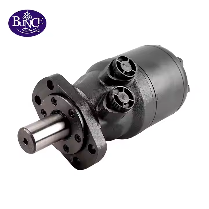
OMH displacement and continuous duty selection
OMH motors use shaft flow distribution with a roller-type rotor and stator arrangement. Each displacement has a different operating envelope; the family table is useful when a buyer needs to balance continuous torque, speed and hydraulic supply.
OMH model data
| Model | Displacement cm3/rev | Continuous pressure differential MPa | Continuous torque N m | Maximum continuous speed rpm |
| OMH 200 | 203.2 | 17.5 | 510 | 366 |
| OMH 250 | 255.9 | 17.5 | 621 | 290 |
| OMH 315 | 316.1 | 17.5 | 740 | 236 |
| OMH 400 | 406.4 | 15.5 | 850 | 183 |
| OMH 500 | 489.2 | 12.5 | 830 | 155 |
The table lists selected OMH catalogue configurations. Check the required shaft version and drain arrangement. The model code is not an exact geometric displacement value.
Comparing OMH 200 and OMH 500
OMH 200 lists 203.2 cm3/rev, 17.5 MPa continuous pressure differential, 510 Nm continuous torque and 366 rpm maximum continuous speed. OMH 500 lists 489.2 cm3/rev, 12.5 MPa, 830 Nm and 155 rpm. The comparison shows why displacement, pressure and speed must be read together.
Compare the required torque at the intended running speed with the selected model data. A larger displacement changes the flow needed for a target speed; it does not establish a proportional increase in continuous torque. The selected shaft version and the operating point still determine which catalogue data apply.
Flow and speed for OMH 200
As a calculated example, assume 30 L/min reaches the OMH 200 with 203.2 cm3/rev displacement. Ideal motor speed is flow x 1000 / displacement, giving 30 x 1000 / 203.2 = approximately 147.6 rpm before volumetric losses. This is a flow estimate, not a measured BLINCE performance point or confirmation that the motor can deliver rated torque at that speed.
Actual speed and available torque depend on the operating point, oil conditions and motor losses. Use the relevant curve, starting data and inlet and outlet conditions to complete the selection. If the machine needs very low speed or changes load rapidly, include that duty explicitly in the enquiry.
OMH installation and ordering information
| Item | Details for the enquiry |
| Shaft | OMH shaft profile diameter key or spline usable length and external loading |
| Mounting | Flange form pilot bolt pattern and available space |
| Oil ports | Connection type position and hose clearance from the approved drawing |
| Return and drain | Outlet pressure and the drain arrangement for the supplied motor |
| Duty point | Required starting torque running torque speed and available flow |
For a conveyor, brush or rotary assembly enquiry, state whether the motor connects directly or through a belt, sprocket or gearbox. Include the load on the output shaft and its position. These are machine-duty examples; the actual configuration must be reviewed for its own hydraulic and mechanical requirements.
OMH purchase questions
What displacement is listed for OMH 200
The reviewed catalogue lists 203.2 cm3/rev for OMH 200. Use the geometric displacement for the matching configuration rather than assuming the model number is an exact displacement.
Can the highest OMH torque and speed be combined
The table entries are limits or model-specific ratings, not a single performance point. Check the intended speed, pressure and load against the applicable operating curve and duty instructions.
Which details identify the OMH replacement configuration
Send the full existing reference and nameplate photograph, the shaft and mounting drawing, port details and the working duty. Include control or brake connections if they are part of the existing assembly.
Request a configuration quotation for OMH
Send BLINCE the complete OMH reference, quantity and installation drawing. Add the required starting torque, running speed, available flow and inlet and outlet pressures, together with the connection details that must be retained.