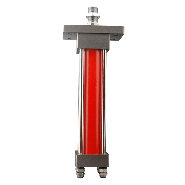
A replacement order needs two endpoint dimensions as well as hydraulic cylinder stroke length. For a conventional single-stage cylinder, stroke is the piston’s specified travel. With fixed attachments, it equals extended mounting length minus retracted mounting length, measured from unchanged references. Two cylinders can each travel 200 mm and still have different closed lengths.
Use the machine’s service procedure before removing, moving or testing the cylinder. Support the loads, isolate power and control stored pressure as that procedure requires. If damage prevents safe movement, send the dimensions that can be established and mark the remaining endpoint unknown.
Define the ends of each length measurement
For the fixed-eye example below, the symbols mean Lr for the closed mounting distance and Le for the open mounting distance. Take them with the attachments unchanged. Subtracting gives working stroke S:
S = Le − Lr
For the proposed replacement, checking S alone omits the position of the whole travel interval. A cylinder could have the required stroke and place both ends of the interval too far from the machine's base pin. The two installed lengths show that difference immediately.
Dimension
What it establishes
What to put beside it
Retracted mounting length, Lr
Where the rod-end mounting reference sits at the specified retracted position
Mounting references, attachment details and measurement source
Working stroke, S
Available linear movement between the specified cylinder positions
Whether the value is measured travel, drawing stroke or a manufacturer code
Extended mounting length, Le
Where the same rod-end reference sits at the specified extended position
The same references and attachments used for Lr
Required machine working positions
Where the mechanism needs to start and finish
Machine drawing or documented operating limits
Watch which positions the measurement describes. Valve or sensor control may reverse the motion before the available travel is exhausted. Label a measurement between those normal positions as used travel, then obtain the available working stroke from the identified drawing or a qualified inspection.
Yates Industries' replacement measurement guide also separates bore, rod diameter, stroke and mounting information. Its advice to retain identification markings is useful when a partly accessible sample cannot provide a complete dimensional record. A legible original code may resolve a dimension more reliably than a measurement taken around a bent guard.
A 200 mm stroke can still put both pins in the wrong place
Take an illustrative two-eye assembly specified at 480 mm between pin centers when retracted and 680 mm when extended. Subtraction gives 200 mm of required cylinder travel. The dimensions in this example were chosen for the comparison; they describe no BLINCE model or field installation.
Two offered candidates illustrate different conflicts:
Example configuration
Retracted pin centers
Working stroke
Extended pin centers
Comparison with the specified endpoints
Required geometry
480 mm
200 mm
680 mm
Drawing reference
Candidate A
495 mm
200 mm
695 mm
Both cylinder endpoints are 15 mm longer
Candidate B
480 mm
210 mm
690 mm
Fits the specified retracted length; has 10 mm of additional extension
At 495 mm retracted, Candidate A starts 15 mm beyond the specified 480 mm position. Its 200 mm stroke carries that offset through to extension. The machine’s original retracted position may therefore be out of reach. Matching the travel distance has left the starting position wrong.
Candidate B starts at the specified 480 mm position and can continue to 690 mm. The machine requirement stops at 680 mm. Before accepting B, resolve how the approved control and stopping arrangement would handle the extra 10 mm. The comparison sheet supplies no approval to drive farther or to let an existing bracket absorb the stop.
An adjustable eye may offer a permitted range for setting mounting length. Check its thread engagement, locking and articulation requirements before using that adjustment. Measure Lr and Le with the eye at the same recorded setting. Moving the eye alters the attachment position, while the piston retains its existing internal travel.
Write “including both fitted eyes” or identify the excluded attachments beside the dimensions. The supplier can then compare the same assembly. A bare-body drawing omits the length added by a separate clevis, bearing or threaded adapter.
Work from the identification and the usable sample
The machine model and cylinder marking give the inquiry a starting identity. Add photographs taken where access is safe: the full assembly, both mounts, the ports and any sensor. Mark the pieces being retained on the machine. This separates the supplied cylinder from attachments that may appear in the picture but are outside the order.
For a safely removed sample, choose intact measuring surfaces. A worn pin needs a note about its condition beside the caliper reading. If its diameter differs along two axes, send both readings. Likewise, photograph one-sided wear in an eye so the supplier can distinguish an intended dimension from the material that remains.
A reading taken with a bent rod has a limited meaning. It describes the position at which that sample can be measured, which may be short of its intended endpoint. Put the damage description beside the length. The workshop or supplier can then decide how to establish the missing endpoint without treating a jammed position as a design dimension.
State the measurement method on the dimensional sketch. Use the scaled photograph to identify the measured features and show damage; perspective can distort their apparent spacing.
Obtain bore from identified documentation or qualified inspection. Measuring across the outside of the barrel includes the wall and leaves its design-dependent thickness unresolved. On the rod, use an undamaged external section for the diameter measurement and label it “rod.” Put the rod-end thread in another field; the two dimensions serve different checks.
Where a repaired bracket or changed eye has altered the sample, keep the original drawing value in the record. Add the measured value and photograph of the alteration beside it. This gives the reviewer the location and size of the discrepancy to investigate.
Change the reference when the mount changes
Use the locating features of the actual mount. For a flange, inspect the dimension from its mounting face to the rod-end connection. For feet, the centerline height and fastening pattern locate the body on its support. With trunnions, the pivot axis has a position along the body that must be carried into the replacement drawing.
Dimension from that flange face or pivot axis on the side view, with the rod axis visible. Keep a separate overall length for the clearance check. A projecting cap, port block or thread can extend beyond the mounting reference without changing how the cylinder is located.
Include the fitted rod eye or clevis in that view. Compare its width and its position along the rod with the proposed attachment. Check the space between lugs, the bearing width and pin retention alongside pin diameter. Together these dimensions show whether the complete connection can assemble and articulate through the intended movement.
For the differences in support and load path, refer to BLINCE’s cylinder mounting guide. Include a proposed mount change in the engineering review, with its selected installed dimensions. Retaining nominal stroke does not retain all the assumptions of the original support arrangement.
On the order drawing, place the mounting code and rod-end attachment beside Lr and Le. A family outline may show several mount options. The quotation needs to identify which of those outlines applies to the supplied part.
Linkage movement can differ from cylinder travel
For a rotating arm, begin with its required angular positions. From those positions, calculate the distance between the cylinder pins. The arm tip follows an arc; the cylinder follows the changing straight-line distance between its mount points. Vertical displacement, arc length and cylinder travel will generally give different values.
The planar example uses the following chosen geometry:
Item
Assumed position or dimension
Fixed cylinder pin
(0, 0) mm
Arm pivot
(300, 0) mm
Moving pin radius about the arm pivot
150 mm
Angle θ
Measured from the positive horizontal axis
The moving pin is at (300 + 150 cos θ, 150 sin θ). Applying the distance formula back to (0, 0) gives mounting length L:
L = √[(300 + 150 cos θ)² + (150 sin θ)²] mm
At 60°, L is approximately 396.86 mm. At 120°, it is approximately 259.81 mm. Movement between those angles requires a change in pin-center distance of approximately 137.06 mm. Over the same angle, the pin moves along an arc of approximately 157.08 mm, calculated as 150 × π/3.
The example is limited to two-dimensional geometry. The 137.06 mm change is the result to compare with cylinder movement, while 157.08 mm describes the pin’s arc. Load capacity remains uncalculated. A real mechanism needs force, support, stability and clearance checks throughout motion, including positions with poor mechanical advantage.
On an existing installation, carry the identified pivot locations into the replacement model. Treat a moved pivot as an engineering change. Run the model through intermediate positions as well: the lengths may agree at both ends while a port block or cylinder body meets another part midway through the swing.
Separate a stop tube from a cushion or position limit
A stop tube changes the cylinder's internal support arrangement. Cylinder manufacturers may use different drawing and ordering conventions to express its effect on working stroke and overall length. Keep the selected manufacturer's definitions attached to the specification.
In the stop-tube section of Parker's Atlas HMI catalog, gross stroke includes the net working stroke plus the stop-tube length. That is a stated convention for the catalog's cylinder system. A BLINCE order needs its own drawing to identify working travel, stop-tube provision and installed dimensions; the Parker code cannot be transferred to it.
When a quote includes a stop tube, have the supplier mark the delivered working travel and both installed lengths on the selected drawing. That lets the buyer compare the complete cylinder with the machine. A catalog maximum and an assumed spacer length leave too much of this assembly undefined.
Keep separate entries for the cushion, sensor and any stroke adjustment. One controls end-of-travel deceleration, another provides position information, and the adjustment sets travel as its design permits. Their functions and supplied parts need to be identifiable on the quotation, alongside the stop-tube detail.
Include the setting with an identified adjustable stop. The same hardware can give different available travel at another setting, so a photograph of the component alone may leave the endpoint uncertain. An unrecognized adjustable feature needs comparison with the assembly drawing before its setting is changed.
Review stroke reserve against the actual stopping arrangement
Put the required operating positions on the machine drawing and check their stopping limits against the selected design. Before adopting an 80% recommendation, establish what problem that reserve is intended to address. Document the control arrangement that keeps the mechanism within the specified positions.
Distinguish a cylinder reaching its designed end position under an approved duty from a moving load striking an unreviewed stop. The review needs the moving mass, speed, orientation and way the energy is absorbed. Reserving some unused travel does not establish that the control system will slow the load or keep it within the intended operating positions.
The explanation of cushioning in Parker’s industrial cylinder literature starts from kinetic energy and deceleration. For selection, specify the stopping duty and review the energy and forces with the cushion and circuit being used. Partial-stroke operation still needs a defined way to slow and stop the load.
For an illustrative effective mass of 200 kg moving horizontally, use E = ½mv²:
Chosen speed v
Calculated kinetic energy E
0.2 m/s
½ × 200 × 0.2² = 4 J
0.4 m/s
½ × 200 × 0.4² = 16 J
Doubling speed gives four times the kinetic energy. This calculation excludes friction and other energy inputs. It contains no BLINCE cushion capacity, so the result remains an energy comparison rather than approval of a stopping duty.
Describe what slows and stops the original motion. It may depend on valve control, an internal cushion, an external stop or a sensor in the control sequence. Carry those details into the replacement specification. A quote for the correct stroke still needs to answer which stopping features are supplied.
Long travel needs a support and compression review
A rod under a pushing load needs a stability check at the relevant extended position. Stroke helps establish that position. Add rod size, force, mounting and guidance to complete the review inputs, including any extension beyond the standard rod end. A family’s maximum stroke describes an offering rather than the load support of this assembly.
In Bosch Rexroth’s buckling calculation notes, installation angle enters the calculation and the diagrams distinguish guided from unguided loads. The notes show installation lengths and rod extensions separately. Use that distinction when preparing the support view for a proposed long-stroke replacement.
On the support drawing, mark the critical push or pull direction, cylinder orientation and any extra rod-end extension. Include the relevant pressure and load conditions with that view. The engineer can then review the extended assembly that will be supplied.
Compare a proposed larger rod as a new configuration. Its rod-side effective area will differ, and its attachment may differ too. Include those changes in the hydraulic and support review. A diameter increase by itself leaves the causes of misalignment or excessive reach unresolved.
Inspect the machine’s guides and mounts when uneven wear or a bent rod prompted the replacement. New cylinder parts leave wear in that structure in place. A pivot bearing offers its designed articulation, with limits that still have to suit the load direction and lateral forces.
Keep the body, ports and hoses inside the movement envelope
Model the cylinder as the complete supplied assembly, including a valve block or trunnion support if fitted. Inspect its approach to surrounding parts during movement. Record the position where clearance is smallest. An endpoint view can miss a contact that occurs while the body swings.
On the port sketch, write which end faces the viewer. A left-side connection viewed from the rod becomes a right-side connection viewed from the base. Draw the fitted connector projecting from the port to locate the actual hose departure point.
Trace each hose while the mechanism moves. Relocating a port farther from a pivot can change the hose path even when its thread stays the same. Check for tension and restricted movement using the hose and machine requirements. Accepting a relocated port includes accepting a route that can accommodate it.
Show the pin’s insertion direction and retention on the installation sketch. A nearby frame member might clear the fitted pin yet obstruct its insertion or the tool needed to retain it. Check that assembly route and the later removal sequence before agreeing to a revised end arrangement.
What the BLINCE product pages help you shortlist
The BLINCE hydraulic cylinder category is the commercial starting point for a replacement inquiry. It contains several constructions and product families. Select the route from the machine's actual cylinder and mounting requirements, then compare the proposed configuration drawing with the old assembly.
For the HOB double-acting tie-rod family, BLINCE’s public page gives 0.3–14 MPa pressure, 40–250 mm bores and a maximum stated stroke of 5,000 mm. Treat these as family-level entries. To order a particular stroke, obtain the rating and drawing for its selected bore, rod and mount under the proposed duty.
The MOB 7 MPa cylinder page describes a light-type family and mentions double-rod and adjustable-stroke variants. An available option name is a starting point for inquiry. The ordered version needs the actual dimensions and operating limits; a standard single-rod outline does not define every optional arrangement.
If considering a change between these families, use BLINCE's HOB and MOB comparison alongside the selected drawings. A higher family pressure figure does not settle mounting length, rod-end thread or the required pull duty. Keep any proposed family change visible on the quotation.
Distinguish a replacement from a change in machine design
For a direct replacement, begin with the identified original configuration and add the machine’s documented modifications. The sample shows what is installed now; the equipment list may describe an earlier version. Establish which version the replacement is required to reproduce.
Put proposed extra travel, a moved pivot or a new attachment on a separate change sketch. Trace its effect on movement, force direction, clearances and controls. The supplier can then distinguish the original replacement requirement from the modification being considered.
A standard stroke may be a convenient catalog choice. Obtain a current quotation for its actual mount, rod and accessories before assuming a cost or delivery benefit. If it differs from the machine requirement, put the dimensional change through review before adopting it.
Carry the original unit through the conversion. For an 8-inch stroke, write 8 × 25.4 = 203.2 mm. A 200 mm quotation would be short by 3.2 mm. Keep that difference visible for comparison with the required endpoints rather than rounding away a change in travel.
Put the allowable variation against the dimension that controls final machine position. A nominal stroke gives a different requirement from pin fit or sensor trigger position. The supplier needs the relevant tolerance on the selected drawing to quote it.
Review the selected configuration on the quotation
Use three columns for the review: installed sample, required machine configuration and proposed supply. Attach the source drawing or measurement to each value. When the columns disagree, resolve that item before release. This keeps an alteration in the installed sample from silently becoming the new manufacturing requirement.
Check the quoted Lr and Le with the listed attachments fitted. Compare the stated working stroke, mounting details and envelope against the requirement. Transfer the identified stop tube, cushion, adjustable stop or sensor into this selected-parts comparison; an option requested in an early email can otherwise disappear from the final configuration.
Add an operating-data block to that sheet. It needs bore and rod, working and peak pressure, fluid and temperature conditions, plus the load and critical extended position. Against an empty field, name the next source to check: the machine record, removed sample or selected supplier data.
Commission the installed unit under the equipment’s procedure, using its required supports and checks. Verify the specified motion, clearance and control positions before the relevant operating tests. Unloaded movement establishes only that observed movement; loaded behavior, stopping duty and stability need their applicable verification. BLINCE's cylinder installation guide provides additional installation context; the approved machine procedure governs the work.
Send the measurements that resolve the stroke question
Begin the inquiry with the original code, overall and mounting photographs, and the sketch of known lengths. Show the travel the machine needs. List the eyes or adapters included in the measurements, and identify any damage that prevented reaching a verified endpoint.
Add the known bore and rod diameter with the operating duty. Photograph markings on any cushion, adjustable feature or sensor, and include the stop-tube detail if documented. A long push stroke also needs a view of the mounts and load guides for engineering review.
For example: “Our drawing requires 480 mm retracted and 680 mm extended between the marked pin centers. Both fitted eyes are included. Please propose the working stroke and complete mounting dimensions for a replacement, and identify any unresolved load, support or duty information before confirming the configuration.” Those dimensions refer to the constructed example above; replace them with the machine's verified data.
Submit the sketch and part identification through BLINCE's contact page. Ask for the selected configuration drawing, the stated working stroke and installed lengths, and a list of any dimensions still needed. Compare that drawing with the machine requirement before releasing the order.
This article is a general engineering guide. Final component selection should be based on machine drawings, measured hydraulic data, working conditions, safety requirements, and confirmation from a qualified hydraulic engineer or supplier.
Blince Hydraulic Team
Blince Hydraulic is an industry-leading company dedicated to precision-engineered fluid power manufacturing and custom hydraulic solutions. Backed by decades of deep field expertise in industrial machinery and thousands of successful global deployments, our engineering team focuses entirely on high-performance hydraulic component manufacturing, including specialized orbital motors, high-pressure travel drives motor, and robust directional control valves. Our production infrastructure utilizes state-of-the-art multi-axis CNC machining systems and is fully ISO 9001 certified to guarantee repeatable volumetric accuracy across every single manufacturing run.
We deliver fast, highly dependable, and cost-efficient hydraulic solutions to heavy industry distributors, machinery OEMs, and maintenance crews across more than 150 countries. Whether your active project calls for a small-volume batch of customized shaft profiles or a large-scale production run of severe-duty cast iron gear pump, we configure our flexible production schedules to meet your target lead times with total pricing predictability. Partnering with Blince means securing maximum system efficiency, elite material quality, and uncompromised fluid power professionalism.
To learn more about our complete product lineup, visit our official website: www.blince.com.