A cylinder can fit the space and still be too weak for the machine.
The opposite happens too. A buyer orders the largest bore that will fit, the cylinder pushes harder, and the first test looks successful. A week later the machine frame is cracked, the pump spends too much time on relief, or the rod bends because the mounting does not keep the load on the cylinder centerline.
Neither failure begins with a bad product. Both begin with a selection request that says only, “I need an 80 mm hydraulic cylinder with a 500 mm stroke.”
That description leaves out the part that decides whether the cylinder survives: working pressure, pull force, extension speed, rod diameter, mounting geometry, port flow, load direction, cycle rate, oil temperature, and what happens at the end of stroke.
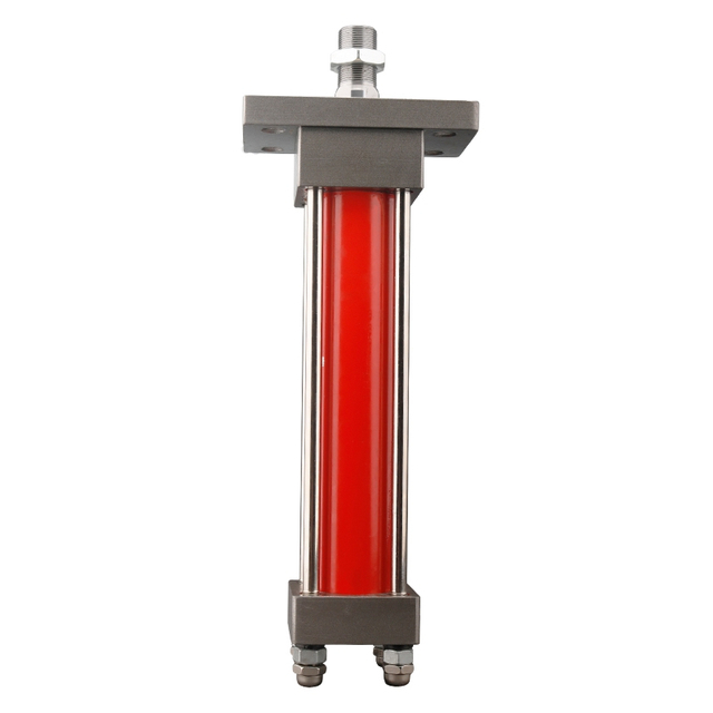
This guide compares two practical tie-rod cylinder families: the HOB series double-acting hydraulic cylinder and the MOB series 7 MPa hydraulic ram. It is not a claim that one series is universally better. It is a method for deciding whether the machine needs a heavier pressure envelope, a lighter industrial cylinder, a different rod, or a different cylinder architecture altogether.
Why the Series Name Is Not the First Question
The first question is not HOB or MOB. It is: what must the actuator do through the entire cycle?
Write down the load in both directions. Record the usable pressure at the cylinder ports, not only the relief-valve setting; the pressure-test-point guide shows why the measuring location changes the diagnosis. Measure the required travel and the time allowed for that travel. Note whether the rod pushes, pulls, holds a suspended load, or changes direction under inertia.
Then describe the installation. Is the cylinder fixed to a rigid machine base, pinned at both ends, mounted on feet, or attached through a flange? Does the linkage stay aligned, or does it sweep through an arc? Is the rod guided by the machine, or is the cylinder being asked to guide the load as well as move it?
The hydraulic cylinder installation guide is relevant here because a correct bore and stroke cannot rescue a mount that bends the rod or drags the piston against the barrel.
For field notes, one sentence is more useful than a copied model number:
The cylinder lifts a 28 kN fixture through a pinned linkage. Cap-end pressure reaches 9.5 MPa during the hardest 120 mm of a 600 mm stroke. The movement must finish in 5.5 seconds, and the rod is in compression while extending.
That note gives a supplier something to calculate. “Same as the old HOB80” does not.
The Short Answer: HOB or MOB?
BLINCE publishes the HOB hydraulic cylinder family as a heavy-duty, double-acting tie-rod cylinder with a pressure range of 0.3-14 MPa, bore sizes listed from 40-250 mm, and a maximum stated stroke of 5,000 mm. The page lists flange, rear-clevis/ear and foot mounting examples, while the visible standard size table covers common bore and stroke combinations.
The MOB 7 MPa cylinder page describes a light-type hydraulic cylinder. Its visible table lists bores from 30-125 mm and standard stroke rows from 50-1,000 mm, with double-rod, adjustable-stroke and mounting variations available by configuration.
Those published figures make HOB the more obvious starting point when the measured duty genuinely exceeds the MOB pressure envelope or when a larger bore and longer stroke are required. MOB can be the better purchase for moderate-pressure industrial motion where a lighter series already covers the force, speed, mounting and service needs.
Decision point
HOB starting point
MOB starting point
What still needs confirmation
Published pressure envelope
0.3-14 MPa
7 MPa series
Continuous duty, peaks, test pressure and exact configuration
Published bore coverage
40-250 mm family statement
30-125 mm visible table
Exact bore/rod pairing and availability
Published stroke information
Up to 5,000 mm stated
50-1,000 mm visible table
Buckling, sag, stop tube, support and mounting length
Typical purchasing reason
Higher force or heavier duty
Moderate-pressure industrial motion
Actual load and pressure at the cylinder
Main advantage
Broader pressure, bore and stroke envelope
Lighter series where 7 MPa is enough
Total installed cost and cycle requirements
Main trade-off
Can add cost, size and oil demand
Lower published pressure envelope
Whether the machine is under- or over-specified
Use this table as a screening tool, not a purchase order. A 14 MPa family is not automatically safer in a 7 MPa machine. A 7 MPa cylinder is not automatically too light when the measured load only needs 4.5 MPa.
Start With Force, Not Outside Diameter
For a double-acting cylinder, theoretical extension force is based on the full piston area:
F_extend = P x (pi x D^2 / 4)
Theoretical retraction force uses the annular area because the rod occupies part of the piston area:
F_retract = P x [pi x (D^2 - d^2) / 4]
Where:
F is theoretical force;
P is pressure at the working cylinder port;
D is piston bore;
d is rod diameter.
These equations do not include seal friction, pressure loss through the hydraulic valve and hoses, mechanical linkage losses, changing lever ratio, or acceleration. They are the beginning of selection, not the final rating.
The distinction matters because the main pump gauge may not show the pressure that reaches the actuator. The article on hydraulic pressure gauge placement explains why a reading at the pump outlet can stay high while pressure is being lost through a valve, coupler, filter, or return path.
Worked Example: 80 mm Bore, 45 mm Rod
Suppose a proposed cylinder has an 80 mm bore and 45 mm rod.
Full piston area:
A_piston = pi x 80^2 / 4 = 5,026.5 mm^2
Rod area:
A_rod = pi x 45^2 / 4 = 1,590.4 mm^2
Annular area:
A_annular = 5,026.5 - 1,590.4 = 3,436.1 mm^2
At 7 MPa, the theoretical extension force is about 35.2 kN, while theoretical retraction force is about 24.1 kN.
At 14 MPa, those theoretical values double to about 70.4 kN extension and 48.1 kN retraction.
The cylinder did not become physically larger. Pressure changed the theoretical force. In a real machine, however, you cannot simply raise the relief setting from 7 to 14 MPa. The pump, valve, hydraulic hoses and fittings, seals, frame, pins and guarded load all have to be rated and assessed for that pressure.
This is the first HOB-versus-MOB buying lesson: if 7 MPa already provides the required force with the approved design margin, a heavier series may add little value. If the actual cycle needs more than the MOB envelope, the answer may be HOB, a larger bore, a different linkage, or a redesign. It is not automatically “turn up the pressure.”
Bore Size Also Changes Oil Demand
A larger bore creates more force at the same pressure, but it needs more oil for each millimeter of travel.
Cylinder speed is approximately:
v = Q / A
Using the same 80 mm bore and a pump flow of 40 L/min, theoretical extension speed is roughly 133 mm/s. With the 45 mm rod, theoretical retraction speed is about 194 mm/s because the annular area is smaller.
A 600 mm extension would therefore take about 4.5 seconds before allowing for leakage, acceleration, valve metering and flow losses. Retraction would be faster if the same flow were available.
If the bore is increased without increasing pump flow, the cylinder slows. If the pump is enlarged to recover speed, the valve, port, hose and return line must carry the extra flow. The hydraulic pump and motor matching guide focuses on rotary actuators, but its central lesson applies here as well: useful flow has to survive the entire circuit.
Symptom after fitting a larger bore
Likely question
Test before changing another part
Extension is stronger but slower
Is pump flow unchanged?
Measure cylinder-port flow or timed stroke at working temperature
Pump reaches relief near end of stroke
Is the load or mechanical stop higher than expected?
Record pressure through the full travel
Return hose becomes hot
Is annulus-side return flow restricted?
Compare rod-port and tank-return pressure
Another function slows
Is available pump flow being shared?
Test each function alone and together
Motion becomes jerky
Is the valve metering range suitable for the new area?
Check spool opening, load change and trapped air
Do not use bore as a substitute for diagnosing low flow. A worn pump, blocked suction line, undersized valve or restrictive quick coupler can make a correctly sized cylinder look too small; the flow-control troubleshooting guide provides a useful test order before the bore is changed.
Rod Diameter Is a Structural Decision
Rod diameter changes retraction force, stiffness, buckling resistance, bearing pressure and the space available for threads or rod-end attachments.
A long rod that pushes a load behaves like a column. The longer the unsupported length and the less favorable the end conditions, the greater the buckling risk. A cylinder can have enough piston force to move the load and still have a rod that is structurally unsuitable for the stroke and mounting arrangement. The failure clues overlap with the side-load patterns covered in the cylinder installation article.
This is why a catalog bore-and-stroke match is not enough for a long-stroke press, lift, gate, platform or fixture. Parker's cylinder engineering guidance likewise treats long compression strokes, mounting style and rod-end guiding condition as part of rod selection rather than as separate details.
Check these items together:
maximum compressive load, including shock and inertia;
free rod length at maximum extension;
bore and rod diameter;
fixed or pivoted mounting condition;
whether the rod end is guided;
stop-tube or intermediate-support requirements;
side load created by the mechanism;
cylinder orientation and gravity load.
The published HOB maximum stroke of 5,000 mm does not mean every HOB bore, rod and mount can safely push every load through a 5,000 mm stroke. It means long-stroke configurations are within the family discussion; engineering confirmation still belongs to the exact load case.
Mounting Determines How the Load Reaches the Rod
Hydraulic cylinders are designed to push and pull along their centerline. They are poor substitutes for linear guides.
A clevis or trunnion mount can allow the cylinder to follow a changing linkage angle. A flange or foot mount can work well when the machine structure is rigid and accurately aligned. Trouble begins when mounting bolts are used to pull a misaligned cylinder into position, or when a fixed mount is used on a linkage that sweeps sideways. Persistent one-sided seal wear should therefore be compared with the symptoms in the hydraulic cylinder drift guide.
The HOB page lists mounting examples such as FA flange, CA rear ear/clevis, and LB foot mounting. These are not cosmetic ordering codes. Each one changes how reaction forces enter the machine frame.
Before selecting a mount, sketch the load path at three positions: fully retracted, mid-stroke and fully extended. If the pin centers do not remain in the same plane, the linkage needs articulation or external guidance. If the cylinder barrel becomes a lever against the mounting bolts, a larger bore will increase the damage.
Fixed Mounts: Advantages and Trade-Offs
Advantages
Compact installation when the machine frame is rigid.
Good centerline force transfer when alignment is controlled.
Flange and foot patterns can simplify industrial machine layouts.
Trade-offs
Less tolerant of angular change and frame distortion.
Misalignment can side-load the gland, piston and rod bearing.
Pipework and ports must not be used to pull the cylinder into place.
Pivot Mounts: Advantages and Trade-Offs
Advantages
Follow linkage rotation more naturally.
Common for mobile, lifting and articulated mechanisms.
Reduce bending when both pin joints remain aligned.
Trade-offs
Pins, bushings and brackets add clearance and wear points.
A loose pin can create impact at each direction change.
The mechanism still needs lateral guidance; a clevis does not control every side load.
Stroke Is More Than Travel Distance
Stroke tells you how far the piston can move. It does not tell you whether the replacement fits the machine when retracted or whether the rod end reaches the required point when extended.
For replacement work, record:
pin-to-pin or face-to-rod-end length when fully retracted;
required working stroke;
total extended length;
rod-end thread or eye dimensions;
port positions and orientation;
available clearance around tie rods and end caps;
space for hose movement;
required end-of-stroke deceleration.
Two cylinders with the same 80 mm bore and 500 mm stroke may have different closed lengths. One may fit between the pins but collide with the frame at full extension. Another may have the correct envelope but place the ports against a guard.
Do not increase stroke to “leave some extra.” If the mechanism reaches a hard stop before the cylinder finishes, the pump can remain on relief while the operator continues to command movement. If the cylinder reaches its internal end before the machine stop, repeated impact can damage the piston, gland, tie rods and mounts. That heat pattern can resemble the valve losses described in the directional-control valve selection guide.
End-of-Stroke Speed and Cushioning
A cylinder moving a light fixture at 30 mm/s is not the same job as a large bore moving a heavy mass at 200 mm/s.
Kinetic energy has to go somewhere when the movement stops. The machine may absorb it through external deceleration, a controlled valve profile, a cylinder cushion, or an undesirable metal-to-metal impact.
Ask whether cushioning is required at the cap end, rod end, both ends, or neither. Then define the actual moving mass, speed, orientation and cycle rate. A cushion that works during a no-load shop test may be inadequate when the fixture carries production load.
Do not close a cushion adjustment until the cylinder barely moves. Excessive restriction can create pressure spikes and heat. If a valve meters the motion, its flow range and pressure compensation also matter; the flow-control valve speed guide explains why a stable handle position does not always produce stable actuator speed.
Pressure Rating Is Not the Same as Working Pressure
The relief-valve setting, pump maximum, cylinder family rating and pressure seen during a real cycle are four different numbers.
A machine may operate at 6 MPa most of the time and spike higher when a heavy fixture starts moving. Another machine may hold 10 MPa continuously for several minutes. The peak number alone does not describe fatigue, heat or seal loading, which is why the pressure gauge placement article recommends recording the real operating cycle rather than one isolated reading.
Before using the HOB 14 MPa envelope or the MOB 7 MPa label, ask for the exact configuration's working, peak and test limits. Confirm whether the published pressure applies across the selected bore, rod, mount and stroke. Then compare it with measured pressure at both cylinder ports under the real load.
A liquid-filled hydraulic pressure gauge can make field readings easier under vibration, but range selection matters. A 40 MPa gauge is a poor instrument for setting a circuit that normally works near 4 MPa because the useful part of the scale is compressed.
The Valve Can Make the Correct Cylinder Behave Incorrectly
A double-acting cylinder depends on a directional valve to supply one side and open a return path from the other. The spool center also decides what happens in neutral: ports may be blocked, connected to tank, or arranged for a specific load-control function.
If a replacement cylinder creeps, stalls, chatters or moves differently in one direction, do not assume the bore is wrong. Check whether the directional control valve has the required flow capacity and center condition. Measure pressure at both work ports while the symptom occurs.
Load-holding valves deserve separate attention. A counterbalance valve or pilot-operated check can protect a suspended or overrunning load, but it also changes pilot pressure, return pressure and release behavior. Selecting a larger cylinder changes the area ratio and may change how the load-control valve behaves.
Never treat a standard directional spool as the only safety device for a suspended load. The final circuit must follow the machine manufacturer's safety design and applicable requirements.
Ports, Hoses, and Fittings Decide Whether Flow Reaches the Cylinder
The cylinder port thread proves that a fitting can be installed. It does not prove that the internal passage can carry the required flow with acceptable pressure loss.
A larger bore may need more flow to meet the same cycle time. If the existing hose, elbow or coupler remains small, the machine can gain theoretical force and lose practical speed. The return side can be especially misleading because retraction or extension may displace oil from a different effective area. The pump-and-motor matching article uses the same pressure-drop logic for rotary circuits.
The broader hydraulic hoses and fittings range should be selected by line function, pressure, flow, bend radius and movement, not by thread alone. Where a hose change has already made the cylinder slow, compare pressure before and after the changed assembly at the same load.
Keep hose loads away from the cylinder port. A short hose forced sideways can apply a continuous bending moment to the port block or end cap. Use the correct fitting angle and enough free length for movement without rubbing or kinking.
Temperature, Seals, and Oil Cleanliness
The seal package must match the hydraulic fluid, minimum and maximum oil temperature, speed, pressure, surface finish and environment.
Cold oil raises resistance and can make the first cycles slow. Hot oil reduces viscosity and can expose internal leakage that was not obvious at startup. A cylinder that holds a load cold but drifts after 40 minutes may have worn piston seals, valve leakage, or both; the wider cleanup and oil-path checks are set out in the hydraulic contamination control guide.
The hydraulic cylinder drift guide separates internal cylinder leakage from valve and load-control problems. That distinction matters before ordering a larger replacement.
Contamination changes the purchasing decision too. A new cylinder installed into dirty oil can lose seals and barrel finish quickly. If the previous cylinder produced metal or seal debris, inspect the reservoir, filters, hoses and valve passages before commissioning the replacement. The hydraulic contamination control guide gives the wider cleanup sequence.
Equipment-Specific Checks
Industrial Presses and Fixtures
Presses often tempt buyers to choose from tonnage alone. The required force matters, but so do daylight, closed length, frame stiffness, approach speed, pressing speed, dwell time and return speed.
MOB may suit moderate-pressure clamping or positioning where its 7 MPa series data covers the duty. HOB can become the better starting point when the verified force and pressure demand is higher. Neither should be selected until the press frame and guarded process are confirmed for the load.
Injection Molding and Production Machinery
Cycle repeatability and end-of-stroke behavior matter more than a single maximum-force test. Check oil temperature after production stabilizes, not after three dry cycles. If a cylinder changes speed as the oil warms, inspect valve metering and internal leakage before increasing bore, using the flow-control valve guide as a diagnostic companion.
Agricultural and Mobile Equipment
Outdoor machines see dust, water, shock, loose pins and frame movement. Tie rods, rod chrome, wipers, hoses and mounts all live in that environment. A cylinder that is satisfactory on a clean indoor fixture may need different protection on a loader, harvester or attachment.
For articulated loads, inspect pin alignment through the complete movement. Do not let the cylinder act as the guide for a worn linkage.
Long-Stroke Lifts and Gates
Long stroke makes rod buckling, sag, support and hose routing central to selection. A family maximum stroke is not a buckling approval. Send the load direction, mounting arrangement and fully extended geometry for review.
If the load can fall or overrun, load control and mechanical safety measures must be designed with the cylinder. A larger bore by itself does not make the lift safer.
Who Should Not Buy HOB or MOB Yet?
Do not release an order for either series if the only known information is bore and stroke.
Pause the purchase when:
the load is suspended and the load-holding circuit has not been identified;
the rod works in long-stroke compression but buckling has not been checked;
the machine linkage applies visible side load;
the pressure figure comes only from the pump nameplate;
the requested cycle time is unknown;
the old cylinder failed repeatedly but the mount and oil were not inspected;
the required pressure is outside the selected series envelope;
the application needs a telescopic, welded-body, mill-duty or position-sensing cylinder instead of a standard tie-rod design;
the buyer expects a drop-in replacement without confirming closed length, ports and mounting dimensions.
HOB and MOB are also poor buying shortcuts for anyone trying to cure a weak pump, restrictive valve or blocked return line with a larger actuator.
Practical Checklist Before Requesting a Quote
Information to send
Why it changes the recommendation
Machine and function
Defines duty, environment and consequences of failure
Push and pull load
Determines required force in each direction
Pressure at both cylinder ports
Separates useful pressure from pump-side readings
Bore and rod diameter
Determines areas, force ratio and stiffness
Stroke and closed length
Confirms travel and installation envelope
Required extension/retraction time
Converts travel into flow demand
Mounting type and pin dimensions
Defines load path and interchangeability
Rod-end thread or eye
Confirms mechanical connection
Port thread, position and orientation
Controls plumbing and clearance
Fluid and temperature range
Guides seal and material selection
Cycle rate and duty duration
Reveals heat and fatigue exposure
Load orientation and side-load risk
Drives rod, bearing and mount review
Cushioning requirement
Controls end-of-stroke energy
Photos or drawing
Reveals geometry that a model number misses
Failure history
Prevents repeating the original cause
If several values are unknown, a preliminary recommendation is still possible. It should be labeled preliminary. The fewer unknowns, the lower the risk of buying a cylinder that fits the pins but misses the job.
Common Buying Mistakes
Mistake 1: Choosing HOB Only Because 14 MPa Is Higher
Higher published pressure is useful only when the machine needs it and the full system is rated for it. In a moderate-pressure fixture, MOB may already meet the duty with lower size or cost.
Mistake 2: Choosing MOB Because the Old Cylinder Worked at 7 MPa
The old cylinder may have had a different bore, rod, mount, seal package or duty. Confirm the complete geometry and load before copying the pressure label.
Mistake 3: Increasing Bore Without Checking Pump Flow
Larger bore increases force but slows the cylinder at the same flow. A rushed “upgrade” can miss production cycle time.
Mistake 4: Ignoring Retraction Force
The rod reduces the effective area. A cylinder that pushes the load successfully may not have enough pull force for the return stroke.
Mistake 5: Ignoring Buckling on a Long Push Stroke
Piston force can exceed rod column strength. Check rod diameter, free length, mount and guiding condition.
Mistake 6: Treating the Cylinder as a Linear Guide
Side load damages the rod bearing, gland, seals and barrel. Guide the machine load separately and keep force on the centerline.
Mistake 7: Copying Stroke but Not Closed Length
Equal stroke does not guarantee equal pin-to-pin dimensions or port clearance.
Mistake 8: Fitting a Larger Cylinder to the Same Small Valve
The cylinder may be strong but slow. Check flow capacity and pressure drop across the valve, hoses and fittings.
Mistake 9: Installing the Replacement Into Dirty Oil
Old seal material and metal can damage the new cylinder. Clean and inspect the oil path after a component failure.
Mistake 10: Treating a Catalog Maximum as a Complete Engineering Approval
Maximum bore, stroke and pressure belong to a product family. Exact configuration, mount, rod and duty still need confirmation.
A Quote Request That Gives the Supplier Something to Check
Avoid sending only:
Quote HOB80 x 600, same as photo.
Use a technical note:
The cylinder operates a pinned lifting linkage on an indoor production fixture. Required stroke is 600 mm and retracted pin-to-pin length is 930 mm. The load is 28 kN at the hardest linkage position. Measured cap-port pressure is 9.5 MPa and rod-port return pressure is 0.7 MPa. Required extension time is 5.5 seconds. Existing bore is 80 mm, rod is 45 mm, and the rod works in compression while extending. Rear clevis and threaded rod eye dimensions are shown in the attached drawing. Oil reaches 58 degrees C during an eight-hour shift. The old rod has one-sided wear near the gland.
That request lets a supplier challenge the selection. The one-sided wear may point to alignment. The 9.5 MPa working condition may rule out a 7 MPa series. The extension time sets a flow target. The compressed long rod calls for a buckling check.
For BLINCE selection support, start with the hydraulic cylinder product range, then send the drawing, load, pressure, speed, mounting and failure history rather than relying on the series name alone.
FAQ
What is a tie-rod hydraulic cylinder?
A tie-rod cylinder is held together by external rods running from the head to the rear cap. That layout makes the unit relatively straightforward to dismantle and service. The series drawing remains the authority for pressure, bore, rod, stroke and mounting dimensions; the construction name does not settle any of them.
How do HOB and MOB tie-rod cylinders differ in practice?
In the BLINCE catalogue, HOB occupies the heavier end of the tie-rod range and is listed for 0.3-14 MPa. MOB is the lighter 7 MPa family. HOB also extends across a wider published bore and stroke range. None of that makes the decision automatic: a machine working comfortably below 7 MPa may gain nothing useful from the larger catalogue limits.
Is HOB always better than MOB?
Not as a general rule. If the measured load can be handled within 7 MPa and the MOB dimensions suit the mount and cycle, MOB may be the cleaner choice. HOB earns its place when the duty genuinely needs its broader envelope. Buying extra bore or pressure capacity also brings extra oil demand and cost; the machine does not improve merely because the catalogue number is higher.
What force does an 80 mm bore produce at 7 and 14 MPa?
Start with the area: an 80 mm bore gives approximately 5,026.5 mm2. Multiplying that figure by pressure gives about 35.2 kN at 7 MPa, or 70.4 kN at 14 MPa, for theoretical extension. A field result will be lower because seals, line losses and the machine linkage consume part of that force.
Why is cylinder pull force lower than push force?
On the return stroke, the rod has already taken up part of the useful piston area. Oil therefore works on the ring-shaped area around the rod, not on the complete 80 mm circle. With pressure unchanged, less area means less theoretical pulling force.
Does increasing the cylinder bore increase its speed?
Usually the reverse. Every millimeter of travel in a larger bore requires a greater volume of oil. Keep pump flow unchanged and travel time increases, even though the cylinder can generate more theoretical force at the same pressure.
Is a 14 MPa cylinder a drop-in replacement for a 7 MPa unit?
It can be possible, but the higher rating proves only that the candidate cylinder has a different pressure envelope. It says nothing about closed length, rod size, mounting holes, ports, cushioning or oil demand. Those details still have to match, and the circuit will continue to develop pressure in response to its load and controls.
How do I choose hydraulic cylinder stroke?
Match the required machine travel while confirming fully retracted and extended dimensions. Avoid using the cylinder's internal end stops as the normal machine stops unless the design specifically allows it.
When does rod buckling become a concern?
Buckling becomes important when the rod pushes a load over a long unsupported length. Load, rod diameter, stroke, mounting, guiding and end conditions must be evaluated together.
Why does a new cylinder leak at the rod seal?
Possible causes include side load, bent rod, damaged chrome, contamination, wrong seal material, excessive return pressure, poor installation or genuine seal damage. Inspect the failure pattern before replacing the seal again.
What information is needed for a hydraulic cylinder quotation?
Send machine function, load, working pressure, bore, rod, stroke, closed length, mounting, pin or thread dimensions, ports, cycle time, fluid, temperature, duty cycle, photos or drawings, and the old failure history.
Should a suspended load rely on the directional valve to hold position?
Not by default. Suspended and overrunning loads may require purpose-designed load-holding valves and mechanical safety measures. Follow the machine manufacturer's circuit and applicable safety requirements.
What the Purchase Decision Comes Down To
HOB versus MOB is not a contest between a stronger cylinder and a weaker one. It is a choice between two product envelopes.
MOB can be a sensible fit when a 7 MPa light-type tie-rod cylinder meets the verified force, speed, mounting and duty. HOB becomes the stronger candidate when the application needs a higher working-pressure envelope, larger bore, longer stroke or heavier-duty configuration.
The deciding information remains outside the series name: pressure at the cylinder, force in both directions, pump flow, rod stability, mounting alignment, port restriction, oil temperature and the way the load behaves at the ends of travel.
For a review, send BLINCE the cylinder drawing or clear photos, bore, rod, stroke, closed length, mounting dimensions, port details, measured working pressure, cycle time, oil temperature and failure history. The goal is not merely to supply a cylinder that bolts in. It is to select a double-acting hydraulic cylinder that matches the machine before the next failure becomes part of the specification.
Research Notes
BLINCE HOB and MOB product data were used for product-family pressure, bore, stroke and mounting references.
Parker and Danfoss cylinder engineering resources were consulted for general selection principles involving force, speed, mounting, serviceability and rod buckling.
Calculated force and speed examples are theoretical screening values, not certified performance data for a specific supplied cylinder.
This article is a general engineering guide. Final component selection should be based on machine drawings, measured hydraulic data, working conditions, safety requirements, and confirmation from a qualified hydraulic engineer or supplier.
Blince Hydraulic Team
Blince Hydraulic is an industry-leading company dedicated to precision-engineered fluid power manufacturing and custom hydraulic solutions. Backed by decades of deep field expertise in industrial machinery and thousands of successful global deployments, our engineering team focuses entirely on high-performance hydraulic component manufacturing, including specialized orbital motors, high-pressure travel drives motor, and robust directional control valves. Our production infrastructure utilizes state-of-the-art multi-axis CNC machining systems and is fully ISO 9001 certified to guarantee repeatable volumetric accuracy across every single manufacturing run.
We deliver fast, highly dependable, and cost-efficient hydraulic solutions to heavy industry distributors, machinery OEMs, and maintenance crews across more than 150 countries. Whether your active project calls for a small-volume batch of customized shaft profiles or a large-scale production run of severe-duty cast iron gear pump, we configure our flexible production schedules to meet your target lead times with total pricing predictability. Partnering with Blince means securing maximum system efficiency, elite material quality, and uncompromised fluid power professionalism.
To learn more about our complete product lineup, visit our official website: www.blince.com.