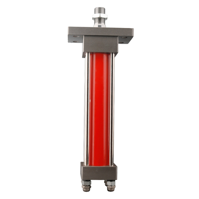
A replacement cylinder can have the correct bore, stroke and pressure rating and still fail early because its mount puts the rod under bending. That mistake often begins with a drawing that shows only pin-to-pin length. The missing details—pivot plane, load direction, trunnion position, flange face or foot height—decide how force reaches the machine frame.
Short answer: choose a hydraulic cylinder mounting type from the motion and load path. Use a fixed centerline mount, such as a flange, when the load travels straight and the frame can hold precise alignment. Use a clevis, rear eye or trunnion when the cylinder must follow an arc in one plane. Foot and side mounts can simplify packaging, but their support plane is offset from the cylinder centerline, so the machine structure must resist the resulting moment. A spherical bearing can accommodate limited angular movement; it does not repair poor linkage geometry.
Selection boundary: the mount controls how force enters the structure. It does not, by itself, establish bore, rod diameter, stroke, pressure capability, buckling margin, pin strength or interchangeability.
What are the main hydraulic cylinder mounting types?
Hydraulic cylinder mounts fall into three working groups: fixed centerline mounts, fixed offset mounts and pivot mounts. Flanges and extended tie rods are centerline examples; feet and side lugs are offset examples; clevises, eyes and trunnions are pivot examples. The correct group follows the load path and linkage motion, not the name of the machine.
Parker's cylinder-selection guide uses the same three fundamental categories. Its practical rule is that the mounting arrangement should absorb force on the cylinder centerline. Parker also advises considering whether the cylinder pushes or pulls, how fast it moves and whether the load path is fixed or pivots.
Mount family
Common forms
Motion it should accommodate
Main advantage
Main engineering concern
Fixed centerline
Cap flange, head flange, extended tie rods
Straight
Direct load transfer and high rigidity
Frame and cylinder axes must stay aligned
Fixed offset
Foot, side lug, side tap
Straight
Packaging access and convenient support surface
Offset load creates a moment and fastener shear
Pivot at one end
Rear clevis, rear eye, spherical eye
Arc in one principal plane
Simple linkage connection
Pin, bushing, clearance and out-of-plane motion
Pivot along the body
Head, cap, intermediate or center trunnion
Arc about the trunnion axis
Compact envelope and selectable pivot location
Bearing-block alignment and trunnion-pin bending
The table is a selection map, not a dimensional standard. A “clevis mount” from two suppliers may have different pin diameters, clevis gaps, center heights and closed lengths. A standard family designation is needed when dimensional interchangeability matters. For example, ISO 6020-2:2015 defines mounting dimensions for a specific metric compact, single-rod 16 MPa cylinder family. It does not make every metric cylinder interchangeable.
Begin with two questions: straight travel or an arc, push or pull?
Sketch the cylinder at both ends of its stroke. Connect the cap-end pin, rod-end pin and machine pivot points. If the rod-end connection follows an arc, at least one cylinder connection must rotate with that arc. Locking both ends to rigid brackets does not make the linkage straight; it transfers the geometric error into the rod, gland, pins and frame.
Next mark the dominant force direction. A cylinder that primarily pushes puts the rod in compression and may need a buckling check. A cylinder that primarily pulls puts the rod in tension, but the mounts and pins still see the full load. Parker's general selection guidance favors cap-end mounting for a compression/push duty and head-end mounting for a tension/pull duty because this shortens the stressed load path. Packaging or linkage constraints can lead to another arrangement, but the designer should then calculate the consequences rather than assume equivalence.
Speed changes the picture. Clearance that causes little trouble in a slow fixture can become an impact at each reversal in a fast-cycling machine, alternately loading the two pin-bearing faces. Pressure spikes may also load the mount well beyond the steady gauge reading. Static force alone is not enough for shock, high cycle count or an over-running load.
Fixed centerline mounts: flange and extended tie rods
When a flange mount is the cleanest load path
A flange places the supporting face near the cylinder centerline and transmits thrust into a rigid bulkhead or machine member. It is often a strong choice for presses, clamps, gates and linear actuators whose load stays on one axis. A cap flange is usually the more direct arrangement for a push load; a head flange can suit a pull load.
A flange is only as good as the frame behind it. A thin plate can flex enough to misalign a correctly machined cylinder, so the mounting face must remain flat, stiff and square to the travel axis under load. Bolt grade, engagement, preload, edge distance and flange-face contact require a drawing-level structural check.
Flange mounting also trades service access for rigidity. A rear bulkhead may hide ports or make seal access difficult. A front flange may consume rod-end space. These are packaging costs, not reasons to accept alignment error.
Extended tie-rod mounting
An extended tie-rod mount can transfer force close to the centerline while keeping the cylinder removable. It is common on industrial tie-rod cylinders and lets the machine designer support the cap end, head end or both according to the series drawing. The tie rods and mounting nuts are part of the cylinder structure, so substitutions, added spacers and nonstandard nut locations should be reviewed by the manufacturer.
Parker's Miller Series catalogue describes tie-rod and flange arrangements as centerline supports and stresses rigid alignment. Its dimensional tables are specific to those Parker series. They are evidence for the load-path principle, not dimensions for another brand.
Fixed offset mounts: foot and side mounting
Foot or side mounts can be practical when a cylinder must sit on a base plate, remain accessible from above or fit beside the driven member. The tradeoff is mechanical: the mounting plane sits below or beside the line of force. That offset creates a moment as the cylinder develops thrust.
Imagine pushing a door near the hinge rather than through its center. The force is real in both cases, but the offset changes what the attachment must resist. On a side-mounted cylinder, friction at the mounting surface, bolt preload, keys, dowels and frame stiffness share the reaction. If the joint slips, bolts can see repeated shear and the cylinder axis can move.
For heavy or shock duty, cylinder catalogues often show keys or pins intended to locate the mount. Do not improvise their position. The Schrader Bellows application-engineering pages note that non-centerline frames must withstand the developed moment and discuss keyed or pinned side mounts. They also warn against restraining thermal expansion incorrectly. The exact key dimensions and restraint method belong to the selected series and machine drawing.
Choose a foot or side mount when the frame has been designed for this offset path, not merely because a base bracket is easy to fabricate. Check these items before approval:
distance from cylinder centerline to mounting plane;
direction of peak thrust and whether it reverses;
base-plate thickness, welds, bolts, keys and contact surface;
access for tightening and inspection;
thermal growth and which features locate versus clamp the cylinder;
deflection at the rod-end connection across the full stroke.
Pivot mounts: clevis, rear eye and spherical bearing
Hydraulic cylinder clevis mount
A clevis uses a pin through two cheeks and a mating eye. It allows the cylinder to rotate about the pin axis, making it suitable for a linkage that follows an arc in one plane. Common applications include dump bodies, doors, tilting platforms, agricultural linkages and material-handling mechanisms.
The words “in one plane” are important. A plain clevis cannot freely correct twist or a second-axis angular error. If the machine brackets are not parallel, the pin may bind and the cylinder can be forced sideways. A worn pin or elongated hole adds impact at reversal; tightening the fit without correcting bracket alignment can replace impact with binding.
For a replacement, record more than the pin diameter. Measure the clevis gap, cheek thickness, bushing width, pin length, center height, retracted center-to-center length and extended center-to-center length. Note whether the pin is retained by a clip, bolt, plate or threaded feature. Photograph the connection from two directions with the machine mechanically supported.
Rear eye and spherical eye
A plain rear eye behaves like a single lug and normally pivots around one pin axis. A spherical bearing eye can accommodate a limited amount of angular movement, which may be useful where the linkage has small unavoidable misalignment. Its permitted angle, radial load, axial load, lubrication and oscillation life come from the bearing and cylinder manufacturer.
Do not use a spherical eye as a universal cure. If the linkage path is genuinely multi-plane, the joint arrangement must be designed for multi-axis movement. Some catalogues publish small permissible angles for particular spherical-bearing mounts, but those values are series-specific. Copying an angle from an unrelated catalogue is not an engineering limit for the selected cylinder.
Hydraulic cylinder trunnion mount
A trunnion mount places two cylindrical journals on or near the cylinder body. Bearing blocks support those journals so the cylinder rotates about a fixed transverse axis. Head, cap, center and intermediate trunnions let the designer position that axis to suit the linkage and available envelope.
Because its pivot does not sit beyond the cap, a trunnion can fit an envelope that has no room for a rear clevis. Moving that pivot also changes the effective unsupported length and the cylinder's swept path. The two bearing blocks, however, must be coaxial, correctly spaced and close enough to the trunnion shoulders to avoid bending the journals.
The trunnion is intended to rotate in its bearings and carry shear. A wide unsupported gap can turn it into a bending pin. Misaligned bearing blocks can clamp the body or load one journal more heavily than the other. Before release, check the manufacturer's drawing for journal diameter, shoulder spacing, bearing width, lubrication, axial retention and permitted mounting tolerances.
Clevis vs trunnion: which is better?
Choose a clevis when a rear pivot is acceptable, the linkage rotates mainly in one plane and a pin-and-bushing connection is easy to inspect. Choose a trunnion when the cylinder needs to pivot about a point along its body or the envelope cannot accommodate a rear pivot. Neither is inherently stronger. Strength and life depend on the selected dimensions, support geometry, pressure, force, shock and cycle count.
Decision
Rear clevis / eye
Trunnion
Pivot position
Usually beyond the cap
On or along the cylinder body
Packaging
Adds rear length
Can shorten the rear envelope
Support parts
Pin, lugs and bushing
Two aligned bearing blocks and journals
Common wear point
Pin/bushing and lug holes
Trunnion bearings and journal shoulders
Alignment sensitivity
Bracket parallelism and pin axis
Coaxial bearing blocks plus pin axis
Best use
Simple one-plane linkage
Compact one-plane pivot with controlled pivot location
Why mounting errors become side load
Hydraulic cylinders are efficient at carrying axial tension or compression. A side reaction makes the rod contact the gland or bearing unevenly and can add bending to the rod. Symptoms may include asymmetric bearing wear, polished marks on one side of the rod, recurring seal leakage, pin wear, squeal, slow spots or a cylinder that moves freely only when disconnected from the mechanism.
Side load can come from several sources: fixed brackets on an arc-moving linkage, nonparallel clevis ears, offset machine loading, a flexible flange plate, trunnion blocks that are not coaxial, bent structure, worn pins or a base that shifts under load. Enerpac's lifting-cylinder safety instructions likewise identify eccentric loading, misalignment, shifting centers of gravity, unsynchronized lifting and unstable bases as side-load causes. That document covers high-tonnage lifting equipment, so its operating rules should not be treated as a BLINCE cylinder datasheet.
Worked example: force and a simplified angular component
Consider an 80 mm bore cylinder extending at 100 bar. Convert 100 bar to 10 MPa:
A = πd⊃2;/4 = π × (0.08 m)⊃2;/4 = 0.005027 m²
F_ideal = pA = 10,000,000 Pa × 0.005027 m² = 50,265 N ≈ 50.3 kN
The result is ideal extension force. It excludes rod-side back pressure, seal friction, flow losses and pressure transients.
Now use a hypothetical 2° mismatch only to show how a large axial force can produce a nontrivial transverse component:
This 1.75 kN is a simplified vector illustration, not the actual gland side load and not an allowable misalignment value. Real reaction forces depend on what constrains the cylinder, the lever arms, bracket stiffness, pin clearance, friction, acceleration and pressure spikes. Two degrees may be unacceptable in one assembly and may be accommodated by a rated joint in another. Use the selected cylinder, bearing and linkage data to set limits.
Worked example: why pin diameter alone is not enough
If the same 50.3 kN were carried by a 30 mm pin in ideal double shear:
That number does not approve the pin. It omits pin bending, bearing pressure in the lugs and bushing, distance between supports, material yield and fatigue strength, stress concentration, shock, corrosion, lubrication and wear. A loosely supported pin can fail in bending even when a simple double-shear average looks modest.
Flange vs foot mount: the useful tradeoff
A flange usually gives the cleaner axial load path. It asks for a stiff, square bulkhead and may limit service access. A foot mount often improves access and lets the cylinder sit on a base, but the offset between the force line and base produces a structural moment. The correct choice is the one the machine frame is designed to carry.
Cylinder price is a poor comparison by itself. Include the bulkhead, keys, machined faces, bearing blocks, service access and eventual pin replacement; the lower-priced mount may demand the more expensive machine structure.
Mounting checks by application
Press, clamp or straight linear fixture
A flange or centerline tie-rod mount is usually the first concept when the driven platen or slide stays on guides. Verify that the guides, not the cylinder rod, resist side force. For a long push stroke, perform a rod-buckling calculation using the actual end conditions and unsupported length.
Dump body, boom or tilting platform
The cylinder ends follow changing angles. Clevis, eye or spherical-bearing connections are common, but the linkage drawing must confirm the motion plane and angle throughout the stroke. Check over-center positions, interference, hose bend radius and load variation as the lever arm changes. Mechanically support raised equipment before inspection.
Compact transfer or oscillating mechanism
A trunnion can place the pivot near the cylinder body and save rear space. Model the swept envelope at retracted, mid-stroke and extended positions. Keep the bearing blocks aligned and close to the trunnion shoulders according to the selected drawing.
Side-mounted industrial actuator
A foot or side-lug mount can keep ports and tie rods accessible. Design the base to carry the offset moment, and use the locating method specified for the series. Check that weld distortion or base deflection does not change the cylinder axis after assembly.
How BLINCE cylinder families enter the selection
The mount is only one layer of the selection. Bore, rod diameter, stroke, operating pressure, ports, seals, speed, environment and duty cycle still have to match the application. The BLINCE hydraulic cylinder range provides the product-family starting point; a project drawing should control the final choice.
The BLINCE HOB double-acting tie-rod cylinder is presented on its public page as a heavy-duty family with 40–250 mm bores, a published 0.3–14 MPa range and strokes up to 5000 mm. The page lists options including FA flange, CA rear-ear and LB foot forms. These are catalogue boundaries, not a promise that every combination is suitable or immediately available; confirm the current datasheet and project geometry.
For lighter industrial duties, the BLINCE MOB Series 7 MPa hydraulic ram is described as a light-type family with mounting and customization options. The application pressure, load, stroke, rod size and mounting drawing still decide whether MOB is appropriate.
An HSG Series hydraulic cylinder or a custom cylinder may fit mobile or machinery-specific geometry that does not map cleanly to an industrial tie-rod pattern. BLINCE should compare the drawing and duty data before recommending a family.
Replacement-cylinder measurement checklist
Do not remove a load-bearing cylinder until the machine is mechanically supported, isolated and depressurized under the equipment manufacturer's procedure. Once safe, collect the following:
Machine function and whether the cylinder pushes, pulls or does both.
Maximum working pressure, relief setting and known pressure spikes.
Required force in each direction or the load and linkage geometry needed to calculate it.
Bore, rod diameter and stroke, if known.
Fully retracted and fully extended mounting-center distances.
Mount style and its code from the original drawing or nameplate.
Clevis/eye pin diameter, width, gap, center height and retention method.
Trunnion diameter, shoulder-to-shoulder spacing, axial location and bearing-block dimensions.
Flange thickness, pilot or register diameter, bolt-circle pattern, hole size and face location.
Foot or side-mount hole pattern, base-to-centerline height and locating key/dowel details.
Rod-end thread, clevis, eye or spherical-bearing dimensions.
Port thread, size, orientation and clearance for fittings and hose movement.
Swept envelope and articulation angle at retracted, mid-stroke and extended positions.
Cycle rate, speed, dwell time and expected annual cycles.
Fluid, temperature, contamination level, outdoor/corrosive exposure and washdown requirements.
Photos from the side and above, plus the machine and cylinder nameplates.
A steel rule in a photograph helps the reviewer understand scale, but it is not a measured dimension. Label every value as drawing-derived, directly measured or estimated. Mixing those sources without labels is how a replacement can arrive with the right stroke and the wrong installed length.
Common mistakes that shorten cylinder life
Copying only pin-to-pin length
Two cylinders can share a retracted center distance and still have different strokes, extended centers, port positions, clevis gaps or trunnion locations. Match the complete drawing.
Making a clevis joint rigid
Overtightened cheeks, misaligned spacers or a seized bushing can prevent the intended pivot. The linkage then tries to bend the rod as it moves through the arc.
Expecting a spherical bearing to absorb any error
Spherical bearings have finite angles and load ratings. They can accommodate a designed small angular movement, not structural twist or an incorrectly located pivot.
Supporting trunnions too far from their shoulders
An excessive bearing-block gap increases journal bending. Follow the selected series drawing and check the support structure under load.
Letting mounting bolts locate and carry repeated shear by themselves
Some side-mounted arrangements need keys or pins. Use the manufacturer's intended locating method and calculate the frame joint; do not add an arbitrary dowel that conflicts with thermal growth or service removal.
Using the rod as a machine guide
The cylinder should provide axial force. Linear bearings, rails or the linkage should control lateral motion. A new seal will not fix a rod that is being forced sideways by the machine.
Assuming the catalogue maximum applies to every mount and duty
Maximum pressure or stroke on a product page does not confirm buckling, speed, cushioning, fatigue or mounting suitability for a particular configuration. Ask for the current dimensional drawing and application review.
When not to select from a web guide
Stop and request engineering review when the linkage moves in more than one plane, the original structure is bent or cracked, pin holes are elongated, forces or pressure spikes are unknown, the cylinder has a long compression stroke, or the actuator lifts/holds a load whose release could injure someone. The same caution applies when a replacement changes bore, rod diameter, operating pressure, mount location or port orientation.
A safety-critical lift or load-holding system may need mechanical locks, rated load-holding valves, hose-burst protection, redundancy and jurisdiction-specific compliance. Mount selection is not a substitute for the machine risk assessment.
Send BLINCE the original drawing if available, clear photos, bore, rod, stroke, retracted and extended centers, mount dimensions, pin or trunnion details, port information, pressure, forces, motion arc, cycle rate, fluid, temperature and quantity. Mark which dimensions are verified and which are estimates.
BLINCE can compare HOB, MOB, HSG and custom-cylinder routes and identify missing quote data. Final suitability remains subject to the confirmed datasheet, machine structure and application engineering. Contact BLINCE with your cylinder drawing and operating data.
Frequently asked questions
What is the best hydraulic cylinder mounting type?
There is no universal best mount. A flange or extended tie-rod mount is usually the first choice for a straight, rigid and accurately aligned load path. A clevis, eye or trunnion suits a linkage that rotates in one plane. Foot and side mounts are appropriate when the frame is designed for their offset moment.
What is the difference between a clevis mount and a trunnion mount?
A clevis pivots around a pin at the cylinder end, usually behind the cap. A trunnion pivots around journals positioned on or along the cylinder body. Clevis mounts use pin-and-lug support; trunnions require two coaxial bearing blocks. Both normally pivot in one plane.
Can a hydraulic cylinder clevis move in two planes?
A plain clevis is a one-axis joint. It should not be expected to follow a multi-plane path. A rated spherical bearing can permit limited angular movement, but its angle and load limits must come from the selected product documentation.
Does a flange mount prevent side load?
No. A flange provides a direct centerline load path only when the mounting face and guided load remain aligned and stiff under force. A flexible bulkhead, mislocated rod-end bracket or poorly guided load can still bend the rod.
How much side load can a hydraulic cylinder accept?
There is no safe universal percentage. Allowable side load depends on the cylinder's bearing design, rod size, stroke, extension, speed, mounting, moment arm and duty cycle. Obtain the manufacturer's rating or redesign the guides and linkage so the cylinder carries axial force.
Are hydraulic cylinder mounts standardized?
Some mounting dimensions are standardized within defined cylinder families, such as ISO 6020-2 compact metric 16 MPa cylinders. The family, nominal size and mount code must match. Calling both cylinders “flange mount” or “clevis mount” does not prove dimensional interchangeability.
What dimensions are needed for a replacement clevis cylinder?
At minimum, record bore, rod, stroke, retracted and extended pin-center distances, pin diameter, clevis gap and width, rod-end dimensions, port thread and orientation, pressure, force direction and articulation plane. Add duty cycle, environment, photos and the original drawing when available.
Should the cylinder rod guide the machine load?
No. The rod transmits axial force; the machine's rails, bearings or linkage should control lateral motion. Using the rod as a guide increases bearing wear, seal leakage risk and bending stress.
This article is a general engineering guide. Final component selection should be based on machine drawings, measured hydraulic data, working conditions, safety requirements, and confirmation from a qualified hydraulic engineer or supplier.
Blince Hydraulic Team
Blince Hydraulic is an industry-leading company dedicated to precision-engineered fluid power manufacturing and custom hydraulic solutions. Backed by decades of deep field expertise in industrial machinery and thousands of successful global deployments, our engineering team focuses entirely on high-performance hydraulic component manufacturing, including specialized orbital motors, high-pressure travel drives motor, and robust directional control valves. Our production infrastructure utilizes state-of-the-art multi-axis CNC machining systems and is fully ISO 9001 certified to guarantee repeatable volumetric accuracy across every single manufacturing run.
We deliver fast, highly dependable, and cost-efficient hydraulic solutions to heavy industry distributors, machinery OEMs, and maintenance crews across more than 150 countries. Whether your active project calls for a small-volume batch of customized shaft profiles or a large-scale production run of severe-duty cast iron gear pump, we configure our flexible production schedules to meet your target lead times with total pricing predictability. Partnering with Blince means securing maximum system efficiency, elite material quality, and uncompromised fluid power professionalism.
To learn more about our complete product lineup, visit our official website: www.blince.com.