Engineering and procurement teams often fall into a costly trap. They invest heavy capital into a premium, high-efficiency Hydraulic Pump, only to observe negligible reductions in overall energy consumption or cycle times. You bolt on a top-tier component expecting an immediate drop in power usage. Instead, the system continues to run hot, slow, and inefficiently. This scenario frustrates maintenance managers and drains operational budgets.
Relying solely on component datasheets creates a false sense of system optimization. Manufacturers test pumps under ideal laboratory conditions. They ignore real-world operating environments, variable duty cycles, and downstream restrictions. This gives rise to the hydraulic efficiency myth, where impressive component specs mask severe systemic flaws.
Conflating component-level efficiency with macro-level system efficiency leads to misdiagnosed performance bottlenecks. You waste budget on unnecessary upgrades while elevated operational expenses continue unchecked. Resolving these performance issues requires isolating pump metrics from system-wide parasitic losses. By evaluating both dimensions independently, you make data-driven upgrade, maintenance, or redesign decisions that actually improve machine performance.
A premium hydraulic pump can operate at 90-95% efficiency, but overall system efficiency rarely exceeds 60-75% due to downstream losses in valves, actuators, and piping.
Pump efficiency is strictly the measure of mechanical and volumetric performance at the power generation source, whereas system efficiency accounts for total input energy versus actual work performed at the load.
Replacing a degraded hydraulic pump will not resolve systemic issues like undersized hoses, poorly tuned relief valves, or fluid contamination.
Component coupling matters: pairing a high-efficiency pump with a low-efficiency hydraulic motor compounds energy losses exponentially before fluid friction is even considered.
Accurate technical evaluation requires baseline testing of both theoretical vs. actual flow/torque at the pump, and total power consumption vs. mechanical output at the actuator.
Volumetric efficiency measures the ratio of actual flow delivered by the pump to its theoretical flow capacity. Theoretical flow assumes a perfect seal with zero fluid escaping the pumping chambers. In reality, internal clearances allow a small amount of fluid to bypass the outlet and return to the suction side or case drain. This internal leakage, commonly called slippage, is a normal part of operation. It increases significantly with higher operating pressures and component wear.
Fluid viscosity and operating temperature directly impact volumetric losses within the pump housing. When fluid runs too hot, its viscosity drops. It becomes thinner and easier to slip through tight internal clearances. Conversely, fluid that is too thick resists flowing into the pump inlet, starving the chambers. Maintaining the correct viscosity index maximizes volumetric output. Field technicians often measure case drain flow to monitor these internal volumetric losses over time.
Consider a standard gear pump operating at 2500 PSI. If the theoretical displacement dictates 20 GPM at 1500 RPM, but a flow meter at the outlet only registers 17 GPM, the volumetric efficiency sits at 85%. The missing 3 GPM represents fluid slipping past the gear teeth and housing, generating heat instead of useful work.
Mechanical/Hydraulic Efficiency (Friction and Torque)
Mechanical efficiency contrasts the theoretical torque required to drive the pump against the actual torque applied by the prime mover. A pump requires more turning force than mathematically calculated because of internal resistance. This resistance comes from two primary sources: mechanical friction and hydraulic fluid friction.
Mechanical friction occurs where moving metal parts interact. Bearings, pistons sliding against swashplates, and gears meshing all create drag. Hydraulic fluid friction involves fluid shear and flow resistance within the internal pump passages. As fluid is forced through narrow internal ports, the resulting turbulence and shear forces consume mechanical energy. This lowers the overall efficiency score.
Cold startup conditions heavily influence mechanical efficiency. When hydraulic oil is cold and highly viscous, the prime mover must exert significantly more torque just to shear the fluid and initiate rotation. This temporary spike in mechanical resistance highlights why proper fluid conditioning and temperature management are non-negotiable for heavy industrial equipment.
Overall Pump Efficiency
To determine the true performance of the component, you calculate the overall pump efficiency. The formula is straightforward: Overall Pump Efficiency = Volumetric Efficiency × Mechanical Efficiency. This metric represents the ratio of the hydraulic power actually delivered by the pump to the mechanical power consumed by its drive shaft.
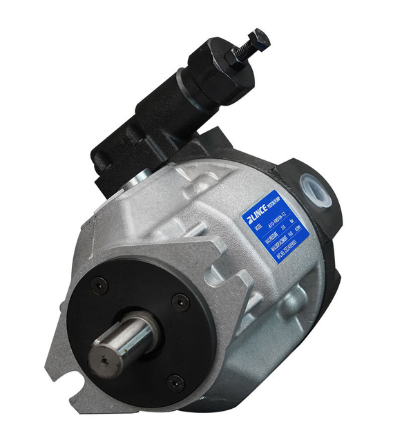
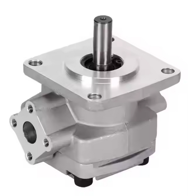
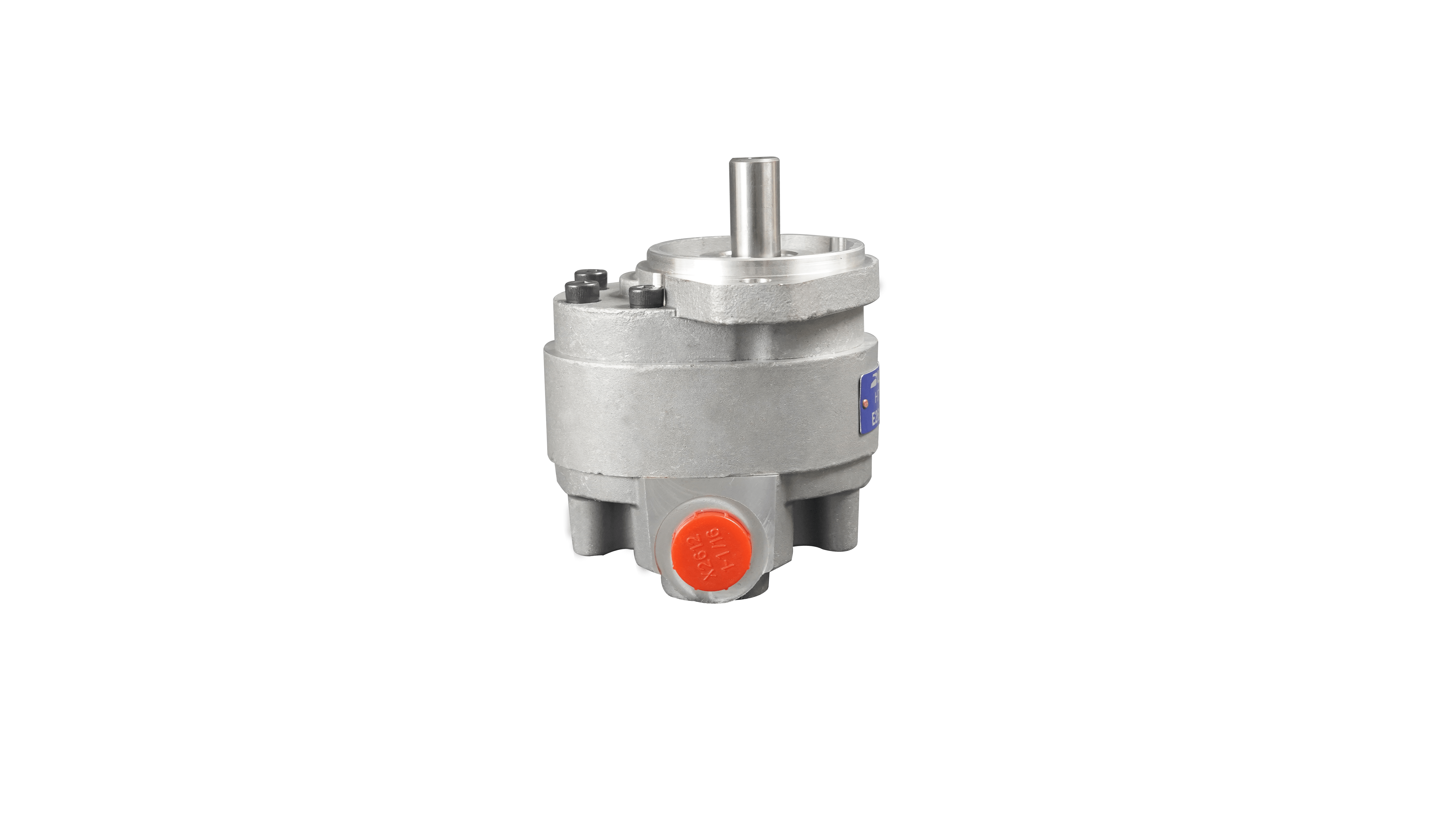
Different designs yield different benchmark percentages under optimal conditions. Gear pumps typically offer lower overall efficiencies due to higher internal clearances. Vane pumps sit in the middle. Piston pumps represent the premium tier, consistently delivering high overall efficiency thanks to their tight tolerances and advanced sealing mechanisms.
Pump Type
Typical Volumetric Efficiency
Typical Mechanical Efficiency
Estimated Overall Efficiency
Common Applications
External Gear
80% - 90%
85% - 90%
75% - 85%
Mobile equipment, lube systems
Vane
85% - 92%
88% - 93%
80% - 90%
Industrial presses, die casting
Axial Piston
92% - 97%
90% - 95%
85% - 95%
Heavy construction, aerospace
Defining Hydraulic System Efficiency (Macro-Level Metrics)
The Pump-Motor Efficiency Double-Whammy (Component Coupling)
Hydraulic motors and actuators possess their own unique efficiency curves. They operate essentially as the mathematical inverse of a pump. When you connect a pump to a motor, their inefficiencies multiply. This compounding loss effect drastically reduces the maximum theoretical efficiency of the circuit before fluid even travels through the hoses.
Consider a scenario where you couple a 90% efficient pump with an 85% efficient hydraulic motor. You multiply 0.90 by 0.85, resulting in a maximum theoretical efficiency of just 76.5%. More than 23% of your input energy is lost strictly to component coupling. This highlights why upgrading just the power generation side often yields disappointing results.
Engineers must evaluate the entire rotary transmission loop. If a high-performance variable displacement pump feeds a worn-out gerotor motor, the system remains fundamentally inefficient. The mechanical output at the motor shaft will never reflect the premium investment made at the pump station.
The Role of Actuators, Valves, and Piping
System efficiency measures the total energy conversion from the electrical or mechanical input at the prime mover down to the final mechanical work at the cylinder or motor. Every component placed between the power source and the load consumes a fraction of that energy. Proportional valves, directional controls, and undersized piping introduce pressure drops that consume energy without performing any useful work.
These efficiency losses directly degrade precision, cycle repeatability, and system control stability in industrial automation. When pressure drops fluctuate due to temperature changes or flow surges, actuators respond inconsistently. A highly efficient system guarantees that the energy put into the fluid is translated directly into predictable, repeatable motion at the actuator.
Manifold blocks often hide significant inefficiencies. Poorly drilled internal passages with sharp 90-degree intersections create massive turbulence. Fluid velocity spikes at these intersections, causing localized heating and pressure degradation. Optimizing manifold design with sweeping internal galleries recovers measurable system efficiency.
Fluid Dynamics and Thermal Losses
Hydraulic energy lost to friction and pressure drops does not simply vanish. It converts directly into heat. Every time fluid is forced through a restrictive fitting or dumped over a relief valve, the system temperature rises. This thermal generation represents pure wasted energy.
Managing this excess heat requires dedicated cooling systems, such as heat exchangers and radiator fans. These cooling circuits require their own power source, further draining energy and degrading overall system efficiency. A hot system is an inefficient system. Paying to cool fluid that was heated by poorly designed circuits is a double penalty on operational budgets.
Thermal imaging cameras provide immediate visual evidence of these losses. Scanning a hydraulic circuit under load quickly identifies restrictive valves or undersized hoses glowing hot on the display. These hot spots pinpoint exactly where mechanical energy is being converted into waste heat.
Prime Mover (Electric Motor/Engine) Impact
The efficiency of the electric motor or diesel engine driving the pump must be factored into the macro-level metrics. An electric motor has its own efficiency rating, typically between 85% and 95%. If the prime mover is inefficient, the entire hydraulic system starts at a disadvantage.
An improperly sized prime mover operating outside its optimal load band will drag down the entire system's efficiency score. Electric motors run most efficiently at 75% to 100% of their rated load. If you install an oversized motor for a low-demand hydraulic circuit, the motor operates inefficiently. It wastes electricity before the mechanical shaft even turns the pump.
The Disconnect: Why a 95% Efficient Hydraulic Pump Doesn't Guarantee a 95% Efficient System
Parasitic Losses and Pressure Drops
Map the journey of hydraulic fluid from the reservoir to the actuator. Along this path, the fluid encounters numerous obstacles that sap its energy. These parasitic losses are the primary reason high-efficiency pumps fail to deliver high-efficiency systems.
Quantifying these losses reveals the true cost of poor plumbing. A single 90-degree fitting can create a pressure drop equivalent to several feet of straight hose. Long hose runs increase fluid friction. Restrictive filtration systems force the pump to work harder just to push fluid through the media. These compounded pressure drops mean the pump must generate 3000 PSI just to deliver 2500 PSI of usable working force at the cylinder.
Field modifications often exacerbate parasitic losses. Maintenance teams might replace a damaged hose with one of a smaller diameter because it was available in the tool crib. That single undersized hose increases fluid velocity, spikes turbulent flow, and introduces a permanent pressure drop into the circuit.
The Impact of Cavitation and Aeration
Poor inlet conditions lead to cavitation. This destructive phenomenon occurs when vapor bubbles form in the fluid and violently collapse against internal pump surfaces. Cavitation not only physically erodes the metal components but drastically reduces the fluid's bulk modulus, or stiffness. Compressible fluid ruins power transmission.
A lower bulk modulus causes sluggish system responsiveness, delayed cycle times, and a sharp drop in volumetric efficiency. The pump wastes energy compressing air bubbles instead of moving fluid. It is necessary to differentiate between pump-induced aeration and system-induced aeration. Pump-induced aeration often stems from suction leaks. System-induced aeration usually results from reservoir design flaws, low fluid levels, or improper baffling returning aerated oil straight to the suction port.
Listening to the equipment provides clues. Cavitation sounds like marbles rattling inside the pump housing. Aeration produces a high-pitched whine. Both conditions destroy efficiency and mandate immediate corrective action regarding inlet plumbing and reservoir fluid dynamics.
Duty Cycles and Load Matching
A major disconnect occurs when there is a mismatch between fixed-displacement pumps and variable system demands. Fixed pumps deliver a constant flow rate regardless of what the actuators require. If the system only needs 50% of the flow, the remaining 50% must go somewhere.
Dumping excess flow over a relief valve during idle or partial-load cycles destroys system efficiency. The pump operates at maximum load, generating massive amounts of heat, while the system performs minimal work. In these scenarios, regardless of the pump's rated performance on a datasheet, the operational efficiency of the machine plummets.
Load-sensing variable displacement pumps solve this mismatch. They adjust their output flow and pressure to match the exact requirements of the actuators in real-time. Upgrading from a fixed gear pump to a load-sensing piston pump eliminates the energy waste associated with dumping fluid over relief valves.
Calculating and Measuring Efficiency in the Field
Formulas for Pump Efficiency
Calculating actual pump efficiency requires specific sensor data gathered during operation. You cannot rely on theoretical numbers if you want accurate field diagnostics. You need to measure input shaft speed, input torque, output flow rate, and the pressure differential across the pump.
Express the calculation in terms of Hydraulic Power Delivered versus Mechanical Power Consumed. Follow these specific steps to calculate the metrics:
Measure the actual flow rate in GPM using an inline turbine flow meter.
Measure the pressure differential in PSI using digital pressure transducers at the inlet and outlet.
Calculate Hydraulic Power (HP) using the formula: (Flow × Pressure) / 1714.
Determine the Mechanical Power input by measuring the electric motor's torque and RPM, using the formula: (Torque × RPM) / 5252.
Divide the Hydraulic Power by the Mechanical Power to find the overall efficiency percentage.
By running these calculations with live data, you isolate the pump's actual performance from the rest of the circuit. This prevents misdiagnosing a healthy pump when the real issue lies in a downstream directional valve.
System-Wide Power Consumption Metrics
To measure system efficiency, you must compare the total input power against the mechanical power exerted by the actuator. For electrically driven systems, use a power meter to measure the actual kilowatts consumed by the electric motor.
Next, calculate the mechanical power output at the cylinder or hydraulic motor. For a cylinder, this is the force exerted multiplied by the distance traveled over time. Divide the mechanical output power by the electrical input power to reveal the true macro-level efficiency of the entire machine. This number is often shockingly low, highlighting the impact of systemic losses.
Tracking these metrics over time establishes a degradation curve. As seals wear, valves bypass, and fluid degrades, the system-wide power consumption will slowly climb to perform the exact same mechanical work. Recognizing this trend allows for proactive maintenance scheduling.
Diagnostic Tools and Baseline Testing
Field measurement requires the right diagnostic equipment. Inline flow meters provide accurate GPM readings under load. Pressure transducers capture rapid pressure spikes and drops better than analog gauges. Power quality analyzers measure the exact electrical draw of the prime mover.
Establishing a performance baseline is mandatory before authorizing any capital expenditure on replacement parts. Record flow, pressure, temperature, and power draw during a standard machine cycle. This baseline allows you to prove whether a subsequent pump upgrade or valve replacement actually delivered the promised efficiency gains.
Portable hydraulic testers combine flow, pressure, and temperature sensors into a single unit. Plumbed directly into the circuit, these testers allow technicians to simulate loads using an integrated needle valve. This verifies pump performance across its entire operating curve without removing it from the machine.
Decision Framework: When to Upgrade the Pump vs. Redesign the System
Evaluating Pump Replacement ROI
Before replacing a component, identify the symptoms that isolate the pump as the primary failure point. Excessive case drain flow is a definitive indicator of internal wear and high slippage. An inability to build pressure at low RPMs also points directly to compromised volumetric efficiency.
Calculate the payback period of upgrading to a high-efficiency variable displacement or load-sensing pump. Compare the initial purchase and installation cost against the projected energy savings. If the current fixed-displacement pump spends 40% of its cycle dumping fluid over a relief valve, upgrading to a load-sensing pump will yield a rapid return on investment.
Review the maintenance logs. If a specific pump requires replacement every six months, upgrading to a heavier-duty model makes sense. However, if the pump fails repeatedly due to cavitation, replacing it with a more efficient model will not solve the underlying inlet restriction.
Identifying System-Level Bottlenecks
When the pump tests within acceptable parameters, shift focus to system-level bottlenecks. A system redesign often yields a higher ROI than replacing the power source. Success criteria for a system redesign include optimizing hose diameters to reduce fluid velocity, upgrading to low-pressure-drop directional valves, and eliminating unnecessary 90-degree fittings.
Implementing accumulator circuits for energy recovery is another powerful redesign strategy. Accumulators store pressurized fluid during idle phases and release it during peak demand. This allows you to downsize the main pump and prime mover. Tuning the system to minimize pressure drops always maximizes the usable energy at the actuator.
Evaluate the filtration strategy. Upgrading from standard cellulose filters to high-efficiency synthetic media reduces pressure drops across the filter housing while providing superior particle retention. This simple system-level change improves fluid cleanliness and reduces parasitic energy loss simultaneously.
Implementation Risks and Mitigation Strategies
Integration Challenges with Existing Infrastructure
Dropping a modern, high-efficiency pump into an aging system carries distinct integration risks. Modern piston pumps react incredibly fast to load changes. This rapid response can introduce structural stress from sudden pressure transients, potentially blowing out old hoses or damaging legacy seals.
Incompatible control interfaces also present challenges. Upgrading to an electronically controlled proportional pump requires integrating new sensors and PLC programming into older relay-logic panels. Ensure the existing infrastructure can handle the speed, pressure, and control requirements of the new component.
Mechanical mounting and shaft alignment require precise execution. High-efficiency pumps often utilize different mounting flanges or shaft splines than legacy gear pumps. Fabricating custom adapter plates or modifying bell housings adds time and complexity to the integration process.
Maintenance and Fluid Conditioning Requirements
High-efficiency components achieve their performance through incredibly tight internal clearances. These tight tolerances make them highly sensitive to fluid contamination. A system that ran fine for years with a rugged gear pump may destroy a new piston pump in weeks if the oil is dirty.
Mitigation requires mandating stricter fluid cleanliness standards, typically targeting specific ISO 4406 codes. Upgrade the filtration system simultaneously with the pump upgrade. Implement regular oil analysis programs to monitor particle counts, water ingress, and additive depletion. Clean, cool fluid is the lifeblood of high-efficiency hydraulics.
Establish a strict breather maintenance protocol. Desiccant breathers prevent airborne moisture and particulate from entering the reservoir as fluid levels fluctuate. Replacing standard vent caps with high-quality desiccant breathers is a low-cost mitigation strategy that protects expensive high-efficiency components.
A hydraulic pump is only as effective as the circuit it powers. High component efficiency is a prerequisite for a high-performance machine, but system efficiency dictates the actual operational energy consumption and cycle times. Upgrading the power source without addressing downstream restrictions is an exercise in futility.
When deciding between a localized pump replacement and a comprehensive system overhaul, rely on data. Replace the pump if diagnostics prove severe internal wear or failure. Overhaul the system if baseline testing reveals chronic energy waste, massive pressure drops, and excessive heat generation.
Take immediate action to optimize your equipment:
Conduct a comprehensive fluid power audit to identify parasitic losses and pressure drops.
Install inline diagnostics, including flow meters and pressure transducers, to establish an accurate performance baseline.
Upgrade filtration systems to meet the strict ISO cleanliness codes required by modern high-efficiency components.
Consult with a hydraulic systems engineer to evaluate accumulator integration and load-sensing upgrades before finalizing procurement.
Conclusion
A hydraulic pump is only as effective as the circuit it powers. High component efficiency is a prerequisite for a high-performance machine, but system efficiency dictates the actual operational energy consumption and cycle times. Upgrading the power source without addressing downstream restrictions is an exercise in futility.
To achieve optimal equilibrium across your entire fluid power architecture, sourcing robust, precision-matched components is paramount. As an industry-leading manufacturer with over two decades of specialized fluid power expertise, BLINCE provides a premium portfolio of high-efficiency orbital motors, piston units, and hydraulic pumps engineered to meet exact operational standards. Our ISO 9001-certified production lines utilize advanced tight-tolerance manufacturing to minimize internal volumetric slip and mechanical drag, giving system designers a highly efficient power source capable of minimizing system-wide thermal generation and maximizing real-world machine output.
When deciding between a localized pump replacement and a comprehensive system overhaul, rely on data. Replace the pump if diagnostics prove severe internal wear or failure. Overhaul the system if baseline testing reveals chronic energy waste, massive pressure drops, and excessive heat generation. Take immediate action to optimize your equipment:
Conduct a comprehensive fluid power audit to identify parasitic losses and pressure drops.
Install inline diagnostics, including flow meters and pressure transducers, to establish an accurate performance baseline.
Upgrade filtration systems to meet the strict ISO cleanliness codes required by modern high-efficiency components.
Consult with a hydraulic systems engineer to evaluate accumulator integration and load-sensing upgrades before finalizing procurement.
FAQ
Q: What is a good overall efficiency rating for a hydraulic pump?
A: Overall efficiency ratings vary by design. Piston pumps typically offer the highest efficiency, ranging from 85% to 95%. Vane pumps generally fall between 80% and 90%, while gear pumps usually operate at 75% to 85% efficiency, depending on operating pressures and fluid conditions.
Q: How does fluid viscosity affect hydraulic pump efficiency?
A: Fluid viscosity heavily influences volumetric and mechanical efficiency. If the fluid is too thin, internal leakage increases, dropping volumetric efficiency. If the fluid is too thick, mechanical friction increases, and the pump may suffer from cavitation due to inlet starvation.
Q: Why does my system run hot even with a new pump?
A: Heat is a byproduct of system inefficiency, not just pump wear. If your system runs hot with a new pump, you likely have severe pressure drops, undersized hoses, or a fixed-displacement setup dumping excess flow over a relief valve. The energy lost to these restrictions converts directly into heat.
Q: Can I improve system efficiency without replacing the pump?
A: Yes. You can significantly improve system efficiency by increasing hose diameters to reduce fluid velocity, replacing restrictive 90-degree fittings with sweeping bends, upgrading to low-pressure-drop valves, and ensuring the fluid is properly cooled and filtered.
Q: What is the difference between volumetric and mechanical efficiency?
A: Volumetric efficiency measures fluid flow, specifically the ratio of actual flow delivered versus theoretical flow capacity. Mechanical efficiency measures energy consumption, comparing the theoretical torque required to turn the pump against the actual torque needed to overcome internal friction.
This article is a general engineering guide. Final component selection should be based on machine drawings, measured hydraulic data, working conditions, safety requirements, and confirmation from a qualified hydraulic engineer or supplier.
Blince Hydraulic Team
Blince Hydraulic is an industry-leading company dedicated to precision-engineered fluid power manufacturing and custom hydraulic solutions. Backed by decades of deep field expertise in industrial machinery and thousands of successful global deployments, our engineering team focuses entirely on high-performance hydraulic component manufacturing, including specialized orbital motors, high-pressure travel drives motor, and robust directional control valves. Our production infrastructure utilizes state-of-the-art multi-axis CNC machining systems and is fully ISO 9001 certified to guarantee repeatable volumetric accuracy across every single manufacturing run.
We deliver fast, highly dependable, and cost-efficient hydraulic solutions to heavy industry distributors, machinery OEMs, and maintenance crews across more than 150 countries. Whether your active project calls for a small-volume batch of customized shaft profiles or a large-scale production run of severe-duty cast iron gear pump, we configure our flexible production schedules to meet your target lead times with total pricing predictability. Partnering with Blince means securing maximum system efficiency, elite material quality, and uncompromised fluid power professionalism.
To learn more about our complete product lineup, visit our official website: www.blince.com.