Unexpected hydraulic pump failure carries severe operational and financial penalties. When a system goes down on a job site or industrial plant floor, the cost of lost production often dwarfs the price of the replacement component. Premature failure usually points to a systemic application mismatch rather than an inherent product defect. Understanding the factors that degrade performance keeps operations running smoothly and prevents catastrophic downtime.
There is a stark discrepancy between idealized manufacturer lifespan ratings and real-world industrial applications. While some sources cite a 10 to 20-year lifespan, pumps in demanding environments frequently fail in under 10,000 hours. In harsh duty cycles involving medium-pressure piston pumps, failures can occur in as little as 1.5 years. Recognizing this gap is the first step toward better maintenance strategies.
To accurately predict service life, operators must evaluate operating parameters, pump architecture, and fluid dynamics. This evaluation helps in making informed repair-versus-replace decisions and specifying the correct replacement unit. By understanding what affects the lifespan of a Hydraulic Pump, maintenance teams can implement strategies to maximize uptime and reduce overall expenses.
Lifespan is Conditional: A hydraulic pump's life expectancy is not a fixed chronological guarantee; it is a calculation based on operating hours, pressure loads, and speed limits.
Contamination is the Primary Threat: Up to 80% of premature hydraulic pump failures are driven by fluid contamination, making filtration as critical as the pump selection itself.
The Max-Load Penalty: Operating a pump simultaneously at maximum rated pressure and maximum rated speed exponentially degrades bearing life, sometimes reducing service life to under 1,500 hours.
Strategic Replacement: Choosing between rebuilding an existing unit and upgrading to a different pump type requires an operational analysis factoring in downtime, efficiency losses, and maintenance intervals.
Table of Contents
Toggle
Baseline Life Expectancy: How Long Should a Hydraulic Pump Last?
Chronological Years vs. Operating Hours
Measuring lifespan in chronological years is misleading without defining the duty cycle. A pump sitting idle for months will naturally last longer in years than one running 24/7 in a steel mill or on a heavy excavator. Operating hours provide a much more accurate metric for evaluation. Industry standards typically benchmark expected life between 10,000 and 20,000 hours, depending on the application and maintenance rigor. When you track hours, you align maintenance schedules with actual mechanical wear rather than arbitrary calendar dates.
Consider a unit operating on a plastic injection molding machine running three shifts. That machine logs roughly 6,000 hours a year. A 10,000-hour pump will barely last 20 months in this scenario. Conversely, a unit on a log splitter used seasonally might take 30 years to hit 10,000 hours. Tracking hours via machine telematics or simple hour meters is the only reliable way to gauge remaining life.
The B10 Bearing Life Standard
Manufacturers use the L10 or B10 bearing life calculation to predict service life. This standard estimates the point at which 10% of bearings in a given population will fail under specific loads and speeds. Because bearings are the foundational internal components supporting the rotating group, their expected survival rate serves as a baseline for predicting the overall life of the pump. If the bearings fail, catastrophic pump failure follows closely.
The B10 calculation assumes proper lubrication and alignment. It factors in radial and axial loads applied to the shaft. When you increase system pressure, you increase the load on these bearings, which drops the B10 life exponentially. Understanding this mathematical relationship helps engineers specify units with adequate bearing capacity for the intended duty cycle.
Manufacturer Ratings vs. Real-World Duty Cycles
Laboratory test conditions rarely match field realities. Manufacturers test pumps using clean fluid, steady states, and moderate temperatures. In contrast, real-world applications involve shock loads, temperature spikes, and variable fluid quality. This gap explains why field performance often falls short of catalog ratings. Operators must account for these environmental stressors when estimating how long a unit will actually survive in their specific system.
Shock loads are particularly damaging. A sudden spike in pressure, common in stamping presses or mobile equipment hitting an obstruction, sends a shockwave through the fluid directly into the pump internals. These spikes often exceed the relief valve reaction time, forcing the pump to absorb the mechanical stress. Over time, these repeated micro-traumas fatigue the metal components, leading to premature failure well before the catalog rating suggests.
How Pump Architecture Dictates Service Life
External and Internal Gear Pumps
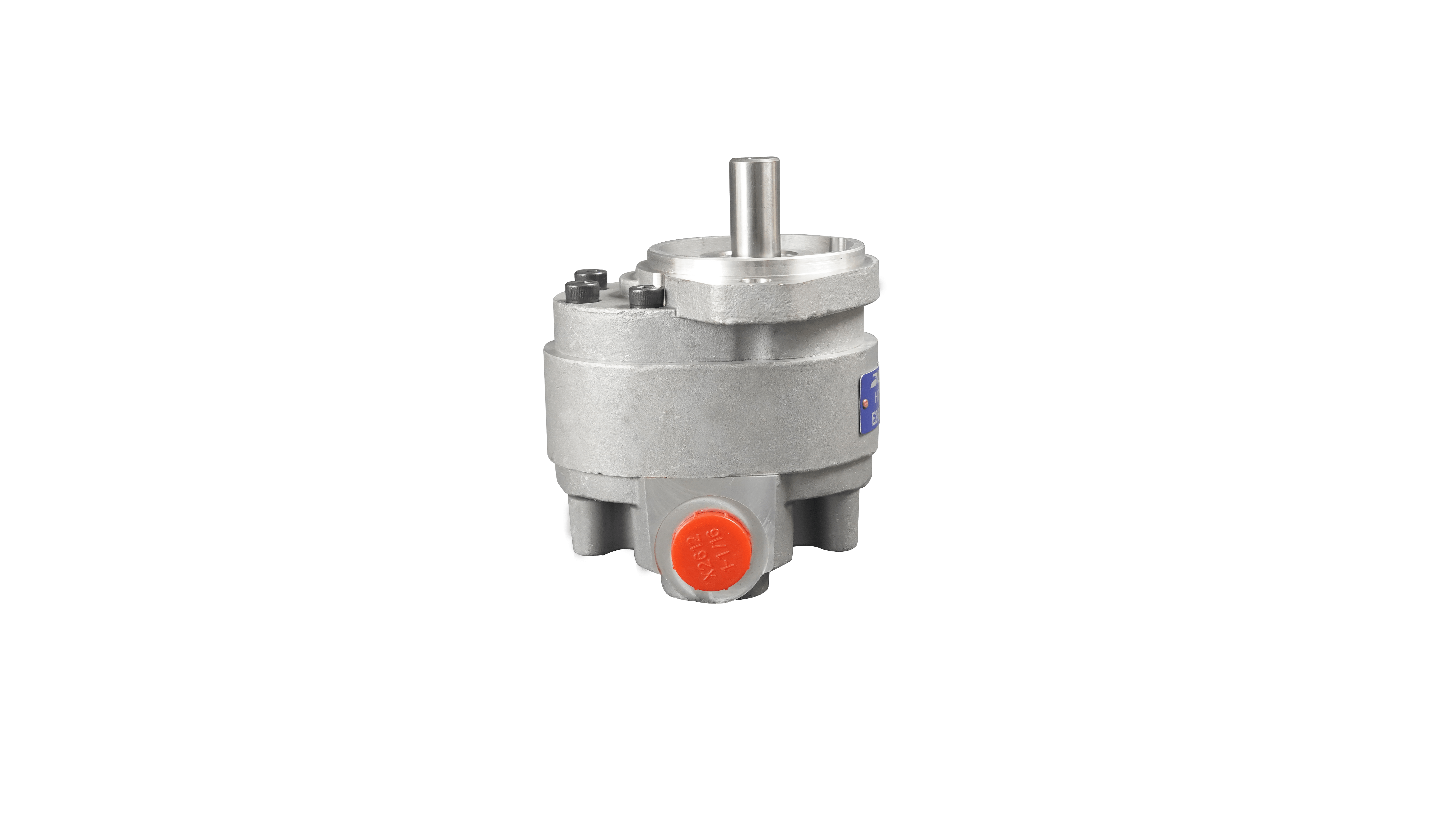
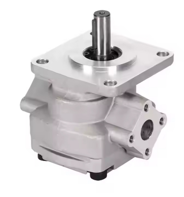
Gear pumps are known for their robust construction and high tolerance for contamination. They handle less-than-ideal fluid conditions better than more complex designs. Wear over time increases internal clearances between the gears and the housing. This wear leads to a gradual loss of volumetric efficiency rather than sudden, catastrophic mechanical failure. Operators will notice a drop in flow rate and increased heat generation as the pump ages.
Because gear pumps have fewer moving parts and rely on hydrodynamic films to separate the gear journals from the bushings, they are highly reliable in dirty environments like agriculture and mining. However, once the housing is scored by debris, the internal leakage (slip) increases. You cannot easily repair a worn gear pump housing; replacement is usually the only practical option once efficiency drops below acceptable levels.
Vane Pumps
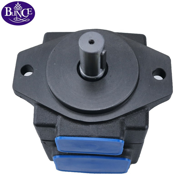
Vane pumps offer excellent efficiency and low noise levels. The primary wear point is the contact between the vanes and the cam ring. A major maintenance advantage of vane pumps is the ability to replace internal cartridges. This modular design allows technicians to effectively reset the pump's service life without replacing the entire housing, saving both time and component costs during overhauls.
The vanes rely on centrifugal force and system pressure to maintain contact with the cam ring. If the fluid is contaminated, the vanes can stick in their rotor slots. When a vane sticks, it fails to sweep the fluid, causing a sudden drop in flow and severe localized wear on the cam ring. Regular fluid monitoring is necessary to prevent varnish buildup that causes vane sticking.
Piston Pumps (Axial and Radial)
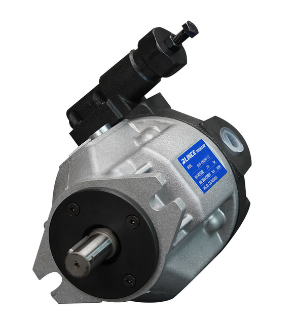
Piston pumps handle high-pressure, continuous-duty applications with ease. They offer long theoretical bearing life when operated within specified limits. Their complex internal tolerances make them highly vulnerable to fluid contamination. Abrasive particles can quickly score the pistons, slipper pads, and valve plates. Catastrophic failure in a piston pump is often expensive due to the precision required in its manufacturing and repair.
Axial piston pumps, like the PVP 33 series, use a swashplate to drive the pistons. The clearance between the piston and the cylinder barrel is often less than a thousandth of an inch. Even microscopic silt can bridge this gap, causing scoring and rapid efficiency loss. Maintaining strict ISO cleanliness codes is non-negotiable when operating piston equipment.
Primary Factors That Degrade Hydraulic Pump Life
Fluid Contamination and Particulate Wear
Fluid contamination drives the majority of premature failures. Abrasive particles score internal surfaces, degrading efficiency and generating secondary wear particles. This creates a destructive cycle that rapidly accelerates wear. Water contamination also poses a severe threat. It reduces fluid lubricity, promotes rust, and accelerates bearing fatigue, drastically shortening the operational life of the unit.
Particulate contamination is categorized by size in microns. Particles in the 3 to 10-micron range are the most damaging because they are the exact size of the dynamic clearances within the pump. They act like lapping compound, grinding away metal surfaces. Implementing proper breather filters on reservoirs and using high-efficiency return line filters are standard practices to combat this issue.
Common Contaminants and Their Effects
Contaminant Type
Source
Impact on Pump Life
Silica (Dirt/Dust)
Breather vents, cylinder rod seals
Abrasive wear on valve plates and gear housings.
Wear Metals
Internal component degradation
Accelerates secondary wear; acts as a catalyst for fluid oxidation.
Water
Condensation, heat exchangers
Destroys fluid film thickness; causes rust and cavitation.
Air
Suction line leaks, low reservoir levels
Causes aeration, spongy operation, and localized overheating.
Operating Pressure and Speed Extremes
Pushing equipment to its absolute limits degrades life exponentially. Operating a unit simultaneously at maximum rated pressure and maximum rated speed severely penalizes bearing life. Design data for certain piston-type units indicates that running at these dual maximums can slash expected life to approximately 1,440 hours. Operators should aim to run systems below maximum ratings to ensure longevity.
When designing a circuit, engineers typically size the pump so it operates at 70% to 80% of its maximum continuous pressure rating. This safety margin absorbs pressure spikes and reduces the mechanical strain on the shaft and bearings. Running at 100% capacity leaves no room for error and guarantees a short service life.
Fluid Temperature and Viscosity Breakdown
Excessive heat destroys the lubricating properties of hydraulic fluid. High temperatures thin the fluid, breaking down the critical lubricating film between moving parts. This thinning accelerates metal-to-metal contact and increases internal wear. Excessive heat bakes and degrades elastomeric seals, leading to external leaks and allowing air or contaminants to enter the system.
Hydraulic systems should generally operate between 110°F and 130°F. Once fluid temperatures exceed 140°F, the life of the oil is cut in half for every 18-degree increase. This thermal degradation creates sludge and varnish, which stick to internal components and restrict flow. Installing adequate heat exchangers and ensuring the reservoir has proper airflow are necessary steps to manage temperature.
Cavitation and Aeration
Cavitation occurs when fluid cannot completely fill the pump inlet, causing vapor bubbles to form and violently collapse under pressure. This collapse physically erodes internal metal surfaces, causing pitting. Aeration happens when air enters the fluid, often through leaks in the suction line. Both phenomena create excessive noise, reduce efficiency, and drastically shorten the operational life of the internal components.
You can usually identify cavitation by a distinct rattling sound, often described as marbles passing through the pump. It is typically caused by a clogged suction strainer, cold fluid with high viscosity, or an undersized inlet line. Fixing cavitation requires immediate attention to the suction side of the circuit to restore proper fluid flow.
Evaluating Replacement vs. Repair: A Decision Framework
Assessing Overall Operational Costs
Evaluating whether to repair or replace requires looking beyond the initial purchase price. Operators must calculate the cumulative costs of downtime, lost production, and repeated repairs of an aging unit. A new pump might have a higher upfront cost, but improved efficiency and reliability often yield a better return on investment over time compared to nursing a failing unit.
When a pump loses volumetric efficiency, it takes longer to perform the same amount of work. A cylinder that used to extend in 5 seconds might take 8 seconds. Over a shift, those lost seconds add up to significant production losses. Replacing a worn unit restores cycle times and reduces the energy wasted as heat through internal leakage.
When to Rebuild vs. When to Replace
Rebuilding makes sense for minor seal leaks or when accessible cartridge replacements are available. It is a cost-effective way to extend service life for certain designs. Total replacement is necessary in cases of catastrophic housing damage, severe bearing failure, or when dealing with obsolete models where parts are scarce. Extensive internal scoring usually dictates a complete replacement.
Inspect the housing for deep scoring or cracks. If found, replace the unit.
Check the shaft for twisting or spline wear. A damaged shaft often indicates severe internal binding.
Evaluate the cost of parts and labor. If the rebuild cost exceeds 60% of a new unit, replacement is generally the smarter choice.
Consider lead times. Sometimes a new unit is available off the shelf, while rebuild parts take weeks to arrive.
Upgrading Pump Specifications
Premature failure often indicates that the original unit was undersized for the application. If a pump fails repeatedly, operators should evaluate the system demands. Upgrading to a higher-displacement model or switching from a gear design to a piston design might be necessary for demanding applications. Ensuring the component matches the actual duty cycle prevents recurring failures.
If you upgrade displacement, you must also verify that the electric motor or diesel engine has enough horsepower to drive the larger pump at the required pressure. You also need to check that the existing relief valves and directional control valves can handle the increased flow without creating excessive pressure drops.
Implementation Risks and Life Extension Strategies
Filtration and Fluid Conditioning Upgrades
Installing a new unit without addressing fluid quality guarantees a repeat failure. High-efficiency filtration is a mandatory risk mitigation strategy. Upgrading to tighter micron ratings or adding offline kidney-loop filtration ensures the fluid remains clean. Proper fluid conditioning protects the tight tolerances of modern components and significantly extends their operational life.
A kidney-loop system operates independently of the main hydraulic circuit. It pulls fluid from the reservoir, passes it through a high-efficiency filter and a heat exchanger, and returns it to the tank. This continuous polishing removes micro-particles and water, maintaining fluid cleanliness even when the main machine is shut down.
Implementing Predictive Maintenance
Routine oil analysis tracks ISO cleanliness codes and wear metals, providing early warning signs of internal degradation. Vibration analysis helps detect bearing wear before catastrophic failure occurs. Predicting remaining useful life remains challenging because durable equipment often lacks full life-cycle run-to-failure data. Localized testing and establishing baseline models are essential for effective predictive maintenance.
Taking fluid samples correctly is vital. Always pull samples from a dynamic zone, such as a return line, while the system is operating at normal temperature. Samples taken from the bottom of the reservoir will show artificially high contamination levels due to settled sludge. Consistent sampling intervals allow you to trend the data and spot sudden spikes in wear metals like copper or iron.
System Redesign Considerations
Before commissioning a replacement, evaluate the entire hydraulic circuit. Verify that the reservoir size allows for adequate fluid cooling and de-aeration. Check inlet lines for restrictions to prevent cavitation. Ensure the system has adequate cooling capacity to maintain optimal fluid viscosity. Addressing these system-level factors prevents the new component from suffering the same fate as the old one.
Reservoirs should ideally hold three to five times the pump's per-minute flow rate. This volume gives the fluid time to rest, allowing air bubbles to rise to the surface and heavy contaminants to settle to the bottom. If space constraints force the use of a smaller reservoir, you must compensate with aggressive cooling and advanced baffling techniques.
Conclusion
A hydraulic pump's life expectancy reflects its operating environment, fluid quality, and adherence to design parameters rather than a guaranteed timeframe. Understanding the specific duty cycle is necessary for realistic lifespan expectations. Proper maintenance and system design dictate how long the equipment will survive in the field.
To bridge the gap between theoretical durability and extreme real-world duty cycles, sourcing high-durability components is essential. As an industry-leading manufacturer with over two decades of fluid power expertise, BLINCE delivers a comprehensive selection of high-performance orbital motors, piston units, and hydraulic pumps designed to resist extreme system stressors. Our ISO 9001-certified production lines employ stringent quality controls and microscopic manufacturing tolerances to combat premature wear and internal leakage, ensuring your fluid power networks maintain peak performance throughout an extended service life.
When specifying a new unit, match the architecture to the required duty cycle. Ensure operating parameters fall comfortably below maximum ratings to avoid the max-load penalty. Prioritize contamination control to protect internal components from abrasive wear. Next steps:
Conduct a comprehensive fluid analysis to establish a baseline for contamination and wear metals.
Audit your system's operating pressures and speeds to ensure they remain below the manufacturer's maximum continuous ratings.
Install high-efficiency return line filters or a kidney-loop system to maintain strict ISO cleanliness codes.
Consult with a fluid power engineer to verify that your current pump architecture is properly sized for your actual production demands.
FAQ
Q: What is the average lifespan of a hydraulic pump in hours?
A: The industry standard benchmark is typically between 10,000 and 20,000 operating hours. This varies heavily based on the pump type, operating pressures, fluid cleanliness, and maintenance practices. Harsh environments can reduce this significantly.
Q: How does operating pressure affect hydraulic pump life?
A: Increased pressure exponentially increases bearing load, reducing L10 life. Operating a piston pump simultaneously at maximum pressure and maximum speed can reduce its lifespan to roughly 1,440 hours due to extreme mechanical stress.
Q: What is the most common cause of premature hydraulic pump failure?
A: Fluid contamination is the leading cause. Abrasive particles score internal surfaces, causing particulate wear, which degrades volumetric efficiency and rapidly destroys internal components like valve plates and gear housings.
Q: Can a hydraulic pump actually last 20 years?
A: Yes, but typically only in low-duty, highly maintained, and perfectly clean environments. Such ideal conditions are rare in heavy industrial applications where shock loads and continuous operation are the norm.
Q: How do you calculate the remaining useful life of a hydraulic pump?
A: Predictive methods include vibration analysis, volumetric efficiency testing, and fluid wear-metal analysis. Because full life-cycle historical data is often lacking, benchmarking against the pump's initial clean state is necessary to track degradation.
Q: Is it better to rebuild or replace a failing hydraulic pump?
A: Rebuild if damage is limited to seals or replaceable cartridges. Replace if there is severe housing damage, catastrophic bearing failure, or if the application requires upgrading to a more robust design to handle increased loads.