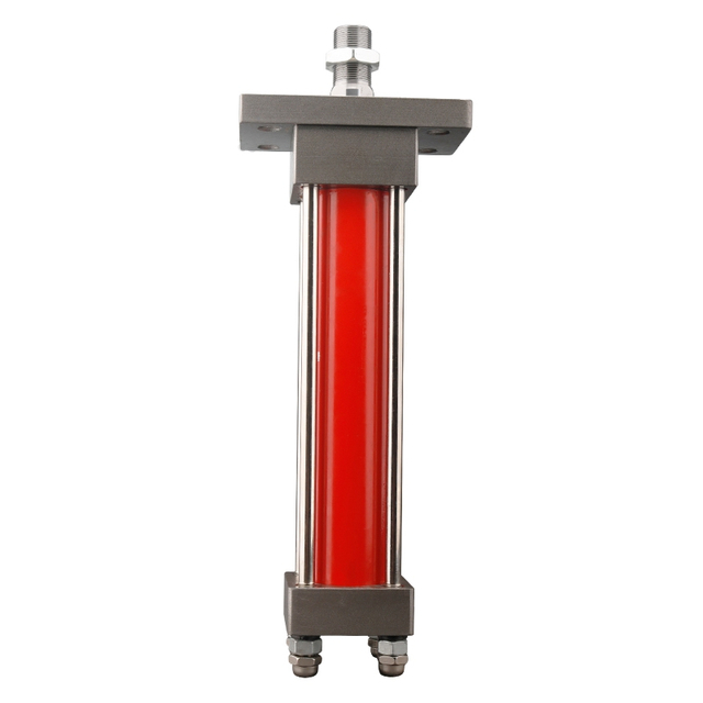
Two cylinders can each run acceptably from a test power unit and still behave badly when connected to one machine. Start them together and one may move first. Retract them together and the return line may carry more oil than the pump sends out. Hold one cylinder while moving the other and the control circuit has to preserve the held position without sending unused pump flow across a relief valve for the entire dwell. These are different duties, even if the cylinders have the same maximum pressure on their drawings.
Yes, one unit can feed both. The drawing must show whether A and B ever ask for oil together. In the example below, that decision changes the extension flow from 15.08 to 24.43 L/min. It still leaves the valve designer to deal with a rod running ahead or a parked cylinder drifting. A suspended or personnel-supporting load requires the machine's approved load-control design and qualified review.
BLINCE lists a custom power unit, not one fixed set of ratings. Its page gives no pump curve for the cycle in this article. That curve and the offered unit's schematic, motor data and drawing have to come with the proposal.
Put both cylinders on one time line
Draw A and B as two bars over the same cycle. In the example below, B's extension ends at 6 seconds; A keeps going for 2 more. That first six-second interval is the pump-flow problem. The slow working stroke may instead set pressure. During a hold, neither cylinder moves, yet a fixed pump left circulating at high pressure can still heat the oil. The time line makes those three different duties visible.
The sketch needs the stroke distance or speed, load and duration beside each moving bar. Mark the event that starts the next motion: operator input, PLC command, limit switch or pressure signal. If an operator can press both controls, the overlap belongs in the sizing case. “Normally one at a time” is useful only when the actual controls enforce it.
Machine state
Flow question
Pressure and control question
Data that can change the selection
A extends, B parked
A cap-end inlet flow
Is B held against a load while A moves?
A bore, stroke, target time; B load and holding method
A and B extend together
Sum of simultaneous cap-end inlet flows
Which branch requires the higher local pressure, and how is flow divided?
Both speed targets and loaded branch readings
A holds, B moves
B inlet flow, plus any designed leakage or pilot flow
Is A isolated, counterbalanced or controlled by another approved method?
Hold duration, allowable drift, load direction, schematic
Both retract
Sum of annulus inlet flows; separately sum cap-end exhaust flows
Can either load drive a cylinder faster than commanded?
Rod diameters, retract times, return-path ratings
Dwell or idle
Pump delivery may still circulate, unload or destroke
Where does energy go while neither actuator does work?
Time in state, pump control and valve neutral condition
The table also exposes what a workshop test can miss. A clamp may hold cold and drift warm; a cylinder may slow only when the second branch opens. If an external load can drive either cylinder, its holding method needs qualified review.
The BLINCE Hydraulic System category currently routes to the custom power-unit product. Use the exact product page as the commercial destination, then supply the sequence above so the inquiry can be matched to a design. The category and product listing do not replace a circuit drawing.
Calculate oil volume and flow at each cylinder port
For a double-acting cylinder, the cap-end area is the full bore area. The rod-end effective area is the bore area less the rod area. In metric units:
A_cap (mm²) = π × bore⊃2; / 4
A_annulus (mm²) = π × (bore⊃2; − rod⊃2;) / 4
V_stroke (L) = area (mm²) × stroke (mm) / 1,000,000
Q_required (L/min) = V_stroke (L) × 60 / motion time (s)
The rod occupies part of the piston area on the return side. Hence the same stroke takes more oil through the cap port than through the rod port. Use cap area for extension inlet flow and annulus area for retraction inlet flow. A regenerative circuit needs a different calculation.
Oil power follows P (kW) = pressure (bar) × flow (L/min) / 600. Use pressure and flow from the same point in the same state. The electric input will be higher; the proposed pump and motor curves, at the intended oil temperature, determine how much higher.
For extension force, pressure on the rod side pushes back. With pressures taken at the cylinder ports, the ideal piston calculation is F_ext = p_cap × A_cap − p_rod × A_annulus. If the rod port is near zero pressure, the cap-side term gives a quick upper estimate. The tool can still see less force after seal friction and linkage losses.
The area and flow equations follow Parker's mobile cylinder application guide. The machine's cylinder drawings, rather than this example, supply the dimensions and ratings for an order.
Worked example: the overlap changes the first pump screen
Take two ordinary double-acting cylinders, both hypothetical. A is 80 mm bore, 45 mm rod and 400 mm stroke; its loaded extension should take 8 seconds at an assumed 120 bar at the cylinder, and its return 6 seconds. B is 63/36 × 300 mm, with a 6-second extension at an assumed local 90 bar and a 5-second return. No BLINCE configuration or customer test produced these figures. They leave out acceleration, cushioning, leakage and line loss.
A's cap end takes 2.011 L for its 400 mm stroke. Eight seconds therefore calls for 15.08 L/min at that port. On return, 1.374 L enters the smaller annulus in 6 seconds, or 13.74 L/min. The cap port exhausts more; that return flow is checked below.
B takes 0.935 L at the cap port on extension, equivalent to 9.35 L/min over 6 seconds. Its rod port takes 0.630 L on the 5-second return, or 7.56 L/min. These are geometric flows; a purchase calculation uses the actual cylinder drawing.
The timing choice changes the quote. Run A then B under an enforced sequence and the larger extension flow is A's 15.08 L/min, spread over 14 seconds of travel. Start them together and the first six seconds need 15.08 + 9.35 = 24.43 L/min. B stops while A finishes. A 20 L/min unit can look adequate on two separate worksheets yet miss the machine's simultaneous target.
At the assumed 120 bar common supply, 24.43 L/min represents 4.89 kW of oil power. That is the overlap state to show on the motor-duty chart.
The offered pump curve must show its delivered flow under load; a displacement on a nameplate cannot confirm either the single-stroke or overlap speed.
The 4.89 kW figure is not a motor rating. The proposed pump and motor data need to cover a loaded start, the six-second overlap and the expected starts per hour at the site's ambient temperature.
A common pump cannot synchronize travel by itself
“Both cylinders move together” could mean simultaneous commands with different finish times, or matched position throughout travel. Specify which behavior the machine needs. A plain tee from one pump cannot assure matched position: oil in parallel branches divides according to their changing resistance. The easier-moving cylinder may start first or take more flow. HAWE's parallel-circuit explanation describes that starting behavior.
At six seconds, B stops; A has two seconds left. The schematic must show where B's flow goes then. A's speed in those last two seconds depends on that valve state.
If “together” means matched position, the permissible error needs a number in millimeters and a load condition. Otherwise there is no way to judge a divider, metered branch, linkage or feedback system. The choice also has to cover startup and the moment one side reaches its stop; unequal loads and internal leakage can change the error before then.
Equal division would send about 12.22 L/min to each branch. A needs more and B less for their stated times, so equal flow would miss both targets.
The return side can be the governing flow path
During double-acting retraction, oil enters the smaller annulus while the full cap-end volume leaves. Thus cap-end exhaust flow can exceed pump inlet flow to the rod side. In the example, A receives 13.74 L/min at its annulus for a 6-second return, while about 2.011 × 60 / 6 = 20.11 L/min leaves its cap end. B receives 7.56 L/min at its annulus during a 5-second return while approximately 0.935 × 60 / 5 = 11.22 L/min leaves its cap end.
During the common 5 seconds of retract, the pump sends 21.30 L/min into the two rod ends while 31.33 L/min leaves the cap ends. A then returns alone for its final second. The numbers are at the cylinder ports; a filter or cooler sees their sum only if both branches join upstream of it. Trace the actual return route on the proposed schematic before using either figure to select a shared component.
A return line restricted below the actual peak can raise backpressure, slow motion, add heat and alter the pressure available for the work stroke. The correct check is the selected component's pressure drop at the peak flow, oil viscosity and temperature, together with its pressure rating. A nominal hose diameter, filter element code or cooler port size alone does not tell you the loss. The BLINCE oil-cooler sizing guide expands that heat and pressure-drop decision when a cooler is part of the return path.
Both rods fully extended leave about 0.94 L less oil in the reservoir than at the start (A: 0.636 L; B: 0.305 L). That is a low-level check, not a tank capacity.
The peak return is a separate tank event: the two cap ports can expel 31.33 L/min for five seconds on retract. Where that oil enters, how it crosses the baffles and whether it carries air matter even though the net level swing is small. Bosch Rexroth's power-unit design paper includes return and decompression peaks in reservoir design.
Pressure belongs to a state and a measurement point
For the example, “A needs 120 bar” has to mean something precise: ideally, the pressure difference needed at A's ports during the loaded part of extension. If 120 bar was instead measured only at the pump outlet, the cylinder may have less available pressure after line and valve losses. If the rod side has material backpressure, the ideal extension-force calculation using 120 bar on the cap alone overstates useful force. A local loaded reading and return reading are more informative than a relief setting copied from a nameplate.
At the assumed port pressures, ideal cap-side force is 60.3 kN for A and 28.1 kN for B. Return pressure, friction and linkage reduce force at the tool; the two figures cannot simply be added into a platform rating.
The BLINCE pressure-gauge placement guide shows why test-point location changes the interpretation. Label each reading with its port and machine state. Live testing and adjustment still follow the machine manual and a qualified procedure.
Holding one cylinder while the other moves
While B advances, A may be clamping a part or supporting a vertical load. Drift that merely spoils a clamp operation can become a safety hazard under a suspended load. The machine's load-control design must cover power and hose failure; a centered directional valve by itself is insufficient evidence.
For a quote, give A's hold time, allowable drift and load direction. Also say what happens after power loss and on restart. Keeping the pump at pressure, recharging periodically and resting the load on a mechanical support lead to different circuits; the machine designer must verify the selected holding method.
During hold, fixed-pump flow sent across a high-pressure relief becomes heat. The circuit should show whether the pump unloads, stops or bypasses while A remains held; Bosch Rexroth discusses this tradeoff in its power-unit paper.
If the proposed answer is “switch the motor off during dwell,” check pressure decay and restart under load. If it keeps running, identify the bypass path and pressure for the whole hold period. The relief setting and holding devices serve protective functions; changing them is not a substitute for understanding the dwell state.
A duty chart decides drive and thermal checks
The example gives a six-second peak but no dwell time or cycles per hour. It cannot yet support a thermal rating. A time/load chart fills that gap by showing when the pump runs, unloads or stops. HAWE's compact power-pack documentation uses this kind of function and duty diagram; its published equipment limits do not apply to the BLINCE build.
Cycle count alone hides motor run time. The inquiry needs the duration of motion, hold and idle, plus whether the motor starts against pressure. State the available AC supply or the DC battery voltage under load and cable conditions; the BLINCE AC/DC guide covers that choice.
The proposed schematic should identify throttling between the 120 and 90 bar branches and any high-pressure bypass during hold. Those paths, with their durations, give a basis for estimating heat. Cooler capacity and pressure drop then have to be checked at the actual oil flow and hottest expected cooling condition.
Choose the control route after the motion requirement is clear
An enforced A-then-B cycle may suit one fixed pump with separately controlled branches. Sustained overlap at different branch pressures can change that choice, as can a long pressurized dwell. Compare the candidate circuits against the measured duty and the holding requirement; the table lists the evidence each option needs.
Required behavior
Initial architecture question
Main cost or limitation to examine
Evidence before a quote
Strictly sequential, short intermittent moves
Can one pump and two controlled branches meet the largest single state?
Longer total cycle; interlock and hold logic must be reliable
Timed sequence, maximum state flow/pressure, hold requirement
Two independent functions may overlap
Can the pump and drive supply the permitted combined flow at the governing pressure?
Larger drive and return path; branch interaction and heat
Overlap timing and loaded pressure at each branch
Equal position under unequal loads
What sensing or balancing method meets the position tolerance?
Added valves, controls, tuning, diagnostics and failure modes
Should the pump unload, stop, vary displacement or vary speed?
Added controls or components versus operating heat and energy
Time/load chart, starts per hour, temperature and supply
Load can overrun or descend
What approved load-control and emergency behavior are required?
Circuit complexity and possible pressure loss
Machine risk assessment and exact load path
The table is a starting point for the supplier discussion. For this six-second overlap, ask whether the proposed pump and valves can deliver both speeds under load. If the buyer also expects synchronized position, the allowable error belongs on the drawing. A safety-critical load requires the machine's approved design and qualified review.
For a replacement, include the old schematic and nameplates. A tank of the same outside size and a matching pressure number say nothing about valve ports, neutral flow, wiring or cooling. If production speed increased before the old unit failed, send the earlier and current cycle times. Buying the same nominal size could reproduce the overload.
What to measure on an existing machine
Suppose A reaches its target time alone but slows when B starts. Time the separate moves and the permitted overlap at similar oil temperatures, noting each gauge location. A change only during overlap points the investigation toward shared flow or branch control. A change only after warm-up calls for the same pressure and flow readings hot and cold.
If pump pressure looks normal while A stalls, a permitted test point after the valve or coupling may expose the missing pressure. Record motor current, supply voltage and oil pressure together during overlap. Foam on combined retract calls for an inspection of level, suction and the return entry.
Keep each flow, pressure and current reading with its stroke time, oil temperature and test point. A cold no-load flow reading paired with a hot loaded pressure reading gives a false power estimate. Work near moving or suspended loads follows the machine's approved test procedure; the supplier can begin with drawings and symptoms if measurements must wait.
If the schematic is missing, trace the pump, valves, cylinder ports and return on a marked sketch. Add relief, pilot and case lines where present. Have the machine designer confirm that sketch before a replacement is released.
A short RFQ that preserves the engineering decisions
The BLINCE custom power-unit page is a place to send a configuration inquiry. For the hypothetical machine in this article, a first note could read as follows. The bracketed items are deliberately left for the buyer; they cannot be inferred from cylinder dimensions.
We need one unit for [machine]. A is 80/45 × 400 mm (8 s extend, 6 s return); B is 63/36 × 300 mm (6 s extend, 5 s return). They may extend together. Our measured port pressures and loads are [values and test points].
In a separate state, A must hold [load] while B moves for [time], with no more than [drift]. Our supply is [AC voltage/phase/frequency or DC battery conditions]. The machine runs [cycles per hour], with [run time] and [dwell time] per cycle. Ambient and oil temperatures are [range].
Attached are [schematic or marked sketch] and [nameplate and connection photos]. Please show the delivered flow during overlap, the return route and A's holding method. We also need the connection drawing and proposed acceptance test.
The supplier's response should address the 24.43 L/min extension overlap and show whether a shared component sees the 31.33 L/min cap-end return. A quotation based only on “two cylinders, 200 bar” misses both.
Questions left after the first calculation
Can one power unit run two cylinders with different bores?
Yes. Different bores change the oil each stroke needs; the branch controls determine how the available flow is divided.
Should pump flow equal the sum of both cylinder flows?
Only during overlap. Here, A then B calls for 15.08 L/min at most on extension; starting both together calls for 24.43 L/min for six seconds. An operator override counts as overlap unless the controls prevent it.
Should the two cylinder pressures be added?
No. A common supply has to reach the branch that needs more pressure after line and valve losses. Feeding the lower-pressure branch can incur a loss of its own. Two separate pump sections would need a different power calculation.
Why is combined return flow sometimes higher than pump flow?
The rod makes the inlet side smaller than the exhausting cap side. In this example, the cap ports expel 31.33 L/min while the pump feeds 21.30 L/min into the rod ports.
Does a bigger tank solve overheating?
More oil slows the temperature rise. It does not remove the heat created by sustained relief bypass; that flow path and the cooling capacity need checking.
Is a tee enough to synchronize two cylinders?
No. With different loads, one branch can take more oil. A no-load demonstration says little about loaded travel. Give the allowable position error so a circuit designer can assess the control method.
What if the machine has a vertical or suspended load?
Give the machine designer the load direction, permitted drift and required behavior on power or hose failure. A neutral directional valve or retained pump pressure cannot stand in for the approved load-control design.
What should BLINCE confirm before an order?
The offered unit needs a pump curve, motor data, valve schematic, return-path and cooling basis, connection drawing and agreed test conditions. Those belong to the actual proposed configuration; the public listing has no fixed rating to substitute for them.
Sources behind the sizing method
The cylinder equations come from the relationships in Parker's application guide. HAWE supports the function and time/load diagrams and the behavior of parallel branches; Bosch Rexroth addresses return peaks and fixed-pump bypass losses. Those sources support the method used here. The proposed BLINCE unit still needs its own component data and approved machine schematic.
This article is a general engineering guide. Final component selection should be based on machine drawings, measured hydraulic data, working conditions, safety requirements, and confirmation from a qualified hydraulic engineer or supplier.
Blince Hydraulic Team
Blince Hydraulic is an industry-leading company dedicated to precision-engineered fluid power manufacturing and custom hydraulic solutions. Backed by decades of deep field expertise in industrial machinery and thousands of successful global deployments, our engineering team focuses entirely on high-performance hydraulic component manufacturing, including specialized orbital motors, high-pressure travel drives motor, and robust directional control valves. Our production infrastructure utilizes state-of-the-art multi-axis CNC machining systems and is fully ISO 9001 certified to guarantee repeatable volumetric accuracy across every single manufacturing run.
We deliver fast, highly dependable, and cost-efficient hydraulic solutions to heavy industry distributors, machinery OEMs, and maintenance crews across more than 150 countries. Whether your active project calls for a small-volume batch of customized shaft profiles or a large-scale production run of severe-duty cast iron gear pump, we configure our flexible production schedules to meet your target lead times with total pricing predictability. Partnering with Blince means securing maximum system efficiency, elite material quality, and uncompromised fluid power professionalism.
To learn more about our complete product lineup, visit our official website: www.blince.com.