The electric motor starts cleanly. The pump sounds normal. A pressure gauge rises to the number written on the work order. Yet the cylinder needs twice as long as expected to complete its stroke.
That combination starts an argument in many workshops. One person wants a larger pump. Another wants a higher relief setting. Someone else blames the cylinder because the machine moved correctly during the empty test. All three ideas can be expensive when nobody has measured how much useful flow reaches the actuator under load.
Purchase requests for an electric hydraulic pump often arrive with three numbers: voltage, maximum pressure, and tank capacity. Those figures identify part of the package, but they say little about speed or endurance. I have seen 5.5 kW assemblies fitted with very different pump displacements. I have also seen a compact pack complete a ten-second lift without complaint, then become too hot to touch when the next job required twenty minutes of motor operation. Even the apparently simple choice between 12 V and 24 V depends on the battery, cable run, contactor, valve arrangement, and how often the unit starts.
Start at the moving part. Work out the oil volume needed for one stroke or one motor revolution, then check the pressure while the real load is present. That gives the useful hydraulic demand. The motor has to cover the losses as well. So do the rest of the parts: a small valve passage, a dirty filter, or a narrow return hose can spoil an otherwise sensible motor-and-pump choice.
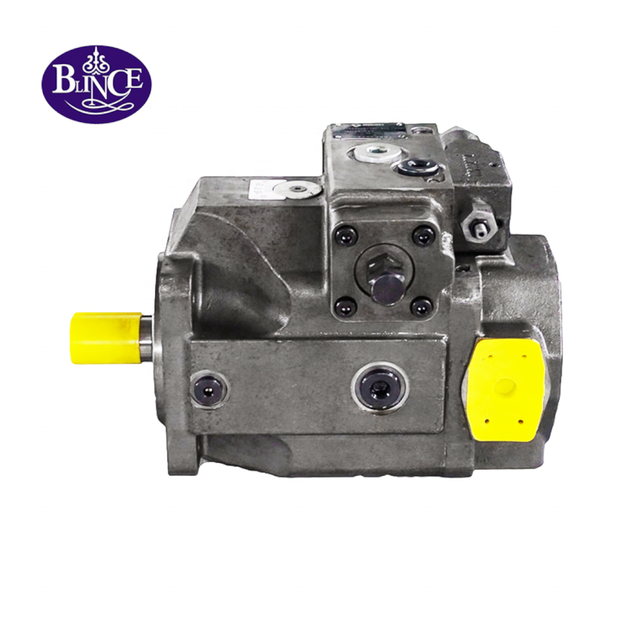
BLINCE offers a custom hydraulic power unit that combines the reservoir, electric motor, pump, and valve functions around the application. The public product page describes a configurable platform rather than one universal specification. That is the right way to view an electric power unit: configuration follows the machine data.
The Short Answer
For a first selection, calculate actuator flow and take a pressure reading during the troublesome part of the cycle. Convert those two values into hydraulic power. Only then choose AC or DC, motor size, pump displacement, tank, valve block, filtration, cooling, ports, and controls. All of those choices should describe the same cycle, not separate catalog maxima.
These equations are screening tools. The pump will deliver less than its geometric calculation once leakage is included, and the motor will draw more input power than the oil receives. A cold start, a loaded restart, several relief events, or frequent cycling can expose that margin quickly. Use the selected pump curve and motor data before treating the result as a product size.
Do not submit only “230 V, 200 bar, 20 L tank” or “24 V electric over hydraulic pump.” Send the actuator dimensions, load, required speed, normal and peak pressure, cycle timing, simultaneous functions, voltage and phase, start-under-load condition, control sequence, oil, ambient range, mounting space, line sizes, and the behavior that caused the replacement.
Why “Electric Hydraulic Pump” Is Broader Than a 12 V Power Pack
The phrase is deliberately broad. At one end is a small battery-powered pack that raises a tail lift a few times per hour. At the other is an AC station that runs a press or test stand through an entire shift. Between them are gear-pump clamp units, quieter vane-pump packages, and piston-pump systems with unloading, cooling, filtration, and more involved controls.
Voltage tells you how the motor is fed; it does not tell you which hydraulic pump belongs behind it. The BLINCE hydraulic pump range includes several pump types, while a complete power unit adds the tank and control hardware. A buyer still has to reconcile working pressure, useful flow, noise, oil cleanliness, control response, and service life.
Official application forms show the same logic. Bucher Hydraulics asks for flow, operating pressure, relief setting, time on, time off, fluid, cylinder data, start-under-load behavior, ambient temperature, voltage, current, power, phase, frequency, enclosure, mounting, and ports in its AC/DC hydraulic power-pack application sheet. Those fields are not paperwork for its own sake. Each one can change the motor, pump, tank, valve, or thermal decision.
Start With the Machine Cycle, Not the Motor Nameplate
Before choosing a unit, describe what the machine does from the first command until it is ready to repeat the cycle.
Does one cylinder extend while another holds pressure? Does a hydraulic motor run continuously or only index a shaft for three seconds? Must the unit start against trapped pressure? Does the machine cycle six times per hour or six times per minute? Will the pump unload between movements, stop completely, or remain on pressure while the operator loads the next part?
A workshop note does not need polished language. It needs useful facts:
Double-acting clamp cylinder: 100 mm bore, 50 mm rod, 600 mm stroke. Extension takes 20 seconds; retraction takes 15. Pressure stays near 180 bar for about 12 seconds, followed by 45 seconds unloaded. The machine makes eight cycles per hour on one shift. Supply is 400 V, 50 Hz, three phase. After two hours the oil reaches 72°C. Return pressure climbs when fixture two retracts.
Now the supplier knows when the heat appears and which movement raises return pressure. “Quote a 5.5 kW pump” hides both clues.
When a slow machine still shows normal pressure, note where the gauge is fitted. The hydraulic pressure gauge placement guide explains why this matters. A gauge beside the pump cannot report a loss farther downstream unless a second test point is used.
What an Electric Hydraulic Power Unit Actually Contains
Open a basic power unit and the main pieces are easy to recognize: electric motor, motor-pump connection, pump, tank, suction pickup, relief valve, and outlet ports. The rest varies with the job. One unit may have only a hand valve and gauge; another may carry filters, a cooler, pressure switches, an accumulator, a PLC interface, or an emergency-lowering circuit.
The motor converts electrical input into shaft power. The pump converts shaft rotation into oil flow. Pressure develops when the load and circuit resist that flow. The valve determines where the flow goes. The reservoir stores and conditions the oil. Every stage can limit useful actuator performance.
That variation is why a pump swap can leave the original complaint untouched. Put a nominal 30 L/min pump ahead of a small valve passage and the extra delivery appears as pressure loss, not useful speed. If slow motion or heat started after valve work, compare the neutral and work-port functions with the hydraulic directional control valve selection guide.
Calculate Actuator Flow Before Choosing Pump Displacement
For a double-acting cylinder, cap-end piston area is:
A piston = π × D⊃2; / 4
Rod-side annular area is:
A annular = π × (D⊃2; - d⊃2;) / 4
where D is cylinder bore and d is rod diameter.
Oil volume for a stroke is area multiplied by stroke. With millimetre dimensions:
V (L) = area (mm2) × stroke (mm) / 1,000,000
Required theoretical flow is:
Q (L/min) = V (L) × 60 / movement time (s)
Worked AC Example: 100 mm Bore, 600 mm Stroke
Use the clamp cylinder from the field note: 100 mm bore, 50 mm rod, 600 mm stroke. The arithmetic below is a sizing check. It is not a BLINCE model recommendation.
Cap-end area:
A piston = π × 100⊃2; / 4 = approximately 7,854 mm2
Cap-end oil volume:
V cap = 7,854 × 600 / 1,000,000 = approximately 4.71 L
Both answers happen to be 14.14 L/min because the requested times were chosen to match the two oil volumes. Change either time and they separate. With equal pump flow, this cylinder would ordinarily retract faster than it extends.
Suppose the pump delivers 88 percent of its geometric flow and the loaded motor speed is close to 1,450 rpm. The displacement needed to screen 14.14 L/min is:
This leaves an 11.1 cm3/rev starting point. Before placing an order, check the actual speed and the maker's flow curve at the intended pressure and oil viscosity. Inlet condition and duty may rule out a pump that looks correct on displacement alone.
Convert Flow and Pressure Into Motor Power
At 180 bar and 14.14 L/min:
P hydraulic = 180 × 14.14 / 600 = approximately 4.24 kW
Assume 82 percent overall efficiency for preliminary screening:
P electrical input = 4.24 / 0.82 = approximately 5.17 kW
The 5.17 kW result sits uncomfortably close to a 5.5 kW nameplate. It may work, or it may leave too little margin once the pump starts against pressure or the room warms up. Check starting torque, service factor, starts per hour, relief time, enclosure, and the actual supply. Sometimes the better correction is an unloading arrangement rather than the next larger motor.
Do not use the synchronous speed printed in a catalog as measured shaft speed. A four-pole motor on 50 Hz usually turns below 1,500 rpm once loaded, and the same pole count changes speed on 60 Hz. A VFD adds adjustment, but low-speed motor cooling and pump inlet filling still set limits. So does the pump's maximum permitted speed.
The hydraulic pump and motor matching guide explains the shared relationship among flow, pressure differential, speed, torque, and oil temperature. Those variables remain linked when the prime mover is electric.
AC or DC Electric Hydraulic Pump?
AC and DC units solve different installation problems. Neither is universally stronger or more efficient.
Selection point
AC electric hydraulic power unit
DC electric hydraulic power unit
Typical supply
120/230 V single phase or 230/400/460 V three phase, depending on region and motor
12, 24, 36, or 48 V battery system, depending on equipment
Typical duty
Better suited to repeated or longer industrial operation when correctly rated and cooled
Common for short intermittent mobile cycles and equipment without mains power
Current level
Lower current at higher voltage for a given input power
Very high current can occur at 12 or 24 V
Starting
Contactors, starters, overload protection, soft starters, or VFDs may be used
Battery condition, contactor, cable, ground, and voltage sag are critical
Installation
Requires appropriate mains supply, protection, earthing, and enclosure
Requires battery capacity, charging strategy, short heavy conductors, and DC-rated switching
Main advantage
Practical for factory equipment and sustained operation
Compact mobile power where an engine-driven pump or mains supply is unavailable
Main disadvantage
Less portable; supply compatibility and electrical installation matter
Heat and voltage drop can limit repeated high-power operation
Choose AC when the machine has a stable mains supply and the cycle demands repeated or longer operation. Three-phase motors are often practical for industrial power units because starting and continuous operation can be handled without the extreme conductor current of low-voltage DC.
Choose DC when mobility, compactness, and short operation matter more than continuous output. Tail lifts, small tippers, service vehicles, emergency functions, and compact mobile attachments are common examples. The exact motor data must approve the current and on-time; “intermittent duty” is not permission to repeat a ten-second run without limit.
A DC Example Shows Why Voltage Matters
Now consider a smaller mobile job: an 80 mm bore, 500 mm stroke single-acting cylinder, 15 seconds up, about 160 bar while loaded.
The cylinder takes about 2.51 L for the stroke. Moving that volume in 15 seconds calls for roughly 10.05 L/min before leakage.
Hydraulic power:
P hydraulic = 160 × 10.05 / 600 = approximately 2.68 kW
At a simplified 75 percent overall efficiency:
P input = 2.68 / 0.75 = approximately 3.57 kW
Idealized current at 12 V:
I = 3570 / 12 = approximately 298 A
Idealized current at 24 V:
I = 3570 / 24 = approximately 149 A
The figures above are idealized. A real DC motor may pull substantially more at breakaway or near stall. This is why a long undersized cable can present itself as a hydraulic fault: voltage reaches the battery, but not the motor under load.
Take two voltage readings during the same loaded lift, one at the battery posts and one at the motor terminals. The gap belongs to the cables, lugs, contactor, isolator, and ground return. A resting value of 12.7 V is reassuring but incomplete; it says nothing about the drop when current approaches 200 or 300 A.
Fixed-Displacement or Variable-Displacement Pump?
A fixed-displacement gear pump is often the straightforward choice for a lift, clamp, transfer unit, or intermittent mobile pack. Delivery rises roughly with shaft speed. That simplicity has a consequence: while the shaft turns, oil keeps coming. The circuit must stop the motor or provide a deliberate unloading or bypass path when the actuator stops.
Where noise matters, a vane pump may be worth considering, though poor inlet conditions and dirty oil are less forgiving. A piston pump brings higher-pressure and control options. It also brings a case drain, tighter cleanliness expectations, and more limits to check before commissioning.
A variable pump can reduce delivery during the quiet part of a cycle instead of wasting full flow across a valve. That can be useful on a machine with changing demand. It is not a free upgrade for every compact unit. If the added controls, standby behavior, commissioning work, and maintenance do not solve a real operating problem, the simpler fixed pump may be the sounder purchase.
Pump approach
Useful strengths
Real limitations
Typical fit
Fixed-displacement gear pump
Compact, economical, simple, broad service familiarity
Delivers whenever it turns; throttling or relief loss can create heat
Simple cylinders, intermittent power packs, basic machine functions
Vane pump
Smooth delivery and often quieter operation
Sensitive to inlet condition, oil cleanliness, viscosity, and application limits
Industrial units where noise and steady flow matter
Variable piston pump
High pressure and flexible pressure/flow control
Higher cost and greater control, case-drain, cleanliness, and commissioning demands
Multi-function or energy-conscious industrial systems with variable demand
Do not buy a more complex pump merely because it appears more capable. The correct choice is the least complex architecture that meets the actual pressure, flow, duty, control, efficiency, noise, and life requirements.
Duty Cycle Is a Thermal Limit, Not a Marketing Label
An electric hydraulic pump can pass a five-second functional test and fail after an hour of production. The missing variable is often duty.
Write down a full hour of operation. Note each start, how long the motor runs loaded, how long it idles or holds pressure, and the time available to cool. Add ambient and oil temperature. Ten seconds on and ten minutes off is an easy life compared with ten seconds on every half minute, even though both may be called “intermittent.”
Compact-unit documentation makes this explicit. Bucher’s UP40 catalog describes a mobile power pack for short operations at middle-to-high pressure and warns that pressure values and cycle count must be considered before selection. Its application sheet separately asks for time on and time off because one percentage cannot describe every thermal pattern.
On an AC unit, read the duty designation together with starts per hour, enclosure, cooling method, service factor, and room temperature. For DC, the useful document is the motor's current-versus-on-time curve and the required cooling interval. Frame size and voltage are poor substitutes.
If oil temperature keeps rising, read the hydraulic oil cooler sizing guide before ordering a larger cooler. A cooler removes heat; it does not correct continuous relief flow, excessive throttling, a blocked return, an overloaded motor, or a pump that never unloads.
Start Under Load Changes the Electrical Decision
Listen to the first half-second of startup. A motor that begins with the pump open to tank has a much easier job than one that meets trapped pressure immediately. Check valves, counterbalance valves, pilot checks, an accumulator, a loaded cylinder, or the spool center can all leave the next start loaded.
A star-delta starter, soft starter, or VFD changes how an AC motor accelerates. None of them creates missing torque or cures a pump that is being run outside its inlet or speed limits. Select the starter with the motor, supply, and actual starting pressure in view.
Low speed and high shaft torque are the worst electrical moment for a DC motor. If it labors, measure battery and motor-terminal voltage during the same valve command. Long leads, warm contactors, weak grounds, and repeated hot starts often explain why the hydraulic side appears weak.
Reservoir Size: Usable Oil, Air Release, and Heat
There is no tank multiplier that settles every design. On a tipper, the first question may be whether enough oil remains above the suction pickup at full extension. On a factory station, air release, heat, settling, and access may dominate instead. Use the installed angle and the entire actuator cycle when marking minimum and maximum levels.
A single-acting cylinder may take most of the usable oil out of a small tank during one stroke. A continuously running station has a different concern: oil returning hot and aerated needs time and space before reaching the pump again. Extra volume can help, but it also means more oil to buy, more mass to heat, and a larger installation footprint.
The hydraulic tank breather selection guide is useful because reservoir oil level changes move air through the breather. A blocked breather can create tank vacuum and pump inlet trouble; an open vent can invite moisture and dirt.
Do not mount the reservoir in a way that uncovers the suction pickup during vehicle tilt or cylinder return. Do not treat nominal tank volume as usable volume. Check minimum and maximum oil levels through the complete cycle and at the expected mounting angle.
Return Flow Can Exceed Pump Flow
Return flow is easy to underestimate on a double-acting cylinder. In the earlier example, the full-bore area is about 7,854 mm2, while the rod-side annular area is only about 5,890 mm2.
If the pump supplies 14.14 L/min to the rod side during retraction, cap-end return flow is approximately:
So a 14.14 L/min pump can send nearly 18.9 L/min through the return hardware during retraction. A valve or filter selected from pump flow alone may be the restriction that only appears in that direction.
The hydraulic tubing and hose selection guide explains why pressure, flow, velocity, temperature, movement, routing, and fittings belong in the same line decision. A hose can have the correct pressure rating and still have an internal passage or bend arrangement that wastes pressure.
Valve Logic Decides What Happens in Neutral
The pump and motor can be correctly sized while the machine still behaves incorrectly because neutral valve logic is wrong.
An open-center circuit may unload fixed pump flow to tank when no function is active. A closed-center circuit blocks flow and normally belongs with a pump or unloading strategy designed for it. A tandem center can unload the pump while blocking work ports. Motor spools, float positions, load checks, and pilot-operated valves add other behaviors.
Describe the neutral behavior in plain language. Should the cylinder stay put, lower under control, float, or retract? Should the motor stop hard, coast, or receive make-up oil while an overhauling load drives it? Two valves with the same port count and coil voltage can answer those questions differently.
BLINCE’s hydraulic valve category covers directional, flow, solenoid, overcenter, and pressure-control functions. The appropriate product family follows the circuit requirement; it should not be guessed from the old coil or outside body shape.
Filtration and Cleanliness Protect the New Unit
A failed pump does not keep its debris to itself. Metal and elastomer can remain in the tank bottom, manifold passages, hoses, cooler, bypass path, or actuator. Installing the replacement into that circuit gives the old failure a second chance.
Use the failure evidence to decide how far the cleanup must go. The hydraulic contamination control guide covers the wider oil path. At minimum, inspect the filter and tank; after a destructive failure, include trapped lines and cavities rather than assuming a fresh drum of oil completes the repair.
Filter selection must consider required cleanliness, flow, cold-oil pressure drop, bypass setting, collapse rating, indicator, and location. Installing a finer element without checking differential pressure can starve the pump or send oil through bypass during cold start.
Pressure Loss Is Lost Power
Every restriction between pump and actuator consumes part of the available pressure. Every unnecessary restriction in the return path raises actuator outlet pressure and reduces usable pressure differential.
Heat created by pressure loss can be screened with:
Power loss (kW) = pressure drop (bar) × flow (L/min) / 600
If a valve and fitting group drops 15 bar at 20 L/min:
Power loss = 15 × 20 / 600 = 0.50 kW
That small-looking 15 bar loss is half a kilowatt of continuous heating at 20 L/min. A larger motor may keep the actuator moving, but the loss remains. Put gauges on both sides of the suspected part and repeat the same load at the same oil temperature.
Quick couplers deserve attention on mobile or frequently disconnected circuits. The outside thread can match while the internal passage, valve style, or partial engagement creates an unexpected loss. The hydraulic quick-coupler pressure-drop guide is useful when a new attachment runs slower or hotter than the base machine.
Cooling Should Follow a Heat Balance
Oil temperature is the result of heat generated minus heat rejected. Reservoir surface, steel structure, airflow, cooler performance, ambient temperature, duty, and hydraulic loss all contribute.
Before buying a cooler, find out where the heat is made. Hold a hand-held temperature probe or pressure gauges across the suspected section during the complaint. Relief flow, throttling, a filter in bypass, high case pressure, or a fixed pump held against pressure can produce heat faster than a cooler can hide it.
For an air-oil cooler, look at the air path before the catalog rating: blocked fins, slow fan speed, and hot-air recirculation are common field limits. A water-oil unit depends on the available water temperature, flow, and quality. Once the heat load and installation space are known, compare those conditions with the BLINCE hydraulic heat-exchange category.
Controls, Sensors, and Electrical Protection
The hydraulic package does not end at the coil leads. Write down what the machine must do after a power cut, emergency stop, broken sensor wire, or spool that fails to return. That decision determines how the pressure switch, relay, PLC output, proportional valve, and emergency circuit should interact.
At quotation stage, send the supply voltage, phase, frequency, full-load current, starting method, enclosure, grounding, coil voltage, and connector details. Electrical protection and machine safety still have to be validated at system level; selecting the hydraulic components does not complete that assessment.
Do not use the relief valve as the machine’s only safety device. Do not assume a directional valve securely holds a suspended load. The selected machine may require counterbalance valves, pilot-operated checks, mechanical props, guards, monitored controls, or redundant measures based on its risk assessment.
Equipment-Specific Checks
Industrial Presses and Clamping Fixtures
Industrial fixtures often need rapid approach, controlled working speed, pressure holding, and fast return. A two-stage circuit, unloading valve, accumulator, or variable pump may reduce installed power compared with sizing one constant flow for the worst point of the entire cycle.
For a clamp, say whether pressure must remain after the motor stops. Then watch how often the unit restarts. A three-second run every few seconds can create more heat than one longer movement followed by a real cooling pause. Seal leakage, valve leakage, accumulator condition, and pressure-switch reset should be checked before motor size is blamed.
Lift Tables, Tail Lifts, and Mobile Platforms
These applications may use compact DC power packs and gravity lowering. Check cylinder volume, loaded raise time, battery recovery, cable path, lowering control, emergency descent, hose-burst protection, and mechanical support for service.
Do not assume the load itself guarantees smooth lowering. Oil viscosity, valve metering, geometry, side load, and an empty platform can change descent behavior. A no-load jog verifies direction; it does not approve the loaded machine.
Machine Tools and Test Stands
A test stand may spend nearly all day below its maximum pressure. What the operator notices instead is noise, temperature drift, dirty oil, or a pressure value that will not repeat. In that setting, an AC station with proper filtration and unloading usually deserves more attention than the smallest possible power pack.
Record the complete operating sequence. A test stand that spends most of its time at low flow but occasionally needs high flow may justify variable speed, a variable pump, or staged pumps. The best answer depends on the duty profile and control accuracy.
Agricultural and Construction Equipment
Mobile equipment adds problems that are absent in a clean plant room. A tractor may sit through winter, then work long days around fertilizer and dust; a loader sees vibration, wash-down water, and steep angles. Inspect cable support and connectors alongside the breather, suction hose, oil grade, and cooler face.
If the base machine behaves normally with every attachment except one, do not condemn the power unit first. Compare that attachment's motor displacement, couplers, case drain, return route, and running time. The new tool may simply ask for a different flow path than the machine was built to provide.
Who Should Not Buy a Compact Electric Hydraulic Power Pack
A compact DC pack is a poor starting point for a continuously driven hydraulic motor unless its current curve, cooling, battery supply, and stated duty specifically cover the job.
Do not buy from voltage, maximum pressure, and tank size alone when cylinder or motor flow has not been calculated. Those labels can all match while the machine remains slow.
Replacing a PTO or engine-driven pump with an electric unit is not a simple change of prime mover. Calculate the continuous hydraulic power first. The required motor, battery or mains supply, charger, and cooling package may be much larger than the existing installation suggests.
Do not order a fixed-displacement pump for a closed-center or continuously pressurized circuit without an unloading or control strategy. The unit can waste power and overheat while the actuator is idle.
An off-the-shelf power pack is also the wrong purchase when the machine needs hazardous-area approval, certified safety functions, marine protection, special-fluid seals, or food-contact materials. Those requirements belong in the specification and documentation before a unit is built.
Practical Checklist Before Ordering
Information to send
Why it changes selection
Machine function and full cycle sequence
Shows when flow, pressure, holding, unloading, and reversing are required
Cylinder bore, rod, stroke, quantity, and movement time
Determines oil volume, flow, force, and return-flow ratio
Hydraulic motor displacement, target rpm, torque, and case drain
Determines motor flow, pressure differential, return, and cooling needs
Normal pressure, peak pressure, and relief setting
Separates working load from protection setting and sets power demand
AC/DC voltage, phase, frequency, and available supply
Determines motor and electrical architecture
Start under load, starts per hour, time on, and time off
Controls starting torque and thermal duty
Simultaneous functions and priority requirements
Prevents adding every maximum flow or missing combined demand
Pump type, displacement, speed, and rotation
Establishes delivery, compatibility, and inlet demand
Valve schematic and neutral behavior
Determines unloading, holding, reversing, and heat generation
Reservoir usable volume and mounting orientation
Protects suction, oil expansion, air release, and cycle volume
Hose, tube, fittings, couplers, filter, cooler, and return data
Exposes restrictions and excessive velocity or back pressure
Oil type, viscosity, operating temperature, and contamination history
Changes leakage, inlet filling, lubrication, filtration, and cooling
Ambient range, water/dust exposure, and installation envelope
Determines enclosure, cooling, layout, and component protection
Photos, nameplates, schematic, port details, and failure story
Reduces assumptions and distinguishes replacement from redesign
If several items are unknown, selection can begin, but the result should be marked preliminary. A quotation based on incomplete machine data is an estimate, not proof of compatibility.
Common Buying and Installation Mistakes
Mistake 1: Choosing From Maximum Pressure
Maximum pressure is a survival limit, not a flow or power rating. Use realistic working pressure with required flow and duty.
Mistake 2: Ordering Motor Kilowatts Before Calculating Flow
Motor power is a consequence of pressure, flow, efficiency, and duty. The same motor can drive very different pump displacements and machine speeds.
Mistake 3: Treating AC and DC as Interchangeable
AC and DC units need different motors, switching, protection, and supply architecture. Voltage conversion affects every coil and control component, not only the pump motor.
Mistake 4: Sizing Return Lines From Pump Flow Alone
Cylinder area ratio can make return flow exceed pump delivery. Measure or calculate the worst direction.
Mistake 5: Ignoring Start-Under-Load Pressure
A motor that starts easily with an unloaded pump may trip, stall, or draw excessive current against trapped pressure.
Mistake 6: Using Relief Adjustment to Correct Slow Speed
Relief pressure does not create flow. A higher setting can add current, stress, and heat when the real restriction remains.
Mistake 7: Reusing Dirty Oil After Pump Failure
Metal and elastomer debris can remain in the tank, filter, cooler, valves, hoses, and actuators. A clean-looking new unit can be damaged by the previous failure path.
Mistake 8: Treating the Reservoir as a Container Only
Usable oil volume, pickup depth, air release, expansion, cooling, return placement, and maintenance access all matter.
Mistake 9: Testing Cold and Unloaded Only
A cold, unloaded jog confirms rotation and basic movement. It does not reproduce hot leakage, battery sag, repeated starts, or a return restriction that appears only under load.
Mistake 10: Choosing a Larger Pump Without Checking the Circuit
More displacement raises potential flow and shaft torque demand. The motor, inlet, valve, filter, cooler, hoses, fittings, and return must carry the change.
A Quote Request That Gives Engineering Something to Work With
Instead of writing “Quote one 5.5 kW electric hydraulic pump, 200 bar,” send a technical note:
Clamp unit for one double-acting cylinder: 100 mm bore, 50 mm rod, 600 mm stroke. Loaded extension is 20 seconds and retraction is 15. Working pressure is close to 180 bar; the clamp remains at pressure for 12 seconds. The unit runs eight cycles per hour on an eight-hour shift. Supply: 400 V, 50 Hz, three phase. After two hours the existing ISO VG 46 oil reaches 72°C. Return pressure rises when the second fixture retracts. Nominal tank volume is 40 L and the available space is 900 × 500 × 650 mm. Attached are the schematic, pump and motor plates, valve-block and cooler photos, port dimensions, filter information, and loaded pressure readings.
That request lets the supplier challenge the proposed 5.5 kW assumption. The answer may be a different motor, pump displacement, unloading method, reservoir, valve passage, return line, cooler, or cycle arrangement.
For a DC mobile unit, also send battery voltage and capacity, charging method, positive and ground cable lengths, conductor size, contactor information, voltage at the motor under load, maximum current if measured, and the required number of consecutive cycles.
FAQ
What is an electric hydraulic pump?
It is a hydraulic pump driven by an electric motor rather than an engine or PTO. Many buyers actually need the complete power unit, which adds the reservoir, relief and directional valves, filters, ports, and electrical controls around the motor-pump group.
How do I size an electric hydraulic pump?
First calculate how much oil the actuator must move and how quickly. Measure pressure during the loaded part of that movement. The calculation bar × L/min / 600 gives hydraulic kilowatts; after that, allow for motor and pump losses and check the actual speed, starting condition, duty, valve capacity, return flow, tank, and cooling.
Is an AC or DC hydraulic power unit better?
AC is usually easier to sustain on factory equipment with a stable mains supply. DC earns its place on mobile or emergency equipment where the machine has a battery and only needs short runs. The better option is the one whose supply and duty match the real cycle.
What motor size is required for 180 bar at 14 L/min?
The oil receives about 180 × 14 / 600 = 4.2 kW. At an assumed 82 percent overall efficiency, the electrical input is roughly 5.1 kW. That is too close to a catalog boundary to approve a motor by arithmetic alone; starting pressure, service factor, ambient temperature, and the selected pump curve still have to be checked.
How is hydraulic pump displacement calculated?
For a fixed pump, divide required flow by loaded shaft speed and allow for volumetric loss: flow × 1000 / (rpm × volumetric efficiency). Using 14.14 L/min, 1,450 rpm, and 0.88 gives a screening value close to 11.1 cm3/rev.
Does increasing motor power make a cylinder faster?
Not necessarily. Cylinder speed follows useful flow and piston area. A larger motor only helps when a different pump can use the extra shaft power and the inlet, valves, lines, and return side can carry the added flow.
Why does an electric hydraulic pump run hot?
Start by noting when the temperature climbs. Heat from the first minute points toward rotation, inlet trouble, or a heavily loaded start; heat that builds through repeated cycles often comes from relief flow, throttling, leakage, voltage drop, or a restrictive return. Also inspect the oil grade, tank, and cooler instead of assuming the pump alone is hot.
Why does the pressure gauge look normal while the actuator is slow?
A gauge only describes its own port. If it sits at the pump, a blocked filter or narrow valve farther along the line can leave the reading looking normal while the actuator starves. Take a second pressure reading across the suspected section and time the actuator under the same load.
Can a DC hydraulic power unit run continuously?
Some can, but most compact 12 V and 24 V packs should not be assumed continuous. Check the maker's current and duty curve, motor cooling, pump rating, DC supply, switching hardware, and oil temperature at steady operation.
How large should the reservoir be?
Begin with the oil volume that leaves and returns during the full cycle. The pickup must stay covered, including when the machine tilts. Then allow space for expansion and air release and check whether the tank can reject enough heat. More volume helps some systems, but it also adds weight, cost, space, and warm-up time.
Why can cylinder return flow be higher than pump flow?
During retraction, pump flow enters the smaller annular area while oil leaves the larger cap-end area. The area ratio multiplies return flow. Valve, filter, cooler, hose, and tank ports must be checked for that larger volume.
Should I use a gear pump or piston pump in an electric hydraulic unit?
For a simple fixed-flow clamp or lift, a gear pump is often the practical answer. A vane pump may suit a quieter industrial unit. Piston technology becomes easier to justify when pressure or variable control is demanding enough to pay for the extra integration. No type is automatically the upgrade in every machine.
Can a larger pump be installed on the same electric motor?
Sometimes, but a larger displacement raises shaft torque demand at the same pressure and can overload the motor, coupling, or electrical supply. It also increases inlet and circuit flow. Verify motor torque, pump speed, suction, valve capacity, filter, cooler, hoses, return, and duty before changing displacement.
What information should I send for an electric hydraulic pump quote?
Send machine function, actuator dimensions or motor displacement, load, required speed, working and peak pressure, complete cycle timing, simultaneous functions, AC/DC supply, phase and frequency, starting method, duty, oil and temperature, reservoir, schematic, valve functions, line and port sizes, mounting space, environmental exposure, photos, nameplates, and the failure history.
Technical References and Selection Limits
The application checklist in this article follows the information categories requested in Bucher Hydraulics’ official AC/DC power-pack application sheet. Its UP40 catalog also states that compact mobile power packs must be selected with pressure and cycle count in mind and integrated into a complete hydraulic system with appropriate safety measures.
The worked calculations use stated assumptions for screening. They do not approve a specific BLINCE motor, pump, valve, contactor, battery, reservoir, cooler, filter, cylinder, or safety circuit. Final selection must use the exact product curves, dimensional drawings, electrical rules, machine risk assessment, and applicable standards for the destination market.
Final Takeaway
Voltage and maximum pressure can narrow a catalog, but they cannot size the machine. The useful starting pair is actuator flow and loaded working pressure. From there, check displacement and motor input against the starting condition and duty, then make sure the tank, valves, return path, filtration, cooling, controls, and mounting do not undo the calculation.
The worked cylinder makes the margin visible. Its cap end takes about 4.71 L, and a 20-second extension needs roughly 14.14 L/min. At 180 bar that is about 4.24 kW in the oil. Assuming 82 percent overall efficiency lifts the preliminary electrical input to roughly 5.17 kW. That calculation does not name a product; it tells the supplier which motor and pump curves must be checked.
For a BLINCE review, send the machine cycle, cylinder or hydraulic motor data, load and speed, pressure readings, electrical supply, starts and duty, oil and temperature, schematic, pump and motor nameplates, reservoir and line details, control requirements, mounting envelope, photos, and failure story. BLINCE can then review the pump family, motor and voltage, valve circuit, reservoir, filtration, cooling, ports, and mounting compatibility before a custom electric hydraulic power unit is quoted.
This article is a general engineering guide. Final component selection should be based on machine drawings, measured hydraulic data, working conditions, safety requirements, and confirmation from a qualified hydraulic engineer or supplier.
Blince Hydraulic Team
Blince Hydraulic is an industry-leading company dedicated to precision-engineered fluid power manufacturing and custom hydraulic solutions. Backed by decades of deep field expertise in industrial machinery and thousands of successful global deployments, our engineering team focuses entirely on high-performance hydraulic component manufacturing, including specialized orbital motors, high-pressure travel drives motor, and robust directional control valves. Our production infrastructure utilizes state-of-the-art multi-axis CNC machining systems and is fully ISO 9001 certified to guarantee repeatable volumetric accuracy across every single manufacturing run.
We deliver fast, highly dependable, and cost-efficient hydraulic solutions to heavy industry distributors, machinery OEMs, and maintenance crews across more than 150 countries. Whether your active project calls for a small-volume batch of customized shaft profiles or a large-scale production run of severe-duty cast iron gear pump, we configure our flexible production schedules to meet your target lead times with total pricing predictability. Partnering with Blince means securing maximum system efficiency, elite material quality, and uncompromised fluid power professionalism.
To learn more about our complete product lineup, visit our official website: www.blince.com.