Selecting the correct circuit architecture dictates the efficiency, physical footprint, and lifecycle reliability of heavy machinery. You must weigh complex variables when designing power transmission networks, as the fundamental layout determines how fluid moves, cools, and performs under heavy loads. Misapplying open or closed loops leads to chronic overheating, excessive maintenance downtime, bloated component footprints, or catastrophic system failure under high-pressure demands. The wrong choice cripples a machine's operational viability before it ever leaves the factory floor.
This guide provides a rigorous technical evaluation of open versus closed circuit Hydraulic Systems, detailing mechanical trade-offs, thermal management realities, and decision frameworks for industrial and mobile applications. By understanding the core mechanics of fluid routing, you can optimize designs for maximum power density, reliability, and service life.
Open circuits excel in multi-actuator systems requiring superior passive heat dissipation and simplified maintenance protocols.
Closed circuits dominate high-power, bidirectional mobile applications due to their compact footprint, reduced fluid volume, and regenerative braking capabilities.
System selection must be driven by strict evaluation of duty cycles, spatial constraints, and actuator types (linear vs. rotary).
Table of Contents
Toggle
Core Success Criteria for Hydraulic Systems Design
Before selecting a circuit type, you must define the fundamental operational boundaries of the machinery. Physical space, weight limits, and environmental conditions dictate the baseline viability of a system architecture. A stationary industrial press in a climate-controlled factory has vastly different constraints compared to a mobile excavator operating in harsh, dusty environments. The available footprint for components like reservoirs and heat exchangers often forces the design toward a specific circuit type.
Power transmission requirements further refine the selection process. You must differentiate between single-actuator continuous loads and multi-actuator variable loads. Systems driving a single hydraulic motor continuously in one direction demand different flow dynamics than systems operating multiple hydraulic cylinders simultaneously at varying speeds and pressures. Understanding the duty cycle and load profile dictates pump displacement and valving arrangements.
Thermal and contamination thresholds establish the baseline acceptable limits for fluid temperature rise and particulate tolerance. Every hydraulic circuit generates heat through friction and pressure drops. Determining how much heat the system can safely absorb and dissipate dictates the cooling strategy. The operating environment determines the expected ingress of contaminants, influencing the required filtration micron ratings and placement strategies within the circuit.
When evaluating these criteria, field engineers look at the specific demands of the actuators. Linear actuators (cylinders) typically require differential flow volumes because the rod side holds less fluid than the blind side. This inherent flow imbalance naturally aligns with open circuits where the reservoir absorbs the volume difference. Rotary actuators (motors) often require equal flow in both directions, making them prime candidates for closed loops.
Environmental extremes also play a massive role. Equipment operating in sub-zero temperatures requires specific warm-up protocols. Open systems with large reservoirs take significantly longer to reach optimal operating temperatures, potentially causing sluggish performance or cavitation during cold starts. Closed systems, with their minimal fluid volume, reach operating temperature much faster, though they require careful management to prevent overheating once at steady state.
Open Circuit Hydraulic Systems: Architecture and Mechanics
In an open circuit, the fluid path begins and ends at a large, unpressurized reservoir. The pump draws fluid from the reservoir, pressurizes it, and directs it through directional control valves. These valves route the pressurized fluid to power the actuator, such as a cylinder or motor. After performing work, the fluid returns to the reservoir at atmospheric pressure. Gravity and atmospheric pressure govern the pump inlet conditions, making proper reservoir placement and suction line sizing mandatory to prevent cavitation.
The primary advantage of this architecture is superior passive heat dissipation. The large fluid volume and extended reservoir dwell time allow heat to radiate naturally into the surrounding environment. This design provides natural contamination control, as particulates have time to settle at the bottom of the tank before the fluid is drawn back into the pump. Open circuits utilize simplified componentry, making them easier for maintenance teams to troubleshoot and repair in the field.
Open circuits have inherent limitations. The requirement for a large reservoir significantly increases the overall system footprint and weight. The system faces a higher risk of pump cavitation if inlet conditions are not perfectly managed, especially in cold environments or high-altitude operations. Energy inefficiencies are often introduced by throttling valves, directional valves, and localized pressure drops as fluid navigates complex manifolds.
These characteristics make open circuits ideal for stationary industrial machinery and multi-cylinder manufacturing equipment. They excel in applications where space and weight are not primary constraints, allowing you to leverage the benefits of large reservoirs for cooling and fluid conditioning. Factory automation systems and large hydraulic presses frequently utilize open loop architectures.
To maximize the efficiency of an open circuit, you must design the reservoir with internal baffles. Baffles force the returning fluid to travel a longer path before reaching the pump suction line. This extended transit time allows entrained air bubbles to rise to the surface and heavy contaminants to sink. Without proper baffling, hot, aerated fluid can short-circuit directly back into the pump, leading to rapid component degradation.
Maintenance on open systems generally revolves around fluid conditioning. Because the reservoir breathes atmospheric air as fluid levels rise and fall, desiccant breathers are necessary to prevent moisture and airborne dust from contaminating the oil. Regular fluid sampling helps determine when the large volume of oil requires dehydration or complete replacement.
Closed Circuit Hydraulic Systems: Architecture and Mechanics
Closed circuit systems utilize a continuous fluid loop where the pump discharges directly to the motor or actuator. The fluid then returns directly to the pump inlet under continuous pressure, bypassing the main reservoir. A small charge pump is mandatory in this setup, providing makeup fluid to compensate for internal leakage, maintaining positive pressure at the main pump inlet to prevent cavitation, and circulating fluid through heat exchangers for system cooling.
This architecture offers significantly reduced reservoir sizing, resulting in a highly compact, lightweight footprint. It eliminates extensive external plumbing, including bulky pipes, high-pressure return lines, and heavy throttling valves, thereby lowering structural weight. Closed loops provide dynamic hydrostatic braking capabilities and precise bidirectional control without requiring complex valving. They deliver high power density and improved energy efficiency through direct displacement control.
Despite these benefits, closed circuits present complex and demanding filtration requirements due to the lack of settling time in a small reservoir. They are highly susceptible to rapid heat buildup, requiring active heat exchangers and charge-pump hot oil flushing valves to maintain safe operating temperatures. They also require specialized variable-displacement pumps and precision components for operation.
Closed circuits are the definitive choice for hydrostatic transmissions, mobile heavy equipment like excavators and loaders, agriculture machinery, and high-pressure rotary drives. Their compact nature and ability to provide smooth, reversible power transmission make them indispensable in mobile applications where space is at a premium and efficiency translates directly to fuel savings.
The charge pump is the lifeline of a closed circuit. Typically sized to provide 10% to 25% of the main pump's maximum flow, it draws filtered fluid from a small reservoir and injects it into the low-pressure side of the main loop. This continuous injection replaces fluid lost through the case drains of the main pump and motor. If the charge pressure drops below a critical threshold, the main pump will cavitate, destroying itself in seconds.
To manage the intense heat generated in a closed loop, you must integrate a hot oil shuttle valve (or flushing valve). This valve senses the low-pressure side of the loop and bleeds off a specific amount of hot fluid, sending it through the motor case drain, into the pump case, and finally through a heat exchanger before returning to the reservoir. The charge pump immediately replaces this bled fluid with cool, freshly filtered oil.
Head-to-Head Technical Evaluation Dimensions
Thermal management strategies differ drastically between the two architectures. Open loops rely heavily on the passive cooling provided by large reservoirs, where fluid rests and dissipates heat before recirculating. Closed loops generate concentrated heat due to the continuous circulation of a small fluid volume. They require active cooling circuits, charge pump flushing valves to remove hot oil from the main loop, and dedicated heat exchangers to maintain optimal fluid viscosity.
Contamination control requires distinct approaches. Open systems benefit from atmospheric settling in the reservoir and typically utilize return-line filtration to capture debris before fluid re-enters the tank. Closed systems mandate stringent high-pressure filtration and suction or charge-pump filtration. Because fluid continuously circulates without resting, any introduced particulate can rapidly damage precision pump and motor internals, making high-efficiency filters non-negotiable.
System footprint and weight constraints often dictate the final selection. Open loops require massive reservoirs, extensive piping, and large hoses to manage flow and heat. Closed loops drastically reduce physical weight and installation complexity by eliminating these large components. This reduction in high-volume plumbing makes closed systems highly desirable for mobile platforms where every kilogram impacts performance and fuel efficiency.
Energy efficiency and power density highlight the operational differences. Open circuits often experience throttling losses as fluid passes through various directional and flow control valves. Closed circuits offer direct, efficient power transfer, particularly in high-pressure scenarios. By varying pump displacement to control actuator speed directly, closed loops minimize energy wasted as heat, resulting in superior power density.
Technical Dimension
Open Circuit Architecture
Closed Circuit Architecture
Fluid Routing
Pump to actuator, returns to atmospheric reservoir
Continuous pressurized loop between pump and actuator
Reservoir Sizing
Large (typically 3x to 5x pump GPM)
Small (sized only for charge pump makeup volume)
Heat Dissipation
Passive cooling via reservoir dwell time
Active cooling via heat exchangers and flushing valves
Contamination Control
Atmospheric settling and return-line filtration
High-pressure and charge-pump filtration required
Primary Actuator Match
Linear cylinders (differential flow)
Rotary motors (equal bidirectional flow)
Braking Capability
Requires counterbalance or brake valves
Inherent hydrostatic dynamic braking
When evaluating power density, closed loops hold a distinct advantage in mobile equipment. The ability to mount a variable displacement pump directly to a diesel engine and run high-pressure lines straight to wheel motors eliminates the need for mechanical driveshafts, axles, and differentials. This hydrostatic approach allows for infinite speed control and immediate reversing without shifting gears.
Open loops, conversely, excel when a single prime mover must power multiple disparate functions simultaneously. An excavator, for example, uses an open loop system to operate the boom, stick, and bucket cylinders. A complex main control valve block distributes the flow from the main pumps to these various cylinders based on operator input, utilizing load-sensing technology to minimize wasted energy.
Implementation Realities and Long-Term Operation
Open systems generally feature simpler fixed-displacement pumps and standard directional valves, making initial assembly straightforward. However, they require large reservoir fabrication, high-volume fluid handling, and extensive piping installation. Closed systems demand variable displacement pumps, charge pumps, and heat exchangers, but these are offset by minimal reservoir requirements and reduced plumbing installation labor.
Long-term maintenance requires careful consideration. Open systems necessitate the periodic replacement of large volumes of hydraulic fluid, which demands significant labor and disposal logistics. Closed systems require less fluid but demand frequent, high-precision filter replacements. Troubleshooting closed systems requires specialized diagnostic equipment to monitor the complex interaction between the main loop and the charge circuit.
Implementation risks must be mitigated through proactive design. For open systems, you must mitigate aeration and cavitation through proper baffle design within the reservoir and accurate inlet line sizing. For closed systems, preventing thermal degradation and managing charge pump failures are paramount. This requires rigorous sensor integration for temperature and pressure monitoring, coupled with strict preventative maintenance schedules to ensure fluid cleanliness and component integrity.
Field technicians face different challenges depending on the circuit type. In an open system, a failing pump often sends debris directly into the reservoir. While the return filter catches some, the sheer volume of the tank makes complete decontamination difficult. You often have to drain hundreds of gallons of oil, manually clean the reservoir interior, and flush the entire system.
In a closed system, a catastrophic pump failure is contained within the loop. However, because the fluid circulates directly to the motor, debris from a failed pump will immediately destroy the motor as well. This cascading failure requires replacing both the pump and the motor, followed by a rigorous flushing procedure of the high-pressure lines to ensure no metal shavings remain to destroy the replacement components.
Conclusion
Open circuit architectures remain the standard for stationary, multi-actuator complexity, providing reliable performance and straightforward maintenance. Closed circuit architectures are the definitive choice for mobile, high-power-density applications requiring precise rotary control and compact installation.
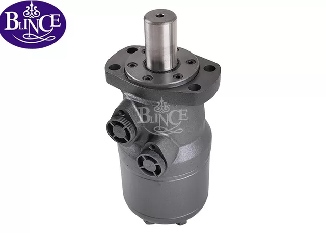
To successfully engineer these systems, selecting premium-grade pumps and motors is essential. As an industry-leading manufacturer with over two decades of fluid power expertise, BLINCE delivers a comprehensive portfolio of high-efficiency orbital motors, piston motors, and hydraulic pumps optimized for both open reservoir configurations and high-pressure closed loops. Our ISO 9001-certified production lines utilize advanced manufacturing tolerances to ensure exceptional reliability and power density, helping your equipment achieve peak operational performance regardless of the circuit layout.
When shortlisting a system architecture, evaluate strict footprint limitations, identify the primary actuator type, and assess the available cooling infrastructure. Next steps for implementation:
Conduct a comprehensive load-sensing analysis to determine exact flow and pressure requirements for all actuators.
Calculate the total heat rejection requirements to specify appropriate heat exchangers or reservoir dimensions.
Draft a hydraulic schematic detailing all filtration points, ensuring closed loops have adequate charge pump protection.
Establish a preventative maintenance schedule defining fluid sampling intervals and filter replacement metrics.
FAQ
Q: What is the fundamental difference between open and closed circuit hydraulic systems?
A: In an open circuit, fluid returns to a large atmospheric reservoir after powering the actuator. In a closed circuit, fluid flows in a continuous pressurized loop directly between the pump and the actuator, bypassing a main reservoir.
Q: Why do closed circuit hydraulic systems require a charge pump?
A: A charge pump replenishes fluid lost to internal leakage, maintains positive pressure at the main pump inlet to prevent cavitation, and circulates oil through heat exchangers for cooling.
Q: Which hydraulic circuit architecture is better for mobile equipment?
A: Closed circuits are generally superior for mobile equipment due to their compact size, lower weight, and ability to provide smooth, efficient bidirectional control for hydrostatic transmissions.
Q: How does reservoir sizing differ between open and closed loop hydraulics?
A: Open loops require large reservoirs to allow fluid to cool and contaminants to settle. Closed loops use very small reservoirs, only holding enough fluid to supply the charge pump.
Q: Can a single piece of machinery utilize both open and closed hydraulic systems?
A: Yes, many complex machines use both. An excavator might use a closed loop for its hydrostatic drive tracks and an open loop for its boom and bucket cylinders.
Q: What are the specific filtration requirements for closed loop hydraulic circuits?
A: Closed loops require highly efficient filtration, typically on the charge pump pressure line or suction line, because the continuous flow lacks a reservoir for particulates to settle out naturally.
Q: How does heat dissipation work in a closed loop hydraulic system?
A: Because fluid doesn't rest in a large tank, closed loops use a hot oil flushing valve to bleed a small amount of hot fluid from the main loop, replacing it with cooler fluid from the charge pump via a heat exchanger.