A hydraulic actuator moves slowly, the gauge reaches its set pressure, and the first proposed fix is to turn the relief valve up. That response sounds plausible because pressure is easy to see. Yet a pressure gauge does not tell you how much useful oil reaches the actuator, and raising a setting cannot change the geometric volume a pump displaces per revolution. Before changing a component or setting, separate the machine’s flow requirement from its pressure requirement.
The short answer
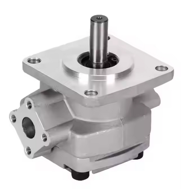
A hydraulic gear pump is a positive-displacement pump that uses rotating gears to carry oil from an inlet to an outlet. In a typical external gear design, the gears unmesh at the inlet, oil fills the spaces between the teeth and housing, and the rotating cavities carry it around the outside of the gears; the teeth mesh again at the outlet and displace that oil into the circuit. The pump creates flow. The circuit’s resistance to that flow creates pressure, within the limits of the pump and the rest of the system. A gear pump is a practical candidate when its displacement, shaft speed, pressure duty, inlet conditions, fluid, and interfaces match the machine. It is not automatically the right choice simply because it fits the mounting flange.
What is confirmed, and what still needs a model code
The description here concerns hydraulic external gear pumps unless a section says otherwise. It does not treat every gear pump—hydraulic, lubrication, fuel-transfer, or process-fluid—as interchangeable. A current BLINCE hydraulic pump category lists several pump families, while its hydraulic gear pump category groups gear-pump options. A category page confirms a product family exists; it does not prove that a particular model meets your machine’s pressure, speed, fluid, temperature, or duty requirements.
BLINCE’s published SGP product page identifies SGP1 and SGP2 models. Their displacement, pressure, speed, rotation, ports and mounting depend on the exact model code and configuration, so confirm each value against the current model table before ordering. BLINCE also lists an AZPW gear-pump series; check that series against its own current data rather than borrowing SGP values.
Picture two external gears rotating inside a close-fitting housing. On the inlet side, the teeth separate as they leave mesh. The expanding spaces lower local pressure, so oil from the reservoir enters to fill them. Oil then travels in pockets between the gear teeth and the housing wall around the outer circumference. At the outlet, the teeth come back into mesh and reduce the available pocket volume, pushing oil into the pressure port. Parker describes this sequence in its catalog’s general description of fixed-displacement D/H/HD pumps. A BLINCE gear-pump low-flow and noise guide also frames inlet supply, rotation, relief behavior, and wear as separate possible causes when the machine’s output changes.
The oil travels around the outside of the gears; it does not pass straight through the meshing center. This distinction helps explain why rotation direction and port layout matter. If the pump turns the wrong way for its construction, or if the inlet and outlet are identified incorrectly, the installed unit may not draw and deliver oil as expected. Do not infer a pump’s rotation from the engine’s viewpoint or from a photograph alone. Confirm the arrow or code on the pump and the maker’s definition of viewing direction, then check the circuit drawing. BLINCE’s rotation-direction and first-start checks describe the practical interface questions; its SGP series page shows why a series name alone is not the complete ordering code.
The housing and side plates keep the moving clearances small enough for the pump to carry oil while limiting internal leakage. Some designs use pressure-loaded or pressure-balanced plates to control clearances as load changes. Those construction details affect leakage, friction, and flow, but they do not remove the need for clean, compatible fluid or correct operation. Parker’s 2002 catalog describes a pressure-loaded wear plate in its own D/H/HD series; that design description cannot be generalized to every manufacturer or series. For a BLINCE product, use its own published gear-pump family listing and confirm material, fluid, seal, and port details against the selected code. A hydraulic contamination-control guide can help connect fluid cleanliness checks to observed wear without implying that all gear pumps tolerate abrasive particles.
Positive displacement does not mean guaranteed flow
The displacement, usually stated in cubic centimetres per revolution (cm³/rev) or millilitres per revolution (mL/rev), is the theoretical volume the pump moves per shaft revolution. At constant displacement, increasing shaft speed increases theoretical flow. A convenient estimate is:
This is a Calculated relationship, not a delivered-flow promise. Actual flow is lower or otherwise limited by internal leakage, inlet filling, fluid viscosity and temperature, pressure, wear, and the drive’s real speed under load. Compare the estimate with a manufacturer performance curve or a measured flow under the relevant operating conditions. BLINCE’s guide to hydraulic pump efficiency versus system efficiency helps keep component efficiency separate from what a machine ultimately uses; a guide to hydraulic oil viscosity explains why oil condition changes leakage and inlet behavior.
For a transparent Example, take a hypothetical 20 cm³/rev pump driven at 1,500 rpm. The theoretical flow is 20 × 1,500 ÷ 1,000 = 30 L/min. If, solely for illustration, volumetric efficiency at the stated condition were 0.90, estimated delivered flow would be 30 × 0.90 = 27 L/min. The assumed 90% is not a BLINCE product figure and should not replace a published curve or measurement. If the machine needs 28 L/min at operating temperature and pressure, this estimate says the candidate has no demonstrated margin; measure flow or select from model data rather than assuming the nominal displacement is sufficient. For background on complete model selection, start with the BLINCE hydraulic pump category and verify the exact SGP series page.
Fixed displacement describes the volume swept per revolution; it does not mean that the pump must always send the same measured flow into a machine function. A variable-speed drive can change shaft speed. A valve can divert or meter flow. A relief valve can return oil when pressure reaches its setting. Each method affects the system differently: reducing drive speed may reduce both flow and available actuator speed; throttling creates a pressure drop; and bypassing flow can consume input power while doing little useful work. To tell which path is active, identify valve states and measure flow and pressure at relevant points. A pressure-gauge placement guide covers why the measurement location matters, while the low-flow and noise troubleshooting guide separates pump wear from inlet or relief-path symptoms.
Pressure, flow, and drive power answer different questions
Flow is volume delivered over time; pressure is the force per area that develops as the circuit resists that flow. A pump does not select a pressure by itself in the way a pressure-compensated control might. In a typical fixed-displacement circuit, the load and restrictions determine the pressure required, while a relief valve limits pressure by opening at its set point. If an actuator is slow, low flow may be one cause, but so may a valve opening, leakage, a changed load, a speed reduction, or a restriction. A pressure reading at the pump outlet alone may not show the pressure available at the actuator. The BLINCE pressure test-point guide and pump troubleshooting article are useful when deciding where to measure before replacing parts.
Hydraulic power depends on both pressure and flow. In metric units, a common estimate is hydraulic power at the pump outlet (kW) = pressure at the outlet (bar) × delivered flow (L/min) ÷ 600. This is hydraulic output at the stated pump-port condition; shaft input must be higher to account for mechanical and volumetric losses. It does not mean every litre the pump produces is dissipated as heat. The energy path depends on where flow goes, the pressure difference across that path, and how long it operates. A BLINCE system-efficiency explanation distinguishes useful actuator work from losses; confirm product limits with the exact SGP series information.
Extend the earlier Example with explicit assumptions. Suppose 12 L/min actually passes across a relief or bypass path with 150 bar differential to a low-pressure return. The pressure drop across that path, Δp, is therefore about 150 bar in this simplified case. Dissipated hydraulic power is Δp × flow ÷ 600 = 150 × 12 ÷ 600 = 3 kW while that path is flowing. If the valve is closed and that flow instead does useful actuator work, this specific 3 kW loss does not occur. If return backpressure is significant, use measured pressure on both sides of the path and subtract; do not use outlet gauge pressure as a substitute for Δp. This calculation is an Example, not a claim that an unused portion of every pump’s flow is always wasted at full system pressure. It tells you to verify the route, differential pressure, flow and duration. BLINCE’s pressure measurement guide and low-flow diagnostic support that system-level check.
The shaft must also supply the torque and speed required by the pressure-flow duty. A larger displacement can raise flow at a given speed, but at the same pressure it also raises the drive torque demand; the motor, engine, coupling, shaft, and mounting must handle the resulting load. If the source cannot maintain its intended speed, actual flow will fall. If the pump draws through an undersized or restricted inlet, it may not fill the cavities, which can produce noise, heat, or damage. Before choosing a bigger unit, compare required operating flow, pressure, speed and power with the full pump curve and drive capability. The broader BLINCE pump category and gear-pump series listing help identify product families, while the coupling-alignment guide focuses on a mechanical issue that can affect the installation.
Where a fixed-displacement gear pump fits
A gear pump is worth evaluating when the application needs a relatively direct relationship between drive speed and pump displacement, and the operating points sit inside the selected model’s published limits. Its compact arrangement and gear-driven pumping action can suit mobile and industrial auxiliary circuits. Suitability still depends on duty: the load pressure, pressure duration, flow demand, allowable speed, fluid and temperature range, inlet arrangement, and mechanical interface. Treat the gear-pump category as a map of product options, not as a selection verdict. If the remaining choice is between gear arrangements, BLINCE’s internal-versus-external comparison covers that narrower decision.
The following table is a decision aid. It does not rank pump families universally; it shows what to check when a fixed-displacement gear pump is one candidate.
Machine requirement or observation
Why a gear pump may fit
Cost or limitation to weigh
Evidence to confirm before selection
Flow demand is stable at a known engine or motor speed
Displacement per revolution gives a useful first flow estimate
Delivered flow changes with pressure, oil, inlet filling, speed and wear
Required flow at operating temperature and load; pump curve or measured flow
A simple hydraulic circuit needs a fixed output
Few moving pumping elements can make the operating principle easy to understand
Flow still needs control or diversion when functions demand less than pump output
Circuit diagram, valve function, neutral-state path and bypass duty
The available envelope and drive suit a compact unit
Many gear-pump series offer a range of sizes and mounting arrangements
The flange may fit while shaft, rotation, ports or torque do not
Complete model code, mounting pilot, shaft and coupling dimensions, port standard
Pressure is within the chosen model’s continuous duty
A model-specific gear pump can operate at its published rating
A peak or intermittent number cannot be treated as continuous pressure
Continuous and intermittent duty definitions, duration, pressure at the pump
Low noise, low pulsation, low speed or variable flow dominates
A gear pump may still be viable if the exact model and system meet the target
Another architecture or control method may suit better; family labels do not prove behavior
Noise limit, speed range, required flow control, current datasheet and alternatives
If the machine needs a steady flow at one normal speed and uses valves suited to fixed output, a gear pump may be a straightforward candidate. If it spends long periods with most pump output bypassed, needs flow to vary efficiently with demand, runs outside the available speed range, or has a special low-noise requirement, compare another architecture or control approach. That comparison is not simply “gear versus piston”: the system’s duty and the product’s published envelope decide. BLINCE’s wider pump category and gear-pump products can help establish which families exist; the SGP page gives series-specific fields that must be matched to the actual job.
A practical selection sequence
Start with the machine function, not a pump headline. Write down what must move, how quickly, under what load, and how often. If the machine is already operating, record when the symptom occurs: cold or hot, unloaded or loaded, one function or several, and before or after a recent service. These conditions help separate a sizing decision from a fault investigation. A slow cylinder under load may need more useful flow, but it may also reflect internal leakage, a relief path, control-valve behavior, or lost prime. The gear-pump troubleshooting guide and no-suction diagnostic can guide separate checks.
Next, estimate flow from displacement and real shaft speed, then compare it with the machine requirement at the relevant operating point. If the requirement is 27 L/min but the ideal displacement-speed calculation gives 30 L/min, the theoretical headroom is only 3 L/min before losses. Do not apply an assumed efficiency factor as if it were a universal correction. Get the selected model’s flow curve at the relevant pressure, speed, oil and inlet condition, or measure the machine. BLINCE’s hydraulic pump category complements its SGP series listing, but model selection still depends on the complete duty.
Then document pressure as a profile rather than a single maximum. Record continuous pressure, intermittent pressure, any short peak, the duration of each, and the return pressure where relevant. Check whether pressure at the pump is being mistaken for pressure at the actuator, and identify whether the relief valve opens during normal work. A single gauge reading may hide line losses or an unintended bypass. Use named measurement points and the correct rated instruments; do not alter settings as a diagnostic shortcut. BLINCE’s pressure measurement guide explains location effects, while its gear-pump product category helps identify model families whose datasheets must be checked.
Check the inlet and fluid before interpreting low output as a worn pump. The pump must be able to receive oil at the required speed and viscosity. A restricted strainer, small suction line, blocked breather, low reservoir level, air leak, cold high-viscosity oil or poor hose routing may prevent proper filling. Warm oil can reduce viscosity and reveal leakage that was less visible at startup; cold oil can increase inlet losses. Compare oil grade and actual temperature with the model’s limits. The oil-viscosity guide and contamination-control guide help organize these checks, and the no-suction article focuses on inlet symptoms.
Finally, match the hardware interface and installation details. Verify rotation from the shaft end as defined by the manufacturer; identify inlet and outlet ports; compare flange standard, pilot diameter, shaft form, coupling engagement, port thread or flange, seal materials, and envelope. Check alignment and side loading against the pump maker’s instructions. A unit that bolts into place can still rotate the wrong way, connect to incompatible lines, overload a shaft, or fail to prime. BLINCE’s rotation and commissioning checks and coupling guide address separate parts of that fit-up; compare them with the pump’s own drawing and the machine manual.
Common mistakes that lead to the wrong decision
A pressure rating is not the pump’s normal output. It defines a boundary under stated conditions; the circuit and load determine working pressure, while a relief or control element may limit it. Read continuous, intermittent and peak labels as the selected manufacturer defines them. BLINCE’s SGP product information points readers to model-specific fields, and the wider pump category shows why a figure from one family cannot be transferred to another.
A pressure adjustment is not a flow control. At a given displacement and speed, pressure does not increase theoretical flow. Raising a relief setting may allow the machine to reach a load it previously could not move, so motion may return in that specific case; once it moves, speed still depends on useful flow and load. An adjustment can also increase force and drive demand and may exceed component limits. Check the machine manual, actual pressure profile and delivered flow before changing settings. The gauge-placement guide helps identify where a reading came from; the system-efficiency article explains why an unintended pressure drop can consume power.
Displacement alone does not specify an operating point. Displacement × rpm gives a useful theoretical estimate, but a pump must also meet pressure, inlet, temperature, speed, fluid, drive and interface requirements. If actual speed differs from the assumed engine speed, the estimate changes; if leakage is high at the operating condition, delivered flow falls further. Confirm with performance data for the exact model. The SGP series page and flow-estimation guide belong together for that reason.
Blaming the pump before checking the path to it. An inlet restriction, air ingress, low reservoir level or clogged filter may produce noise or low output that resembles pump wear. A relief valve that remains open, a control valve leaking internally, or a load that has changed can also affect the machine. Compare cold and hot behavior, unloaded and loaded flow, pressure at named points, and oil condition before authorizing a replacement. BLINCE’s no-suction diagnostic and contamination-control checks cover two upstream causes; its low-flow guide brings several branches together.
Copying only the old flange and shaft. A replacement can fit mechanically and still have the wrong rotation, displacement, pressure duty, port configuration, seal, or speed range. Photograph the nameplate and connections, but capture the complete model code and dimensions as well. The manufacturer defines the viewing direction for rotation; “clockwise” without that viewpoint is ambiguous. BLINCE’s first-start and rotation guide and SGP product page help frame the information, but the actual replacement still requires drawing-to-machine verification.
Assuming bypass heat always equals pump flow times relief pressure. That shortcut is valid only when the stated flow actually crosses a path with that pressure drop, for that duration. Flow used by an actuator is not automatically dissipated across a relief valve. Return pressure, other valve paths, simultaneous functions and duty cycle all matter. Measure or determine the pressure difference across the relevant restriction and the flow through it. The system-efficiency guide and pressure measurement guide support this distinction.
When to pause before buying or adjusting
Do not finalize a pump choice when the required flow, pressure duration, operating speed, fluid or inlet condition is unknown. Pause if the only compatibility evidence is a similar-looking casting, a matching bolt pattern, or an unverified catalog headline. Stop and obtain the machine’s approved procedure when the circuit supports a suspended load, braking, steering or another safety-critical function; the correct architecture and adjustment process must come from the machine manufacturer and qualified service personnel. Pause as well if the intended pressure or speed exceeds the exact candidate’s published continuous envelope, or if the selected fluid and seal combination is not documented. The BLINCE pump-family listing and SGP details can identify questions for the supplier; they do not replace the machine manual or a current model datasheet.
Information to put in a quote request
Send enough evidence to check both the pump and the circuit:
Machine make, model, function served, load, target motion, and duty cycle.
Required or measured flow, pump speed, and how each value was obtained.
Continuous, intermittent and peak pressure, with duration and measurement location; return backpressure if known.
Hydraulic schematic or clear photos of the pump, valves, inlet path, reservoir and return route.
Oil type and viscosity grade, cold-start and normal oil temperature, contamination or filter history, and any recent service.
Complete old pump model code and nameplate photo; rotation convention, flange/pilot, shaft and coupling dimensions, port type and orientation.
Drive type and available power, plus the exact machine manual or approved pump specification if available.
Those details turn “I need a gear pump” into a checkable operating point. The BLINCE gear-pump category and pump-family category provide a place to identify candidate families after the duty is clear. If the issue is a slow or noisy existing circuit, attach measurements and symptom timing so the discussion can distinguish selection from troubleshooting; the low-flow guide shows why the distinction matters.
Frequently asked questions
Does a gear pump create pressure?
The pump supplies flow. Pressure develops when the circuit resists that flow, such as when moving a load or passing through a restriction. A relief valve may limit pressure, but the pump’s pressure rating is a maximum operating boundary under specified conditions, not a pressure it produces continuously by itself.
Is every gear pump fixed displacement?
Many common hydraulic external gear pumps are fixed displacement, meaning their swept volume per shaft revolution is set by their geometry. That does not mean measured outlet flow is perfectly constant: speed, internal leakage, oil condition, inlet filling and operating pressure affect delivery. Confirm the construction and performance curve for the exact product.
Can a gear pump run in reverse?
Only when the pump is designed and configured for the intended rotation and flow direction. Shaft-seal arrangements, internal porting and case-drain details vary. Do not reverse a motor or swap lines on assumption alone; check the manufacturer’s instructions and the machine circuit drawing. BLINCE’s rotation-direction article is a useful preliminary checklist.
How do I know whether the pump is worn?
One symptom or one pressure reading cannot establish wear. Compare delivered flow at the relevant speed, oil temperature and load with the exact model’s performance data, while checking the inlet, relief path, valves, fluid and drive. A change from cold to hot operation can be informative, but it is not conclusive by itself. Use a qualified test procedure and the machine manual.
Is a larger-displacement pump always better?
No. A larger displacement can raise theoretical flow at a given speed, but it also raises flow beyond what the circuit may use and can increase drive torque demand. If excess flow passes through a throttling or relief path, power may be lost there. Size for the required flow and duty, and verify the drive, inlet and control arrangement.
What is the difference between internal and external gear pumps?
They use different gear arrangements and have different sealing and operating characteristics. “Gear pump” alone does not identify one architecture. Selection depends on the required pressure, flow, speed, fluid, noise, control and cost at the duty point. BLINCE’s separate internal-versus-external comparison examines that narrower choice; verify its cited model limits against current documents before applying them to a different pump.
The useful next step
If you are selecting or replacing a unit, send the complete pump code, the machine function, required flow and speed, pressure profile, oil and temperature range, inlet arrangement, drive details, and interface measurements. BLINCE can use those records to identify missing confirmations, compare candidate series against the stated duty, and flag interface or operating-envelope mismatches before a quotation is finalized. Do not send a pressure target alone and expect it to establish pump suitability.
This article is a general engineering guide. Final component selection should be based on machine drawings, measured hydraulic data, working conditions, safety requirements, and confirmation from a qualified hydraulic engineer or supplier.
Blince Hydraulic Team
Blince Hydraulic is an industry-leading company dedicated to precision-engineered fluid power manufacturing and custom hydraulic solutions. Backed by decades of deep field expertise in industrial machinery and thousands of successful global deployments, our engineering team focuses entirely on high-performance hydraulic component manufacturing, including specialized orbital motors, high-pressure travel drives motor, and robust directional control valves. Our production infrastructure utilizes state-of-the-art multi-axis CNC machining systems and is fully ISO 9001 certified to guarantee repeatable volumetric accuracy across every single manufacturing run.
We deliver fast, highly dependable, and cost-efficient hydraulic solutions to heavy industry distributors, machinery OEMs, and maintenance crews across more than 150 countries. Whether your active project calls for a small-volume batch of customized shaft profiles or a large-scale production run of severe-duty cast iron gear pump, we configure our flexible production schedules to meet your target lead times with total pricing predictability. Partnering with Blince means securing maximum system efficiency, elite material quality, and uncompromised fluid power professionalism.
To learn more about our complete product lineup, visit our official website: www.blince.com.