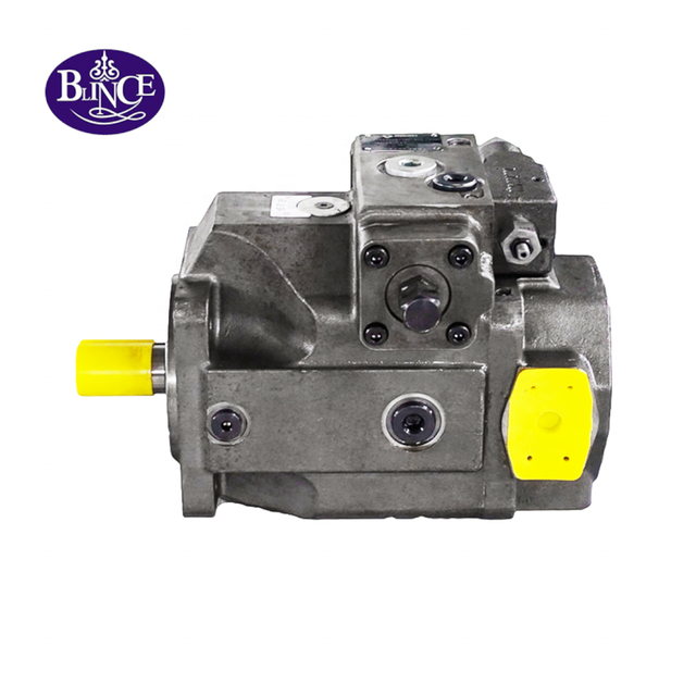
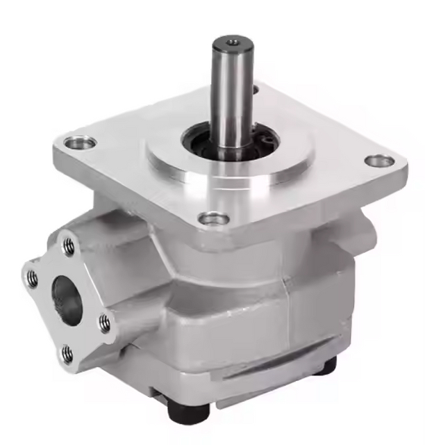
A pattern repeats in repair shops. A gear pump fails on a machine that runs lightly for most of the year. The replacement arrives with a matching flange, a matching splined shaft and matching port spacing. It bolts straight on. Weeks later the same complaint is back: the machine is slow once the oil is hot.
Nothing about that outcome requires a dishonest part. It requires a duty that was never checked.
The internal-versus-external question is usually framed as "which pump is better." That framing produces a table nobody can act on, because both architectures are fixed-displacement positive-displacement pumps and both will move oil. The question that changes a purchase order is narrower: does this duty fall outside what a correctly sized external gear pump can hold, and if so, what specifically forces the internal-gear route?
Short Answer
For most mobile and industrial auxiliary circuits running ISO VG 32–46 oil between roughly 1,000 and 2,500 rpm at continuous pressure up to about 200–250 bar, a correctly sized external gear pump is the cheaper, smaller and faster-to-source answer. An internal gear pump becomes worth its extra cost and envelope when the duty combines low drive speed, high viscosity, high continuous pressure and a noise or pulsation limit that the external pump cannot meet. The boundary is set by four published numbers — displacement, speed range, pressure rating and viscosity window — plus one measurement: flow at hot oil and working pressure. Confirm all five before ordering, because mechanical fit proves nothing about hydraulic fit.
Evidence Boundary: What Is Confirmed on This Page
Numbers on this page carry one of four labels. Published means the figure appears in a current BLINCE product page or in a public manufacturer document from Bosch Rexroth or Parker Hannifin. Counted means it was derived from published values through arithmetic shown on the page. Example means it illustrates a method and is not a product promise or a record of a real repair. Confirm by datasheet means the answer depends on the complete model code, drawing or test procedure and cannot be settled from a web page.
Two technical documents carry most of the comparison below, and both were checked directly rather than quoted from a summary: the Bosch Rexroth PGH internal gear pump data sheet for the gap-compensated internal gear side, and the Parker PGP/PGM 500 series catalog for the pressure-balanced external gear side. Where this page describes how a BLINCE pump behaves, the source is the current BLINCE hydraulic gear pump category, the SGP1 and SGP2 series page and the individual series pages linked below. Nothing here is drawn from a competitor's performance claim, and no search-snippet figure is treated as a specification.
What Actually Differs Inside the Two Pumps
An external gear pump uses two similar gears that mesh with each other inside a housing, with the oil carried around the outside of both gears in the tooth spaces. Sealing depends on close clearances between the gear faces and the side plates, and between the gear tips and the housing bore. Parker describes its PGP 500 series as an aluminum external gear pump with pressure-balanced bearing blocks that maintain efficiency across the operating range, published in three frame sizes with displacements from 2 to 52 cm³/rev (Parker catalog HY09-0500/US). BLINCE builds the same family of architecture in the HGP series and the AZPW series, both published with a maximum working pressure of 250 bar.
An internal gear pump works differently. A small externally toothed pinion drives a larger internally toothed ring gear, and a crescent-shaped filler element separates the suction chamber from the pressure chamber. Bosch Rexroth describes its PGH type as a gap-compensated internal gear pump in which axial compensation forces press the axial washers against the rotating parts while radial compensation presses the segment filler against the pinion and ring gear head diameters, keeping the leakage gaps extremely small (Rexroth RE 10223/2019-02). That compensation is the whole reason an internal gear pump holds efficiency at low speed and high viscosity, and it is also why the architecture costs more. The involute internal tooth system, with its long meshing length, is what produces the low flow pulsation that shows up as quieter operation on the machine. It is also the reason the comparison on this page is written against BLINCE's external gear range, listed in the hydraulic gear pump category and inside the wider hydraulic pump category, instead of against a product line that does not exist.
The practical consequence is not "internal is better." It is that the two architectures lose flow in different places. If you want the background on how delivered flow departs from theoretical flow across pump families, the existing BLINCE guide to how to calculate hydraulic pump flow rate for different machines works through the same arithmetic from a different starting point, and the gear pump selection guide shows how that arithmetic turns into a published size.
The Four Numbers That Decide Between Them
Displacement. Displacement sets theoretical flow at a given drive speed, and the two architectures are published in overlapping but not identical size ranges. Rexroth publishes the PGH internal gear pump from 5.24 to 16.0 cm³/rev. Parker publishes the external gear PGP 500 from 2 to 52 cm³/rev. BLINCE publishes the external gear SGP1 and SGP2 series at 19–36 mL/r and 20–52 mL/r respectively. If the duty needs 12 cm³/rev, an internal gear pump may be a candidate. If it needs 45 cm³/rev, the internal-gear comparison is over before it starts, and the decision moves to which external gear series carries the pressure you need at that displacement. The broader hydraulic pump category shows how gear, vane and piston ranges divide that work.
Speed range. Speed decides whether a given displacement produces the flow the machine needs, and it also decides whether the pump is operating in the region where its clearances behave predictably. Rexroth publishes the PGH internal gear pump from 600 to 3,000 rpm. Parker publishes the external gear PGP 500 from 500 to 4,000 rpm, with a minimum speed of 500 rpm at maximum outlet pressure and a maximum speed that falls from 4,000 rpm at 2 cm³/rev to about 2,400 rpm at 11–12 cm³/rev. BLINCE publishes the SGP1 range at 600–2,500 rpm rated with 3,000 rpm maximum, and the SGP2 range at 400–3,000 rpm. The HGP series and the AZPW series publish their speed band next to pressure and displacement rather than as a single headline figure, because the usable range moves with the size. A duty that must run at 300 rpm under full pressure sits outside all of these published windows and needs a different architecture, not a different brand.
Pressure rating. This is the number most often compared and least often read correctly, because continuous and intermittent ratings behave differently. Rexroth publishes the PGH internal gear pump at 315 bar continuous and 350 bar intermittent on mineral oil, dropping to 210 bar continuous and 230 bar intermittent on special fluids. Parker publishes the PGP 505 external gear frame at 275 bar continuous and 300 bar intermittent for the 2–8 cm³/rev sizes, falling to 250 bar continuous for the larger sizes in that frame. BLINCE publishes the SGP1 and SGP2 series at 20 MPa rated and 25 MPa maximum, and at 24.5 MPa rated and 29.4 MPa maximum respectively. The comparison is only meaningful if you use the continuous figure, because a machine that holds its relief setting loaded for hours is a continuous duty even if the pressure gauge barely moves, and that is the figure the gear pump selection guide works from.
Viscosity window. Viscosity is where the two architectures separate most visibly on a real machine. Parker publishes the PGP 500 operating viscosity range as 8 to 1,000 mm²/s, with a cold-start window of 1,000 to 2,000 cSt permitted only at operating pressure at or below 10 bar and speed at or below 1,500 rpm, and a fluid temperature range of −15 °C to +80 °C. Rexroth states that the PGH internal gear pump is suitable for broad viscosity and speed ranges and specifically credits sealing gap compensation with maintaining high efficiency at low speed and low viscosity. The general behaviour of oil grade against temperature and leakage is covered in the BLINCE guide to hydraulic oil viscosity, and the difference between a pump's own efficiency and the efficiency the machine finally sees is set out in hydraulic pump efficiency vs system efficiency.
Worked Example: Where an External Gear Pump Loses Its Flow
The calculation below is labelled Example. It shows the method; it is not a claim about any BLINCE pump, and it is not a customer case. Substitute your own measured values.
Start with the requirement. An auxiliary circuit on a mobile machine needs 25 L/min at 200 bar with the oil at 70 °C, and the pump is driven directly at 1,500 rpm. Published displacement needed at 100% volumetric efficiency:
Vg = Q x 1000 / nVg = 25 x 1000 / 1500 = 16.7 cm3/rev (Calculated, theoretical)
Select a published size above that figure. The BLINCE SGP2 series includes a 20 mL/r unit, published at 24.5 MPa rated pressure, so theoretical flow at 1,500 rpm is:
Qt = 20 x 1500 / 1000 = 30.0 L/min (Calculated)
Now measure. With the oil hot and the circuit loaded to 200 bar, the pump delivers 26.0 L/min. Volumetric efficiency and slip follow directly:
Efficiency_v = 26.0 / 30.0 = 86.7% (Calculated, from Example values)Slip = 30.0 - 26.0 = 4.0 L/min at 200 barSlip coefficient = 4.0 / 200 = 0.020 L/min per bar
The useful part of that number is what it predicts. At the machine's relief setting of 250 bar, and assuming slip stays roughly proportional to pressure difference across the same clearances:
Q at 250 bar = 30.0 - (0.020 x 250) = 25.0 L/min (Calculated, Example)Efficiency_v at 250 bar = 25.0 / 30.0 = 83.3%
Read that against the requirement. The pump was chosen for 30 L/min and the machine needs 25 L/min. At 200 bar there is 1.0 L/min of margin. At 250 bar the predicted delivered flow lands exactly on the requirement, which means there is no margin left at all. Hydraulic power at the measured operating point puts the size of the job in perspective as well:
P_hyd = p x Q / 600 = 200 x 26.0 / 600 = 8.67 kW (Calculated)Input power at 0.85 overall efficiency = 8.67 / 0.85 = 10.2 kW
The decision this changes is the order, not the arithmetic. A pump sitting at 83–87% volumetric efficiency hot is not yet a failed pump, but its margin is gone. Slip rises as side plates and gear tips wear, so the same machine will be short of flow within a service interval. Two honest routes exist: move up one displacement size in an external gear pump and accept a larger drive power, or move to an internal gear pump if the duty also involves low speed, high viscosity or a noise limit. What you should not do is repeat the previous order and hope the hot-oil symptom was the old pump's fault alone. Pressure and flow measurements that separate pump slip from relief bypass follow the same logic as the test points in the BLINCE guide to hydraulic pressure gauge placement, and the wear path behind a low-flow complaint is described in the gear pump low flow and noise troubleshooting guide.
Decision Table: Match the Duty to the Architecture
The table is deliberately written as a routing tool. Read down the first column until you recognise the machine condition, then treat the last column as the check that has to pass before money moves.
Observed condition or constraint
Direction
Benefit of that direction
Cost, limitation or failure risk
What must be confirmed first
Low drive speed (below roughly 600 rpm) at high continuous pressure, with high-viscosity or cold-start oil
Internal gear, gap-compensated
Published for broad speed and viscosity ranges with high efficiency at low speed and viscosity; low flow pulsation
Higher purchase cost, larger envelope for the same displacement, longer replacement lead time, tighter availability
Published speed and viscosity window for the exact size, plus shaft, flange and port standard
Auxiliary circuit at 1,000–2,500 rpm, continuous pressure at or below about 250 bar, ISO VG 32–46 oil
External gear
Compact, light, low cost, widely stocked, simple to service, many mounting and port options
Volumetric efficiency falls as oil thins and as side plates and tips wear; little margin left once slip rises
Hot-oil flow at working pressure, inlet condition, ISO 4406 cleanliness target, drive coupling alignment
Pump must hold full pressure below about 500 rpm
Neither, as ordered
—
Below the published minimum speed at maximum outlet pressure, flow becomes erratic and wear concentrates
Minimum speed at maximum outlet pressure from the current data sheet, then re-open the architecture question
Machine runs water-based or fire-resistant fluid
Whichever passes fluid approval
Correct seal and material combination keeps the pump inside its published fluid list
The wrong seal design fails early even when pressure and speed match; some fluids cut the allowable pressure
Approved fluid classification and matching seal design for the exact model
Replacement bolts on but the machine is still slow when hot
Stop the order
Prevents a second wrong purchase
Mechanical fit proves nothing about displacement, speed or internal condition
Measured flow at hot oil and working pressure, relief behaviour, and inlet vacuum
Displacement needed is above roughly 16–20 cm³/rev with a compact envelope
External gear
Published across a wider displacement range in small frames
Larger displacement reduces the maximum published speed in the same frame
Maximum speed at the required displacement, not the frame's headline maximum
Tradeoffs You Cannot Avoid
Noise and pulsation trade against cost and envelope. An internal gear pump with an involute internal tooth system and a long meshing length produces characteristically low flow pulsation, and that is a genuine advantage on machine tools, presses and any installation where the pump sits close to an operator. Paying for it means accepting a larger pump for the same displacement, a longer lead time and a higher unit price. If the noise or the failure comes from a suction restriction or a misaligned coupling rather than from the architecture, that money buys nothing, which is why the checks in the pump coupling alignment guide belong before the specification decision. When a pump has already failed more than once, the assembly details that cause a repeat — coupling fit, rotation direction and first start — are covered in the gear pump rotation direction guide, and they usually cost less to correct than a change of architecture.
Efficiency retention trades against simplicity and supply. Gap compensation keeps leakage gaps small as pressure and viscosity change, which is exactly what a low-speed, high-viscosity duty needs. The same mechanism adds precision parts and cost, and it does not remove the need for clean oil. Where a BLINCE external gear pump is the correct answer, the requirement does not disappear either. The SGP2 series is published with axial clearance compensation, radial hydraulic balance, bi-metal side plates and DU bearings, so service life still depends on inlet condition and contamination control; the contamination control guide covers the first of those, and the wear path that opens up when clean oil and a correct inlet are not maintained is described in the gear pump low flow and noise troubleshooting guide.
Pressure headroom has to be weighed against every other number, and it is the one where buyers most often reach for a bigger figure than the machine needs. Published ratings are tied to displacement, frame size, fluid and temperature, and they are bounded by line losses, return-path restrictions and heat that the pump cannot cause but must survive. On a circuit already running near its continuous rating, the more productive next step is usually to check the hydraulic pump category for a different architecture rather than to search for a higher-rated gear pump, and the difference between a vane pump and a gear pump in that pressure-and-flow region is worth understanding before the specification is frozen.
Checks to Run on the Machine Before You Order
Start at the inlet, because an inlet problem will follow the new pump into the machine. Measure vacuum at the pump inlet with the oil hot, and compare it with the published inlet pressure range: Rexroth publishes 0.8 to 2 bar absolute for the PGH, with 0.6 bar permitted briefly at start, and Parker publishes −0.8 to 2 bar with a 0.5 bar minimum for the PGP 500. If the reading is outside that band, the fault is upstream and no architecture change will fix it. The diagnostic path for a pump that will not draw oil is set out in why your hydraulic pump is not drawing oil, and the flow arithmetic that shows what the pump should be delivering at that drive speed is in how to calculate hydraulic pump flow rate.
Then measure the two temperatures that matter, because a single cold reading misleads. Record oil temperature at cold start and after the machine reaches working temperature, because the published cold-start allowances are narrow: Parker permits 1,000 to 2,000 cSt only at or below 10 bar and 1,500 rpm, and a machine that accelerates hard while the oil is still thick is outside that allowance whatever the pump brand. Recording the hot temperature also gives you the viscosity at which your flow measurement was taken, which is the only way to compare two pumps fairly. A reading without a recorded test point invites a false conclusion of the kind described in the hydraulic pressure gauge placement guide. The relationship between grade, temperature and leakage is set out in the BLINCE hydraulic oil viscosity guide.
The mechanical interface is a separate decision from the hydraulic one, and it deserves its own pass. Rotation direction, shaft style and end cover, flange standard, port position and port type all have to match, and a thread or flange match on its own proves nothing about drive compatibility. BLINCE publishes the HGP and AZPW series with right rotation as standard and left rotation available, and the SGP1 series as a compact low-noise unit intended for hoisting, conveying, road and light-industry machinery; the published ranges for that family sit on the SGP1 and SGP2 series page. The first-start sequence itself is in the gear pump rotation direction guide.
One more record decides how honest the sizing is: how the machine actually uses the pump over a cycle, not what the nameplate says. A circuit that holds pressure for most of an eight-hour shift is a continuous duty, and the continuous rating is the one to compare — the point where held pressure turns into heat instead of work is the subject of the guide to pump efficiency vs system efficiency. A circuit that reaches peak pressure for a few seconds per cycle can sometimes be matched to an intermittent rating, but only when the manufacturer's published definition of intermittent matches your actual duty, and the gear pump selection guide shows how a duty is normally written down before a size is fixed. If the machine's own duty definition is unclear, size against the continuous published figure and treat any headroom as margin rather than as a design target.
Common Mistakes in Internal vs External Gear Pump Decisions
Choosing by mechanical fit is the mistake that costs the most. A pump that bolts on has proven that its bolt pattern fits; it has not proven its displacement, its speed range at the required pressure, its viscosity window or its internal condition. Because the flange and shaft are the easiest things to photograph, they tend to become the whole specification. The check that belongs in front of the purchase order is the measured flow at hot oil and working pressure, which is also the check that separates a genuinely undersized pump from a worn one. The wear pattern itself is described alongside relief and suction faults in the gear pump low flow and noise troubleshooting guide, and the broader question of how delivered flow relates to speed and displacement is worked through in how to calculate hydraulic pump flow rate.
A second assumption worth testing early is that an internal gear pump is simply the more efficient choice. Published data does not support a blanket claim. The advantage documented by Rexroth is efficiency at low speed and low viscosity plus low pulsation, achieved through sealing gap compensation. For a 2,000 rpm auxiliary circuit on ISO VG 46 oil at 180 bar, that advantage may never appear, while the larger envelope, higher price and longer lead time appear immediately. Comparing two architectures honestly means comparing them at your operating point, not at the corners of their catalogs, and the gear pump selection guide sets out how that comparison is normally run. Pump efficiency and system efficiency are also not the same number, and the difference between them is set out in the BLINCE guide to pump efficiency vs system efficiency.
Measuring flow once, when the pump is new and the oil is cold, closes the case far too early. A cold reading flatters a worn pump because thick oil seals the clearances that hot oil will open, and a single new-pump reading hides the rate at which slip is increasing. Two readings — one at hot working temperature, one at the relief setting — give you both the current efficiency and a first estimate of the slip coefficient, which is the number that tells you how much service life is left before the machine is short of flow. If the machine has a return-path restriction or a back-pressure problem, that measurement belongs in the record too, because it changes the pressure difference across the pump rather than the pump's displacement. The two checks that most often discredit a cold flow reading are coupling condition, covered in the pump coupling alignment guide, and an inlet that is not fully flooded, covered in the not drawing oil diagnostic.
When to Stop and Not Buy Either Pump
Some duties should pause the order rather than choose an architecture. Stop if the required continuous pressure sits above the published continuous rating of every candidate, because moving to the intermittent figure to make the numbers work is a decision about warranty and service life, not about suitability. Stop if the machine must hold full pressure below the published minimum speed at maximum outlet pressure, because neither architecture in its standard form solves that. Stop if the required fluid is not on the published approved-fluid list for the model you intend to order, since seal and material compatibility is a published boundary rather than a negotiable one. Stop if a load must be held after the pump stops, because a fixed-displacement pump is not a load-holding device and that requirement belongs to a valve or brake decision. Stop if an interface dimension is unmeasured, or if the complete original model code, shaft style, flange standard and port arrangement are unknown. Stop if the machine's own manual specifies a pump architecture or a control function that the candidate pump cannot provide, and defer to that manual. Where several of those blocks apply at once, the answer is often a review against the wider hydraulic pump category rather than another gear pump order, and the difference between a vane pump and a gear pump is usually the first comparison worth making. Each of these blocks is removable. When you remove it by supplying the missing measurement or document, the architecture question usually answers itself.
One further pause applies to this specific topic. If your only reason for considering an internal gear pump is that the machine is noisy, isolate the noise source first. Suction restriction, coupling misalignment, air entrainment and a relief valve operating continuously all produce noise that a gap-compensated pump will reduce only partially. Aeration and fluid condition are worth ruling out through the contamination control guide, and an inlet that is not fully flooded through the not drawing oil diagnostic; both cost far less than a change of architecture and often remove the complaint entirely.
Data to Send for a Pump Review
Group the data so it can be read in one pass, and treat any missing field as a reason to wait rather than a reason to guess.
Machine and duty: machine function, drive source, direct or belt drive, continuous or intermittent cycle, hours per day at pressure.
Performance: required flow at working pressure, drive speed, continuous pressure, intermittent or peak pressure, relief setting, pressure at named points.
Fluid and temperature: oil grade, viscosity at the measured temperature, cold-start temperature, normal oil temperature, maximum oil temperature, contamination target.
Interfaces: complete original model code, shaft style and size, flange and mounting standard, rotation direction, port type and position, envelope limits.
Circuit and symptom: inlet layout and measured vacuum, return-path restriction, filtration, cooling, what the machine does when the fault appears, whether the symptom is worse cold or hot.
Evidence: nameplate photograph, marked installation photographs, drawing, flow and pressure test readings with the temperature they were taken at, and any previous failure debris.
FAQ
Is an internal gear pump more efficient than an external gear pump?
Not as a general rule. Bosch Rexroth publishes its PGH internal gear pump as efficient at low speed and low viscosity because of sealing gap compensation, and as low in flow pulsation. That is a conditional advantage. At high speed on thin oil, the gap compensation matters less, while the internal gear pump's cost, envelope and lead time remain.
Can I replace an internal gear pump with an external gear pump if the flange fits?
Only after the duty checks pass. Displacement at the actual drive speed, continuous pressure rating, viscosity window, rotation direction and inlet condition all have to match the new pump's published range. A matching flange and shaft confirm the mechanical interface and nothing else.
Why does my gear pump deliver enough flow when cold but not when the oil is hot?
Thinner hot oil leaks more readily through the pump's internal clearances. Volume lost that way is slip, and slip rises with both pressure difference and wear. Measuring flow at hot working temperature, then again near the relief setting, is what separates a worn pump from one that was undersized in the first place.
What is the maximum pressure for a gear pump?
It depends on the series, the displacement, the frame size and the fluid. Bosch Rexroth publishes a 315 bar continuous and 350 bar intermittent rating on mineral oil for one internal gear pump range. Parker publishes 275 bar continuous for the smaller sizes in one external gear frame, falling with displacement. BLINCE publishes 20 MPa rated and 25 MPa maximum for the SGP1 series, and 24.5 MPa rated and 29.4 MPa maximum for the SGP2 series. Always compare continuous duty against the continuous figure for the exact size.
Do BLINCE gear pumps include an internal gear pump series?
No. The current BLINCE range covers external gear pumps, including the HGP series, the AZPW series and the SGP1 and SGP2 series. Where a published duty genuinely requires an internal gear pump architecture, the honest answer is that BLINCE is not the right supplier for that position, and the review below will say so rather than propose a substitute that does not match the duty.
How much does an internal gear pump cost compared with an external one?
This page does not quote prices, because a meaningful comparison has to be made on the exact displacement, pressure rating, mounting, port arrangement and quantity. What can be compared without price is the set of demands each architecture places on the machine: envelope, drive power, filtration and lead time.
The Next Step
Send the machine function, the required flow at working pressure, the drive speed, the continuous and peak pressure, the oil grade with cold and hot temperatures, the measured inlet vacuum, the complete original model code, and photographs of the nameplate and the mounting. Include the flow and pressure readings you already have and the temperature at which each was taken.
With that in hand, BLINCE can return a specific answer rather than a catalog page: which external gear series and displacement fits the published duty, which of your numbers falls outside every candidate's published range, whether the application points toward an internal gear architecture that BLINCE does not supply, and which measurements are still missing before a quotation would be worth reviewing. If the honest answer is that the duty needs a different architecture, you will get that answer before you place an order.
This article is a general engineering guide. Final component selection should be based on machine drawings, measured hydraulic data, working conditions, safety requirements, and confirmation from a qualified hydraulic engineer or supplier.
Blince Hydraulic Team
Blince Hydraulic is an industry-leading company dedicated to precision-engineered fluid power manufacturing and custom hydraulic solutions. Backed by decades of deep field expertise in industrial machinery and thousands of successful global deployments, our engineering team focuses entirely on high-performance hydraulic component manufacturing, including specialized orbital motors, high-pressure travel drives motor, and robust directional control valves. Our production infrastructure utilizes state-of-the-art multi-axis CNC machining systems and is fully ISO 9001 certified to guarantee repeatable volumetric accuracy across every single manufacturing run.
We deliver fast, highly dependable, and cost-efficient hydraulic solutions to heavy industry distributors, machinery OEMs, and maintenance crews across more than 150 countries. Whether your active project calls for a small-volume batch of customized shaft profiles or a large-scale production run of severe-duty cast iron gear pump, we configure our flexible production schedules to meet your target lead times with total pricing predictability. Partnering with Blince means securing maximum system efficiency, elite material quality, and uncompromised fluid power professionalism.
To learn more about our complete product lineup, visit our official website: www.blince.com.