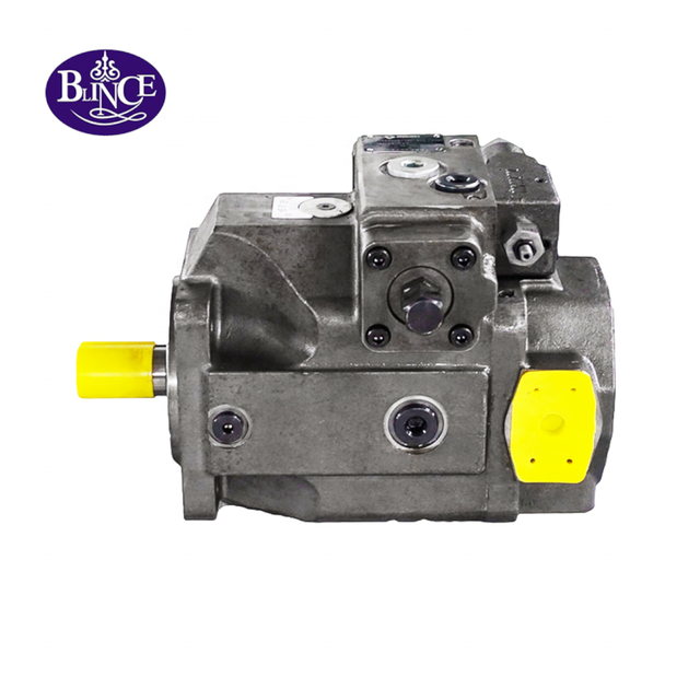
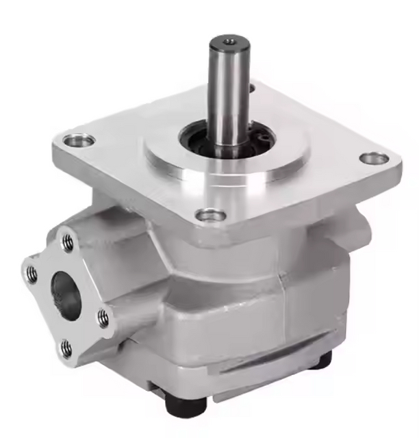
A hydraulic pump that fails early is easy to blame. The new pump is noisy. The shaft seal starts leaking. The coupling insert breaks. The bearing area feels hot. The machine runs for a week, then the same failure returns. Someone says the pump quality is poor, someone else asks for a larger pump, and the old installation remains untouched.
That habit gets expensive fast. In the field, a hydraulic pump may be the first part to make noise, leak, or run hot even though the trouble started beside it. I would look at the coupling, the bracket, the suction line, the pipe load, the first pressure spike after startup, and the oil condition before calling the pump the only suspect.
This guide is written for the people who have to make that call: repair shops, equipment owners, purchasing teams, and maintenance crews. It stays close to coupling alignment and installation stress because those details are easy to skip when everyone is rushing to match a pump model. Blince supplies hydraulic gear pumps, vane pumps, piston pumps, hydraulic motors, valves, hoses, fittings, gauges, and related hydraulic system parts, which is useful here because a failed pump often needs a circuit review, not just a new box on the bench.
Key Takeaways Before Replacing Another Pump
Symptom after pump replacement
Common first blame
Better first check
New pump is noisy
Bad pump
Rotation, suction condition, coupling alignment
Shaft seal leaks early
Poor seal material
Shaft load, case pressure, axial thrust, pipe stress
Coupling insert breaks
Weak insert
Misalignment, gap, torque shock, loose key
Pump bearing gets hot
Internal pump defect
Base rigidity, radial load, alignment after piping
Pump shaft or keyway wears
Soft shaft material
Loose hub, poor key fit, repeated torsional shock
Several pumps fail the same way
Wrong supplier
Original installation fault was never removed
Start With the Failure Pattern
Before ordering a replacement hydraulic pump, describe where the old pump failed. A front shaft seal leak tells a different story from a scored gear set. A broken coupling spider tells a different story from a cavitated inlet. A hot bearing housing tells a different story from a pressure plate worn by dirty oil.
When two pumps fail in the same place, I treat it as a clue rather than bad luck. A front seal that leaks again may have been rubbed by shaft movement, pushed by case pressure, or asked to live with a drain path that is not as free as it looks. A noise complaint that comes back can belong to suction, air entry, rotation, or alignment. A coupling that fails twice deserves the same suspicion. Blince's guide on hydraulic pressure gauge placement is relevant because pump outlet pressure alone rarely explains the full failure.
Write the failure story before touching the wrench. A useful note might say: "Gear pump replaced twice; both pumps leaked at the front shaft seal after two days; coupling insert also shows uneven wear." That note is more useful than "need same pump again."
A Short Field Case: Three Pumps, One Bent Bracket
Consider a small hydraulic power unit used on a recycling press. The first complaint was simple: the hydraulic gear pump became noisy after warm-up. The pump was replaced. The second pump ran for several days, then the front seal started to leak. The supplier was asked for a warranty replacement. The third pump was installed, and this time the coupling insert failed first. Blince's gear pump selection guide is relevant when the replacement itself also needs to be checked against pressure, speed, rotation, and duty cycle.
At that point the pump looked guilty from three directions: noise, leakage, and coupling damage. But the failed parts were only reporting the same installation problem in different ways. The motor bracket had been welded after a previous repair, and the mounting face was no longer square. With the suction hose disconnected, alignment looked close enough by eye. After the suction pipe and pressure line were tightened, the pump body moved slightly. The flexible coupling was then forced to correct a bracket problem every time the motor started.
The final repair was not a fourth pump. The bracket face was corrected, the motor feet were shimmed properly, the coupling gap was reset, and the suction pipe was supported so it no longer pulled the pump. The replacement pump then ran quietly. This kind of case is common because the visible failed part is often easier to replace than the awkward steelwork around it.
The lesson is not that every early pump failure is caused by alignment. The lesson is that repeated failure deserves a pattern review. If the same seal leaks twice, if the same bearing runs hot twice, or if the same coupling insert breaks twice, the next quote should include installation photos and failure details, not only a request for another pump. For broader service routines, the older hydraulic pump installation and maintenance guide gives a useful background checklist.
The Pump Shaft Is Not an Alignment Tool
The input shaft of a hydraulic pump is designed to transmit torque. It is not meant to correct a poor installation. When the electric motor shaft and pump shaft are misaligned, the coupling may still fit, but the rotating parts begin working under extra radial and angular load.
A flexible coupling can accept a limited amount of error. It cannot rescue a badly positioned motor, a bent bracket, a distorted bell housing, or a pump being pulled by rigid pipework. If the coupling is forced to flex every revolution, the pump shaft seal, front bearing, keyway, and coupling insert all pay for it.
This is why a pump can pass a bench check and still fail on the machine. On the bench, the pump is not being pulled by the piping, twisted by the base, or driven through a poorly aligned coupling. On the machine, all of those forces can appear together.
Radial Misalignment and Angular Misalignment
Coupling alignment has two common errors. Radial misalignment means the two shaft centerlines are parallel but offset. Angular misalignment means the centerlines meet at an angle. Many failed installations have both.
A small visual offset may not look serious, especially on a low-cost power unit. During operation, however, that offset becomes a repeated bending load. The pump shaft tries to rotate while being pushed sideways. The seal lip runs unevenly. The bearing sees a load it was not selected to carry. Noise and heat may appear before the pump has worn internally.
For industrial hydraulic power units, high-speed gear pumps, and piston pump drives, a quick look across the coupling is a weak test. A straightedge and feeler gauge may catch a rough error; a dial indicator or laser tool may be justified on faster or more expensive drives. The coupling maker's numbers still matter. The practical rule is less glamorous: the pump shaft should not become the part that makes a crooked installation run.
How to Check Alignment Without Overcomplicating the Job
Alignment work can become very precise, but a useful field check does not have to begin with expensive equipment. First, clean the motor and pump mounting faces. Remove paint lumps, welding spatter, burrs, gasket pieces, and dirt from pilots and flanges. A small chip under one foot can create an angular error that looks like a coupling problem later.
Second, assemble the motor, bracket, bell housing, and pump without forcing the parts together. If a bolt has to pull a housing into position, something is already wrong. Bolts should clamp parts that are already sitting correctly; they should not act as alignment tools. This small habit prevents many distorted installations.
Third, check the coupling before the hydraulic lines are tightened. Use the coupling manufacturer's method when available. If not, use a straightedge across the coupling hubs for a rough radial check, a feeler gauge around the coupling faces for angular variation, and hand rotation to feel for tight spots. This is not a substitute for a dial indicator on critical drives, but it can catch obvious errors before oil is added. If vibration is already part of the complaint, compare the findings with the hydraulic pump vibration troubleshooting guide.
Fourth, connect the suction and pressure lines, then check again. This second check is where many real problems appear. A rigid suction pipe may lift one side of the pump. A pressure line may push the pump sideways. A short hose may pull the outlet down. If the coupling position changes after piping, the pump was not the problem yet.
Finally, check alignment after a short warm-up on important equipment. Heat can change the base, bracket, and motor position. If the unit works continuously, a cold alignment reading may not describe the running condition. This is especially important for power units mounted near engines, furnaces, injection molding machines, compact mobile equipment, or outdoor machines that see large temperature swings.
Coupling Gap and Axial Thrust
Alignment is not only side-to-side position. The distance between coupling halves matters as well, and it is easy to lose during a rushed pump swap. A tight gap can close further as parts warm and start pushing load into the pump shaft. A wide gap may leave the insert working on the edge of its intended contact area, so it wears in a pattern that looks like poor material rather than poor setup.
A hub that is not locked properly can creep along the shaft. A loose key may leave small hammer marks long before anyone notices movement by hand. On a stepped or shouldered shaft, the hub position also matters. Two pumps can share the same nominal shaft size and still differ in shaft length, shoulder position, or key length. Reusing the old coupling without checking those details can preload the new pump before the first start.
Do not solve repeated coupling insert failure by choosing the hardest insert available. A harder insert may hide visible coupling damage while sending more shock into the pump and electric motor. First confirm alignment, gap, hub fit, key fit, and the real torque shock in the system.
Coupling Type Changes the Failure Clue
Different couplings leave different evidence. A jaw coupling with an elastomer spider may show uneven spider wear, missing legs, black dust, heat marks, or a hammered hub. A sleeve coupling may hide damage until the shaft or keyway is already worn. A gear coupling may tolerate more torque but needs lubrication and alignment discipline. A rigid coupling gives very little forgiveness and should not be used to hide a poor base.
The coupling has to fit more than the shaft diameter. A light jaw coupling may look fine on a small motor stand and still complain when the pump sees full pressure. Torque, speed, starts per hour, reversal, relief events, and the way the machine is loaded all change the choice. Too much backlash can make startup feel like a knock instead of a smooth pull.
When a coupling insert fails, keep the pieces. They are evidence. One side crushed more than the other may suggest angular misalignment. Dust and heat may suggest continuous flexing. A split insert after a pressure spike may suggest torsional shock. A loose hub mark on the shaft may suggest poor clamping or wrong key fit. Treat the coupling as a witness, not as a disposable accessory.
Pipe Stress Can Move a Correctly Aligned Pump
A pump can be aligned correctly before the pipes are connected, then pulled out of alignment after suction and pressure lines are tightened. This is one of the most common field mistakes.
Hydraulic ports should not be treated as mounting points. If the suction pipe is a few millimeters off, if the pressure pipe has to be pulled into place, or if a short hose is already tight before pressure arrives, the pump is being asked to hold the pipework. After that, the alignment reading taken on the bare drive no longer describes the machine that is about to run.
A simple check is to loosen the pipe connection and watch whether the line springs away. If it moves, the pipe was loading the pump. Correct the pipe support, hose length, flange position, or bracket before blaming the replacement pump. Blince's hydraulic fitting category is relevant here because thread fit and sealing are not the same as stress-free installation, and the hydraulic tubing selection guide explains why tube, hose, bend radius, and support all change line stress.
Pipe stress also changes over time. A hose that is just long enough during installation may become stiff in cold weather. A steel suction line may expand or move when the reservoir warms. A pressure hose may whip under pulsation if it is not clamped properly. A machine frame may twist under load and pull the pump ports away from their cold workshop position.
This is one reason mobile machines can be harder to diagnose than stationary power units. The pump may be mounted near an engine, frame member, radiator, and hydraulic tank. Heat, vibration, and chassis movement all meet near the drive group. If a pump failure appears only during field work and not on a bench, inspect how the pump is supported inside the real machine.
Suction Conditions Can Make Alignment Problems Worse
Poor alignment loads the mechanical side of the pump. Poor suction damages the hydraulic side. In real failures, both may happen together.
If the inlet line is marginal, the pump will usually tell you. It may rattle on cold oil, quiet down after warm-up, or foam the tank after a few cycles. A small suction hose, a long route, a dirty screen, an air leak at a fitting, or oil that is too viscous can all make the inlet hungry. A technician may hear that noise and chase the coupling; another may see a seal leak and blame the pump. In many cases both the drive alignment and suction side need to be checked. When the machine also shows oil foaming or poor tank breathing, the hydraulic tank breather selection guide is a useful next read.
For a hydraulic gear pump, suction restriction often shows up quickly as noise and wear. For a piston pump, inlet conditions can affect control stability, leakage, bearing life, and case temperature. The pump type changes the symptom, but the inlet still matters. If the pump simply will not draw oil after installation, Blince's article on hydraulic pump no suction causes belongs beside the alignment check.
Suction Noise, Coupling Noise, and Bearing Noise Sound Different
Operators often describe all pump noise with one word: loud. In troubleshooting, it helps to separate the sound pattern. Suction problems often create a rattling, crackling, or gravel-like sound that changes with oil temperature and inlet restriction. Air entering the suction side can make the noise irregular and may create foam in the tank.
Coupling noise is often more rhythmic. It may be strongest at startup, shutdown, or during pressure changes. A loose hub can knock. A damaged insert can make the drive feel rough even when hydraulic pressure is low. If the sound changes when the coupling guard is removed and the drive is inspected at low risk conditions, the mechanical side deserves attention.
Bearing noise can be sharper and may stay with the pump even when hydraulic load changes. A hot front bearing area, metal dust near the coupling, or seal leakage near the shaft suggests the drive end should be inspected. None of these sound clues is proof by itself. They are ways to decide where to place the next gauge, dial indicator, or inspection mirror.
For safety, never listen by placing tools or body parts near a rotating coupling. Shut down, lock out, and inspect the drive according to site rules. A useful diagnosis is not worth working near an exposed rotating shaft.
Base Rigidity, Bell Housing, and Mounting Face
The motor, bell housing, bracket, base plate, and mounting bolts are part of the pump installation. A weak base can flex under load. A bell housing can have poor machining or debris on the locating face. Paint, burrs, welding distortion, or uneven shims can tilt the motor or pump.
A motor foot that is not flat can twist the motor frame when bolts are tightened. A pump bracket can look square with no load and shift after the pressure line pulses. A base plate can settle after the first few days of operation. If alignment is checked only once during assembly, the working alignment may be different.
For machines that keep breaking couplings or front seals, inspect the mounting faces. Clean them. Check for burrs. Confirm that bolts pull the parts together without forcing the housings into position. Then recheck alignment after piping is connected.
What Mounting Damage Looks Like After Disassembly
When the pump is removed, look at the contact marks before cleaning everything. Uneven witness marks on the mounting flange may show that the pump was not sitting flat. Polished arcs near the pilot diameter may show movement. Cracked paint around a bracket may show flexing. A shiny wear mark on one side of the coupling hub may show repeated side load.
Check the bolts too. One bolt that is stretched, fretted, or polished differently from the others may show that the bracket was moving. A missing dowel, damaged pilot, or oval mounting hole can let alignment change during operation. These small details often explain why the replacement pump failed even though the hydraulic circuit looked acceptable.
If the pump is mounted with a bell housing between the electric motor and pump, inspect the bell housing pilot on both sides. A cheap or damaged bell housing can locate neither component accurately. If the bell housing has been welded, machined, or modified in the field, do not assume the faces remain square.
Pressure Shock and Torsional Load
Misalignment creates continuous mechanical stress. Pressure shock creates torque stress. When both are present, the coupling, key, shaft, and bearings suffer quickly.
Pressure shock may come from a relief valve set too high, a directional valve shifting abruptly, a cylinder reaching end of stroke while the operator holds the lever, a motor load stopping suddenly, or an attachment circuit with restrictive couplers. If the pump is already misaligned, each pressure spike is delivered through a drive that is not running smoothly.
Do not judge pump drive condition only at no load. A cold no-load test may sound acceptable. Under real pressure, the pump torque rises and the coupling begins working harder. Record noise, vibration, and pressure during the complaint, not only during startup.
Relief Valves, Directional Valves, and Pump Drive Shock
The pump drive feels pressure as torque at the shaft. That torque can jump when a relief valve opens, when a directional valve shifts into a blocked actuator, or when a cylinder reaches the end of stroke and the lever stays held. The coupling carries those moments first, before anyone has time to read the gauge.
If the relief valve is set higher than the pump, motor, coupling, or machine needs, the drive train sees unnecessary stress. If a directional valve has a spool center that blocks flow when the pump should unload, the pump may start under load. Blince's directional control valve selection guide is relevant because valve center behavior can decide whether the pump starts freely or fights pressure immediately. If the circuit drives a motor, the hydraulic pump motor matching guide helps connect pump torque, motor load, and oil temperature.
A pump may also see shock from hydraulic motors and overrunning loads. A heavy conveyor, drum, wheel drive, or fan can feed energy back into the circuit if stopped abruptly. That pressure behavior may reflect through the pump circuit depending on valve arrangement. If coupling failure appears after load reversal or sudden stops, do not review the pump alone.
Rotation Direction and Start-Up Checks
Wrong rotation can destroy a pump quickly. Even a short test in the wrong direction can damage some pump types, especially if the pump does not prime correctly. Before energizing the motor, confirm the pump rotation arrow, motor wiring, port orientation, and coupling direction.
On first start, do not force the system straight to full pressure. Prime the pump where required, fill the housing or suction line according to the pump type, keep the outlet unloaded if possible, and confirm oil flow before loading the circuit. A liquid filled pressure gauge can help with vibration-prone checks, but the gauge must be installed where the reading answers the question.
If the pump does not pick up oil quickly, stop and inspect. Do not keep running it dry while waiting for pressure to appear. A dry or aerated startup can leave damage before the machine ever performs useful work.
Start-Up Procedure After Pump Replacement
A careful start-up is cheap insurance, especially after a rushed repair. Before the first run, I would confirm oil level, oil grade, suction valve position, suction screen condition, and rotation direction. It also sounds obvious, but it still catches people: check that the inlet is not capped, plugged, connected to a collapsed hose, or waiting on a closed valve. If the pump type needs housing or case filling, fill it before rotation.
Jog the motor briefly where site rules allow and confirm rotation before coupling the pump to full load. Keep the outlet unloaded or at low pressure during initial priming when the circuit design allows it. Watch for oil movement, unusual noise, foam, and immediate pressure spikes. If the pump sounds dry or harsh, stop instead of waiting for it to "settle in."
After the pump primes, bring pressure up in steps. Watch the coupling guard area for vibration, the front seal for oil, the suction hose for collapse, and the reservoir for foam. Record pressure and temperature after a few minutes, then again when the oil reaches its normal working temperature. The first hour often gives small warnings. If the pressure gauge looks normal but the machine still feels weak, the article Why Hydraulic Systems Show Normal Pressure But Lack Power is a useful diagnostic bridge.
Gear Pump, Vane Pump, and Piston Pump Differences
Hydraulic gear pumps are simple and widely used, which sometimes makes people treat them too casually. A small misalignment can still punish the front bearing and seal. A restricted inlet can make the pump sound rough before the gears are visibly worn. A pressure spike can mark bushings, gear faces, or the drive key. For a broader comparison of gear, vane, and piston designs, see Types of Hydraulic Pumps.
Vane pumps are often less forgiving about oil cleanliness and inlet stability. Poor mounting adds vibration, and contamination or inlet restriction changes how the vanes follow the cam ring. A pump that was quiet in one installation can become noisy in another when the drive base, suction route, or oil condition changes.
Hydraulic piston pumps often bring more pressure, more controls, and more expensive consequences. Coupling alignment still matters, but so do case drain routing, inlet pressure, control pressure, and mounting rigidity. If a piston pump fails early, I would review the whole installation before treating it like a simple bolt-on replacement. The article What Is a Piston Hydraulic Pump can help when the failure review also involves pump type selection.
For tandem pumps or multiple-section gear pumps, installation stress can be even less forgiving. A tandem pump may be longer and heavier than a single pump. If the rear section is unsupported or pipework pulls on one section, the front drive shaft and mounting flange carry more bending load. When replacing a tandem unit, support and alignment deserve extra attention.
For engine-driven mobile pumps, the drive plate, spline coupling, flywheel housing, and pilot bearing condition matter. A worn spline can rattle. A damaged drive plate can create torsional vibration. An engine mount that has sagged can change alignment under load. In mobile equipment, pump installation is often tied to engine condition, not only hydraulic parts.
For belt-driven pump arrangements, avoid side-loading a pump that is not designed for radial belt load. Some pumps can accept pulley drive only with proper bearing support or external bearing arrangements. Mounting a pulley directly on the shaft of a pump not rated for that load can destroy the front bearing and seal even when hydraulic pressure is normal.
Electrical Motor Issues That Look Like Pump Problems
The motor side deserves its own check before the pump is blamed. Low voltage, phase imbalance, unstable frequency, soft-starter settings, or incorrect motor speed changes what the pump receives at the shaft. A loose motor bearing can send vibration through the coupling and make the pump seem guilty from the other side of the guard.
If the pump noise changes with electrical load, pause and check the motor. Speed, current, voltage, bearing condition, cooling fan condition, and acceleration time all matter. A pump cannot deliver steady flow when the drive motor itself is hunting, slowing, or vibrating.
That does not turn every pump problem into an electrical problem. It only means the drive train deserves to be inspected as a chain: power supply, motor, coupling, pump, suction line, pressure line, and return path.
Temperature: Warm Pump or Warning Sign?
Some heat is normal during hydraulic work. The useful question is where the heat appears first and what changes with it. A pump body that warms evenly under normal load tells one story. A front bearing area that heats faster than the rest of the housing tells another.
If the front housing near the shaft seal becomes hot while the hydraulic load is modest, suspect mechanical stress, bearing load, or coupling problems. If the whole pump and outlet line heat quickly under pressure, look at relief flow, high pressure drop, internal leakage, or oil viscosity. If the suction line is noisy and the pump heats while pressure is unstable, inlet restriction or aeration may be involved. When the whole hydraulic circuit overheats, the hydraulic oil cooler sizing guide helps separate cooling capacity from heat creation.
Temperature should be recorded with context. Note oil temperature in the tank, pump case or housing temperature where accessible, pressure during the test, and the function being operated. A single infrared reading without load information is easy to misread.
Contamination After Pump Failure
A failed pump can send metal particles into the hydraulic system. If the old pump failed mechanically, the new pump may be installed into dirty oil unless the reservoir, filters, lines, and return path are cleaned. The result is a delayed repeat failure.
Do not treat a broken shaft seal, bearing failure, or scored pump as a clean event. Inspect the oil, filters, suction screen, reservoir bottom, and return line. Blince's article on hydraulic contamination control is relevant because debris from one failure can damage the next component.
If the failed pump was a piston pump or gear pump that shed metal, changing the pump alone is not enough. Clean the oil path before the new part becomes the filter.
When the Pump Really Is the Wrong Pump
External checks matter, but sometimes the pump is genuinely wrong for the job. The displacement may be too small for the required speed. The pressure rating may not match the relief setting. The rotation may be wrong. The shaft or flange may match physically but not carry the required torque. The pump may be designed for intermittent duty while the machine runs continuously. For early failures that are not clearly installation-related, Blince's guide New Hydraulic Pump Failing: 4 Hidden System Issues to Check First is a useful companion.
Oil viscosity range can also make a correct-looking pump wrong in practice. A pump that lived happily in a clean indoor power unit may not behave the same on outdoor equipment with cold starts, long suction lines, hot return oil, and tired filtration. A high-pressure piston pump may also need drain routing, control pressure, and filtration discipline that the old system never had.
The point is not to defend every pump. Some replacements really are wrong. The useful review asks two less convenient questions: is this the correct pump for the work, and is the machine giving it conditions it can survive?
Repair, Replace, or Redesign?
Not every pump failure needs the same commercial decision. A minor seal leak with a clean shaft may justify repair once the cause is corrected. A grooved shaft, noisy bearing, and loose coupling hub usually push the decision toward replacement. If several replacements have failed because the base, pipework, or suction design is poor, the cheapest next move may be a small redesign rather than another pump order.
For low-cost gear pumps on simple power units, replacement is often practical, but the suction line, coupling, and relief setting still need review. For larger piston pumps, diagnosis before replacement can save serious money because the pump price is only part of the cost. Downtime, oil cleanup, contamination, and repeated labor can exceed the part cost. The complete hydraulic pump troubleshooting guide is useful when the decision is no longer a simple one-for-one replacement.
When in doubt, compare the failure mode to the machine history. A pump that failed after years of service may have reached normal wear life. A pump that failed after days deserves an installation and system audit. A pump that failed immediately after hose, motor, valve, or coupling work probably deserves a review of what changed.
Field Checklist Before Ordering a Replacement Pump
Check
What to record
Old pump model and nameplate
Displacement, rotation, pressure rating, port style
Shaft and flange
Diameter, key, spline, pilot diameter, mounting pattern
Coupling type
Hub bore, key fit, insert type, rated torque, gap
Alignment condition
Radial and angular readings if available
Pipe stress
Whether suction and pressure lines line up naturally
Suction side
Oil level, hose size, filter condition, air leaks, viscosity
Short intermittent cycle or long continuous operation
If several answers are unknown, a replacement can still be quoted, but it should be considered preliminary. The fewer unknowns, the lower the chance of installing a good pump into a bad condition.
Installation Checklist Before First Full-Pressure Operation
Use this checklist after the pump is mounted but before the machine is placed back into full service.
Step
What to confirm
Mounting faces cleaned
No paint lumps, burrs, welding spatter, or debris under the pump or motor feet
Coupling hub position
Hub does not bottom on shoulders and set screws or clamps are secure
Coupling gap
Axial distance matches coupling requirements after bolts are tightened
Alignment after piping
Suction and pressure lines did not move the pump out of position
Suction valve open
Inlet line is not closed, capped, collapsed, or blocked
Oil level correct
Reservoir level is adequate before and after filling lines
Pump primed
Housing or suction line filled where the pump type requires it
Rotation confirmed
Motor jog check agrees with pump arrow before loading
Outlet unloaded
First start avoids full pressure where the circuit allows it
Leak check complete
Shaft seal, ports, and pipe joints checked at low pressure first
Warm-up readings recorded
Noise, pressure, temperature, and vibration checked after oil warms
This list is not paperwork for its own sake. It gives the next technician a baseline. If the pump fails later, the team can see whether the original installation was controlled or guessed.
Common Mistakes
Mistake 1: Replacing the Pump Without Checking Alignment
A new pump may run for a short time even with misalignment. That does not mean the installation is acceptable. If the old pump failed at the front seal or bearing, alignment should be checked before the new pump is loaded.
Mistake 2: Forcing Pipes Into Position
If the suction or pressure line needs force to meet the port, the pipe is loading the pump. Correct the pipe route, hose length, support, or flange position. Do not use the pump housing as a pipe clamp.
Mistake 3: Ignoring Coupling Gap
A coupling can be radially aligned but still have the wrong axial gap. Too little gap can create thrust after thermal expansion. Too much gap can damage the insert and hub engagement.
Mistake 4: Blaming Noise on the Pump Before Checking Suction
Pump noise may be mechanical, but it may also be inlet starvation, aeration, cold oil, or a blocked suction strainer. Check the suction side before condemning the pump.
Mistake 5: Using a Stiffer Coupling Insert to Hide Shock
A stiffer insert may survive longer visually, but it can send more shock into the pump shaft and motor bearing. Find the source of the shock first.
Mistake 6: Installing a New Pump Into Dirty Oil
If the old pump failed internally, debris may remain in the reservoir, hoses, filters, and valve block. Clean the system before the new pump runs.
Mistake 7: Checking Alignment Before Piping and Never Checking Again
The first alignment reading is useful, but it may not be the final condition. Piping, hose tension, bracket tightening, and thermal growth can move the pump. Recheck after the hydraulic lines are installed.
Mistake 8: Ignoring the Electric Motor
A worn motor bearing, low voltage, poor phase balance, or unstable speed can make the pump seem noisy or weak. The motor and pump share the coupling, so drive-side faults can become pump-side failures.
Mistake 9: Treating a Warranty Claim as a Diagnosis
A warranty replacement may solve the immediate purchasing problem, but it does not explain why the pump failed. If the failure repeats, the missing diagnosis becomes more expensive than the first pump.
What to Send a Supplier
If you ask for hydraulic pump replacement support, do not send only the old part number. Send the installation story.
Useful information includes the pump nameplate, photos of both sides of the pump, shaft and flange dimensions, rotation direction, coupling photos, motor nameplate, suction and pressure line photos, failure location, pressure readings, oil condition, and whether the pump failed immediately or only after running hot.
For uncertain cases, include a short video of startup noise and a photo of the coupling before removal. This helps decide whether the next step is a direct replacement pump, a coupling correction, a suction-side correction, a pressure setting review, or a broader hydraulic system check.
A Better Quote Request Format
A short, complete request saves time. Instead of writing "quote same pump," send the failure story in a few plain lines:
"The machine uses a 7.5 kW electric motor driving a hydraulic gear pump through a jaw coupling. The old pump leaked at the front shaft seal after three weeks. The coupling insert shows wear on one side. Pump outlet pressure is 140 bar during the main function. Suction hose is 1 inch, about 1.2 meters long, with one elbow. We do not have alignment readings yet. Photos attached."
That message gives a supplier several useful clues. It shows the power level, pump type, failure point, coupling condition, pressure, suction layout, and missing data. A serious supplier can then ask targeted questions instead of quoting blindly.
For a piston pump, include case drain routing, drain pressure if available, control type, and whether the pump is pressure compensated, load sensing, or fixed displacement. For a mobile machine, include engine speed, drive arrangement, and whether the pump is spline-driven, belt-driven, or coupled through a bracket.
FAQ
Can poor coupling alignment damage a hydraulic pump?
Yes. Misalignment can load the pump shaft sideways or at an angle. Over time, that extra movement can damage the shaft seal, bearing, keyway, coupling insert, and even the shaft itself.
Why does a new hydraulic pump make noise after installation?
Common causes include wrong rotation, suction restriction, air at the inlet, cold oil, poor coupling alignment, pipe stress, pressure shock, or internal pump damage. Check the external conditions before blaming the pump.
Can a shaft seal leak be caused by alignment?
Yes. If the shaft moves unevenly because of misalignment or axial thrust, the seal lip can wear early. Case pressure or drain restriction may add to the leak.
Should I check alignment before or after connecting pipes?
Both. Check the basic alignment during assembly, then recheck after suction and pressure lines are connected. Pipe stress can move the pump after the first alignment.
Is a flexible coupling enough to solve misalignment?
No. A flexible coupling can absorb a small amount of error. It cannot make up for a poorly positioned motor, a bent base, forced pipework, or severe angular misalignment.
What should be checked if several pumps fail the same way?
Check alignment, coupling fit, pipe stress, suction condition, pressure spikes, oil cleanliness, motor condition, and the exact failure location. Repeated failure usually means the original cause remains.
Why does the coupling insert keep breaking?
Common causes include angular misalignment, radial offset, wrong coupling gap, loose hubs, undersized coupling, pressure shock, or repeated starts under load. Keep the failed insert and inspect the wear pattern before replacing it.
Can pipe stress cause a shaft seal leak?
Yes. Pipe stress can move or distort the pump body and change shaft loading. If the shaft runs with uneven load, the seal lip can wear early. Loosen the pipe connection and check whether the line springs away from the port.
Should a hydraulic pump be tested at no load only?
No. A no-load test is useful for the first startup, but many failures appear only under pressure, after the oil warms, or when a certain actuator reaches load. Record readings during the real complaint.
Is it safe to reuse the old coupling on a new pump?
Sometimes, but it should be inspected. Check hub bore, key fit, set screws, insert wear, axial position, rated torque, and whether the old coupling damage suggests misalignment or shock.
Final Takeaway
Hydraulic pump replacement should not begin and end with the model number. The pump also needs the right rotation, clean oil, enough inlet supply, stable pressure, and a drive installation that does not bend or push the shaft.
If the new pump becomes noisy, leaks at the shaft seal, breaks the coupling insert, or fails like the old one, read the installation before blaming the part. Alignment, coupling gap, base rigidity, pipe stress, suction restriction, and pressure shock can destroy a good pump quickly.
For hydraulic pump replacement, gear pump selection, piston pump review, coupling alignment questions, or early pump failure diagnosis, send Blince the pump model, photos, shaft and flange dimensions, coupling condition, pipe routing, pressure readings, oil condition, and the failure story. The right pump matters, but the right installation decides whether it survives.
This article is a general engineering guide. Final component selection should be based on machine drawings, measured hydraulic data, working conditions, safety requirements, and confirmation from a qualified hydraulic engineer or supplier.
Blince Hydraulic Team
Blince Hydraulic is an industry-leading company dedicated to precision-engineered fluid power manufacturing and custom hydraulic solutions. Backed by decades of deep field expertise in industrial machinery and thousands of successful global deployments, our engineering team focuses entirely on high-performance hydraulic component manufacturing, including specialized orbital motors, high-pressure travel drives motor, and robust directional control valves. Our production infrastructure utilizes state-of-the-art multi-axis CNC machining systems and is fully ISO 9001 certified to guarantee repeatable volumetric accuracy across every single manufacturing run.
We deliver fast, highly dependable, and cost-efficient hydraulic solutions to heavy industry distributors, machinery OEMs, and maintenance crews across more than 150 countries. Whether your active project calls for a small-volume batch of customized shaft profiles or a large-scale production run of severe-duty cast iron gear pump, we configure our flexible production schedules to meet your target lead times with total pricing predictability. Partnering with Blince means securing maximum system efficiency, elite material quality, and uncompromised fluid power professionalism.
To learn more about our complete product lineup, visit our official website: www.blince.com.