In modern hydraulic drive systems, speed is one of the core performance metrics of a motor. Many engineers, maintenance personnel, or equipment users often ask during motor selection:
“I need a low-speed, even ultra-low-speed hydraulic motor. Can it run steadily at only a few dozen RPM, or even just a few RPM?”
This seemingly simple request actually hides a series of complex structural limits, fluid dynamics challenges, and mechanical contradictions in hydraulic technology. To understand why truly low-speed motors are so rare – and why you must be especially cautious when selecting one – we need to start from how hydraulic motor speeds are categorized. From there, we will delve into the motor’s structural principles, the technical difficulties of achieving low speeds, the types of motors suited for ultra-low speeds, and the systemic limitations involved.
Definition of Low-Speed Motors
In the hydraulic industry, motors are generally classified by their rated speed, roughly as follows:
High-speed motors: Above 500 rpm
Medium-speed motors: ~300–500 rpm
Low-speed motors: Below 300 rpm
However, within this classification lies a “hidden interval” often overlooked – an ultra low-speed range, roughly defined as below 50 rpm. Why call out the sub-50 rpm range separately? Because from the perspectives of fluid mechanics, tribology (friction science), and hydraulic control, a motor’s behavior undergoes a qualitative change around the ~50 rpm threshold.
Fifty rpm is not an arbitrary number; it represents a critical technical dividing line in hydraulic drives:
Extremely low flow magnifies pulsations: At very low speeds, the flow through the motor is so small that any pressure ripple or pump pulsation is greatly amplified.
Friction becomes dominant, causing stick-slip: Internal friction forces start to represent a major portion of the torque, which can lead to stick-slip motion (crawling) instead of smooth rotation.
Leakage effects are multiplied: Even minor internal leakage has a proportionally larger impact on the effective rotation at low speed, potentially causing speed fluctuations or stalls.
Higher demand on supply stability: The motor’s inlet flow and pressure must be far more stable and consistent than in high-speed operation, or the motor will not turn smoothly.
Because of these factors, many hydraulic motors that seem capable of “very slow” rotation will, upon entering the range of a few dozen or single-digit RPM, exhibit issues like sticking, start-stop motion, surging or uneven speeds. There’s a general consensus in engineering:
Achieving stable low speeds above 50 rpm is not difficult, but maintaining continuous, smooth, and jitter-free rotation below 50 rpm is an entirely different technical realm.
This also explains why ultra low-speed motors require special design features – you cannot simply “lower the flow to lower the speed” on a normal motor and expect it to perform well in this regime.
Why “The Slower, The Harder”? – Technical Obstacles at Low Speeds
When a hydraulic motor operates at ultra low speed, it faces a series of structural and physical challenges that make “going slower” increasingly difficult:
1.Fluid Dynamics: Tiny flow, fragile pressure control – A hydraulic motor’s speed is directly proportional to the flow entering it. As flow rate decreases, the motor’s speed drops and torque ripple becomes much more pronounced. In the low-speed range, flows are often down to mere milliliters per second. At such small flow rates, even slight pressure fluctuations, minute oscillations in a valve, or small changes in oil viscosity can cause the motor to rotate intermittently or crawl instead of smoothly. In other words, the lower the flow, the more sensitive the motor becomes to any disturbance.
2.Internal Friction & Leakage: A proportionally bigger impact – A motor’s internal friction and leakage, which are minor at high speed, become critical factors at low speed. Examples include: friction between pistons and cylinder bores, the mechanical drag in the valve plate or commutator, and fluid leaking through clearances. When the intended flow is already very small, a bit of extra friction or a slight increase in internal leakage can rob enough driving torque to halt the motor’s rotation. In one documented case, a pair of orbital motors that worked fine at nominal flow began stalling at certain shaft positions under very low flow, because internal cross-port leakage prevented pressure from building up at those positions. This phenomenon was unnoticeable at higher flow but became a showstopper at extremely low speed. Essentially, at low RPM, internal losses (friction, leakage) consume a much larger fraction of the motor’s output torque, leading to hesitation or “stick-slip” motion.
3.Mechanical Structure Limitations: Not all designs are built for crawling – The ability of a hydraulic motor to run smoothly at low speed depends greatly on its design. Different types of motors inherently have different low-speed characteristics:
From a structural standpoint, a motor that truly excels at low speed typically features: large displacement (to generate more torque per revolution at low flow), multiple working chambers (to reduce pulsation and yield smoother output), high volumetric sealing and precise clearances (to minimize leakage), and low-friction components with stable lubrication. Only a few motor designs check all these boxes, which is why relatively few types of motors can run steadily at ultra low RPM.
Gear motors: Generally unsuited for very low speeds – they tend to have significant torque ripple and high internal leakage at low RPM, resulting in poor low-speed stability (in fact, gear motors are known for low-speed instability and lower starting torque compared to their rated torque).
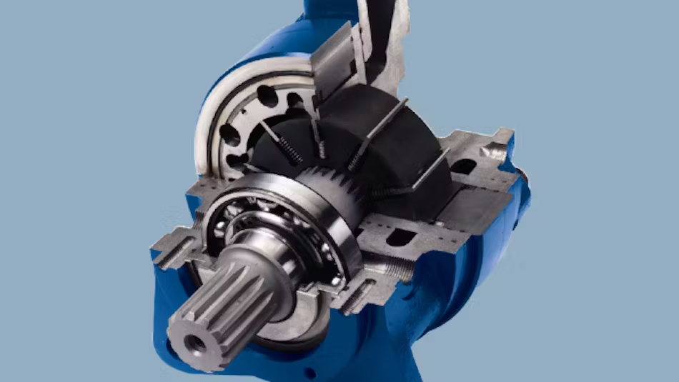
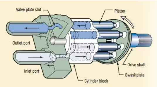
Axial piston (swashplate) motors: Typically optimized for medium to high speeds; they may struggle to maintain smooth motion at ultra low speeds unless specially designed for it.
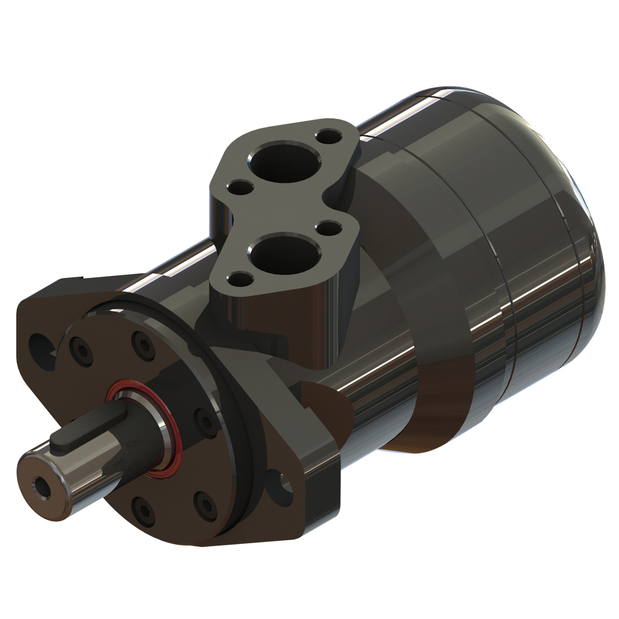
Orbital (gerotor/geroller) motors: These low-speed high-torque (LSHT) motors have a natural advantage in the low-speed range due to their internal cycloidal mechanism. Their design inherently smooths output at low RPM, especially in large displacement models.
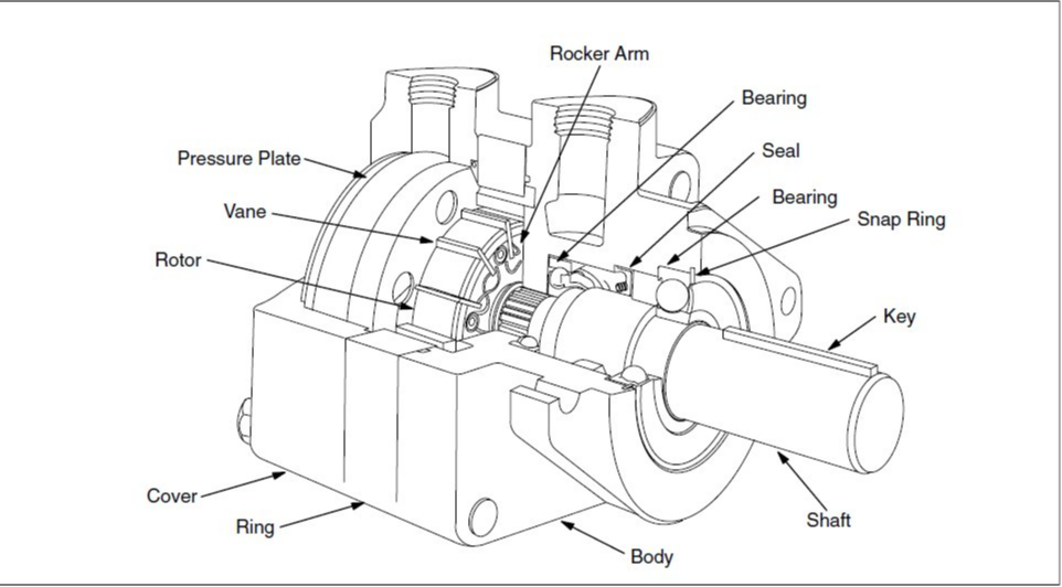
Radial piston motors: With multiple pistons arranged radially (often called “star” motors), these can achieve extremely low speeds. Having many pistons working in sequence smooths out the torque ripple significantly, making creep-level speeds possible.
Inner-curve (cam lobe) motors with rolling elements (e.g. steel ball or roller motors): These motors are specifically built for very low speed, high torque operation. They use multiple cams and rolling elements (balls or rollers) to generate continuous torque with minimal ripple, at the cost of requiring very high precision in manufacturing.
Which Motors Can Truly Achieve <50 RPM?
Only a handful of hydraulic motor types can reliably operate in the range of a few dozen down to single-digit RPM with smooth, continuous motion. The main categories include:
Orbital Motors (Gerotor/Geroller motors): These are the common choice in low-speed, high-torque applications. Orbital motors (also known as cycloid or “orbiter” motors) have an internal ring gear and rotor set that creates multiple chambers. This structure gives them a natural advantage for low-speed operation – essentially, their output is already slow and high-torque by design, and increasing the displacement further lowers the achievable speed. In practice, the larger the displacement, the more stable the motor can run at very low RPM. For example, a model like the OMER-300 (300 cc/rev displacement) can run stably at around 15 rpm. Many orbital motors in the 400+ cc/rev range are capable of maintaining steady rotation in the 30–50 rpm range or above with minimal judder. In fact, manufacturers often specify a minimum speed for orbital motors; for instance, a Danfoss OMR 125 (125 cc) has a referenced minimum stable speed of about 9 rpm (corresponding to roughly 1.2 L/min flow). This shows that well-designed gerotor motors can approach single-digit RPM under the right conditions, though below their stated minimum they may exhibit “speed ripple” or intermittent motion.
Radial Piston Motors: These could be considered the kings of ultra-low speed in hydraulics. A radial piston motor has multiple pistons arranged around a cam, often with several pistons pushing per cycle. With enough pistons (and thus a high number of torque impulses per revolution), the output torque ripple can be made extremely small, allowing the motor to turn very slowly without jerking. Large-displacement radial piston motors (for example, certain “outer star” radial designs) can run steadily at ~10 rpm, and with specialized valve manifolds or servo controls, they can achieve 5 rpm or even lower while remaining smooth. This performance does come at a cost – such solutions are expensive and typically used only in high-end equipment or applications with strict requirements. The low-speed prowess of radial piston motors is well documented: they are categorized as low-speed high-torque motors and often exhibit stable operation below 10 rpm; indeed, some multi-piston radial designs can run as slow as 0.5 rpm under load. Parker’s catalog of LSHT motors even spans speeds from 0.5 rpm up to thousands of rpm, indicating the availability of motors tailored for sub-1 RPM operation. In summary, radial piston motors (including variants like the Staffa, Poclain, or Hägglunds drives) are among the few that can achieve crawl speeds (on the order of 1 rpm) in a controlled and continuous manner.
Steel Ball Motors (Inner-Curve Ball Piston Motors): Often referenced in China as “QJM” series or inner-curve motors, these are a type of radial design where steel balls act as the rolling pistons against an inner cam ring. They are inherently suited for low-speed, high-torque output. For example, models in the 1QJM-32 series and above are known to run stably at around 10 rpm continuous. Steel ball motors combine large displacement with multiple contact points (balls) to provide smooth torque. However, they depend on extremely high machining precision and proper assembly – any slight error can introduce vibration at low speeds. When selecting such a motor, it’s crucial to inform the manufacturer of the ultra-low speed requirement so that they can ensure the motor is built and tuned for that operating range. In practice, a well-built inner-curve ball motor can rival other radial piston motors in low-speed performance, but quality and precision are paramount.
A Workaround: Throttling the Return Line to Slow a Motor
In real-world engineering, there is a “quick fix” some people attempt for achieving slower motor speeds: using a one-way throttle (flow restrictor) on the motor’s return line to create a bit of back-pressure. The idea is that by adding resistance to the outlet flow, the motor sees a controlled load that can help smooth out low-speed operation and prevent it from free-wheeling or jerking too easily. This added back-pressure can indeed make a motor less prone to lurching at low flow, effectively forcing it to move more steadily within a certain low-speed range.
However, this method comes with significant downsides:
It increases back-pressure in the system, meaning the motor and entire hydraulic circuit operate under a higher baseline pressure. This wasted pressure translates into energy loss as heat. In other words, throttling the return sacrifices efficiency – the hydraulic pump must work harder (using more energy) to push fluid through the restriction, and much of that energy is dissipated as heat in the fluid.
Elevated back-pressure can exacerbate internal leakage in the motor. Since the return line pressure is higher, the pressure differential across internal seals is reduced, potentially causing more fluid to slip through clearances instead of contributing to output torque. This can further degrade low-speed performance and efficiency.
It can damage the motor’s shaft seals if taken to an extreme. Standard hydraulic motor lip seals are not designed to withstand full system pressure – they are usually only meant to hold the motor’s internal case drain pressure (which is much lower). By throttling the return without a proper case drain, you risk building up high pressure at the motor’s outlet and in its casing. This can blow out the shaft seal, causing leaks and motor failure. (Common mistakes like closing a return line or having an undersized/blocked return can similarly cause catastrophic seal failure, as the trapped pressure forces oil past the seals.)
Additional side effects include increased heat load on the oil (overheating) and possibly shorter component life due to the continuous extra stress and higher pressure on parts. The higher operating pressure can accelerate wear on bearings, seals, and other components over time.
In summary, using a return-line throttle is at best a band-aid solution to help an inadequately designed motor run a bit more smoothly at low speed. It should only be a last resort. It is not a true substitute for a proper low-speed motor and should not be viewed as such. The correct approach to achieve ultra-low speed is to use a motor inherently designed for that purpose, rather than forcing a standard motor into a regime it isn’t comfortable in.
Key Points for Using Low-Speed Hydraulic Motors
Whether in mobile machinery or industrial equipment, whenever low-speed operation is involved, keep the following principles in mind:
Avoid high load torque at ultra-low speeds – Do not demand excessive torque output when the motor is turning very slowly. The lower the speed, the more difficult it is for the motor to maintain smooth motion under high load. If you push for high pressure (torque) at crawling speeds, the motor is more likely to become unstable or stall. In fact, most motors exhibit a lower starting torque at very low speed than their nominal torque at higher speed. Always check the motor’s starting torque specs and don’t expect full-rated torque at a near-standstill; oversize the motor if necessary to provide a torque safety margin.
Ensure the flow supply is continuous and stable – At low speed, any fluctuation in flow will directly translate into a fluctuation in rotational speed. Each tiny pulse or drop in flow will show up as a shudder or jerk in the motor’s motion. To achieve steady low-speed rotation, the hydraulic pump and valves should provide the smoothest possible flow. This might involve using high-quality proportional or servo valves, accumulators to dampen pulsation, and avoiding sources of flow ripple. Essentially, a low-speed motor is only as good as the stability of the oil feeding it. If the system flow pulsates or drifts, the motor will mirror those disturbances as uneven output.
Control the oil temperature and viscosity – Oil temperature management is much more critical at low speeds. When oil gets hot, its viscosity drops. Thin (low-viscosity) oil will leak through internal clearances more readily, increasing internal leakage and reducing the motor’s effective output torque. This makes it even harder for the motor to maintain slow rotation, as more of the flow “slips” internally instead of moving the shaft. To combat this, keep the hydraulic oil within its optimal temperature range (via coolers or proper reservoir sizing) so that viscosity remains sufficient to seal clearances. A cooler, more viscous fluid will improve low-speed performance by reducing leakage and providing a better oil film for lubrication, thereby also reducing friction.
Recognize the no-load vs. load difference – It’s relatively easy for a motor to turn at extremely low speed with little to no load (since only internal friction must be overcome). In fact, many hydraulic motors can be made to creep along at 1 RPM or even slower with an open output shaft. However, doing the same under load is exponentially more difficult. The moment you put a real load torque on the motor, the ultra-low-speed performance can degrade drastically – what turned smoothly at 1 rpm with no load might stall or jerk with even a moderate load. Therefore, always evaluate low-speed capability under the expected load conditions. The minimum stable speed of a motor is usually specified at a certain load or pressure; running under no-load doesn’t truly test the motor’s low-speed stability in a working scenario. Don’t be misled by an unloaded test – ensure your motor (and hydraulic circuit) can handle the low-speed operation under actual working load.
Conclusion: Low Speed is a Systemic Challenge, Not Just a Number
Many people assume that achieving low speeds with a hydraulic motor is just a matter of “throttling the flow a bit more.” In reality, true low-speed performance is the result of a confluence of factors: motor structural design, fluid dynamics, friction characteristics, sealing precision, and the stability of the control system all act together to determine if a motor can run slowly in a stable, controlled way.
Thus, only a few types of hydraulic motors – notably orbital motors, radial piston motors, and inner-curve (steel ball/roller) motors – possess the inherent design features to deliver genuinely smooth operation at very low rotational speeds. Each of these comes with trade-offs (such as size, cost, or complexity) that must be considered. When selecting a motor for low-speed duty, one must look beyond the desired RPM and consider the entire system: the pump, valves, fluid quality, temperature control, and load conditions are all integral to success.
At the end of the day, the essence of a “low-speed motor” isn’t just that it can turn slowly – it’s whether it can maintain continuous, stable, and judder-free rotation at low speed**. Keeping this in mind will help in both choosing the right motor and configuring the hydraulic system to meet the challenge of ultra-low-speed operation. With careful design and the right components, hydraulic motors can indeed crawl at astonishingly low speeds, all while delivering the high torque that their technology promises.


