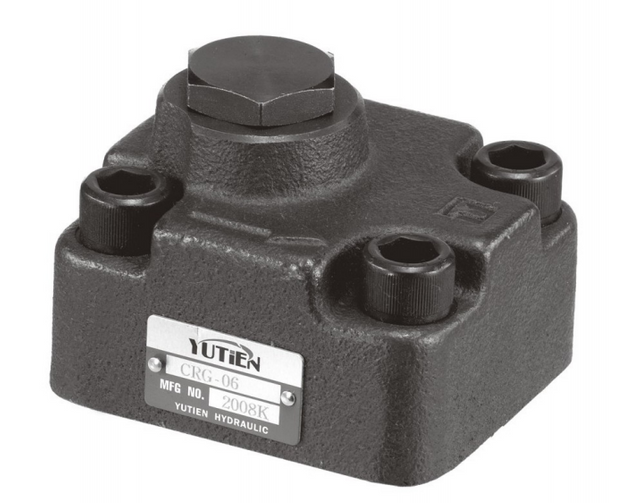
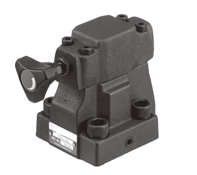
Use a two-way hydraulic flow control valve when you need to meter one branch and the circuit already has a way to handle unused pump flow. Consider a three-way priority regulator when one branch needs flow first and the excess has an approved route. Before ordering, check the pump type, the pressure at each outlet, and what happens to surplus oil when the controlled branch slows or stops.
Start with one operating state and draw the oil paths
Picture a small hydraulic motor that needs 12 L/min on a machine with 30 L/min available at the proposed valve inlet. The motor is only one part of the decision. The other 18 L/min has to go somewhere when that inlet flow is actually present. It might be supplied to a second function through an approved excess-flow path, go back to tank, or be avoided if the pump reduces delivery. Some existing circuits send it through a relief valve. That choice affects supply pressure, power loss and how much oil is left for the machine’s other functions.
Find the circuit drawing and mark four points: the source of oil, the proposed flow valve inlet, the controlled outlet and the destination of unused flow. If the source already shares oil with another function, mark where the branches split. A pump nameplate gives a starting point, but the valve inlet flow at a given machine speed can be lower than pump capacity. A branch downstream of another valve can also see a very different pressure and flow from the pump outlet.
Define which operating condition matters first. A conveyor may need a steady speed during production, then a different adjustment while operators clear material. A feed device may operate alone or with a clamp. A test that describes only the running motor misses what happens when the motor is stopped and the pump keeps turning. Draw the path in both conditions. Then add any relevant transition, such as a second function beginning to move while the motor is running.
Start the comparison with two real numbers if the machine has them: flow available at the proposed inlet and the flow required by the controlled function. Include oil temperature and the pump or engine speed for those readings. A flow figure taken at rated engine speed will make the setup look more capable than it is if the function actually runs at idle. A rate read at the reservoir return can include oil from several branches. Give those readings separate labels in the inquiry.
The BLINCE hydraulic flow control valve guide explains how adjusting a passage controls flow. For the choice between two and three ways, carry that idea one step further. Look at the complete supply and return circuit while the actuator is moving and while it is idle. The extra port is useful only when its destination makes sense in both states.
What do the controlled and excess ports do?
Names vary between manufacturers. Here, a two-way flow regulator means a unit with inlet and outlet in the controlled path. A three-way priority regulator has an inlet, a controlled outlet and another outlet for excess flow. Catalogues may label the latter two CF and EX. Other labels are possible, so use the drawing that belongs to the exact order code. A valve with three visible connections could have a pilot or drain port instead of a usable excess outlet.
Pressure compensation helps regulate flow as the pressure at the load changes. It relies on a compensating element maintaining a suitable pressure drop across a metering opening over the design’s operating range. The valve needs sufficient upstream pressure above downstream pressure to work as intended. If the pump cannot supply the required flow or pressure margin, the compensated setting cannot make up for it. This is why the catalogue curve matters more than the wording on the knob.
There is a useful distinction between the pressure required for the actuator and the pressure needed to operate the valve. Suppose a motor branch needs 100 bar at the inlet under one condition. The flow valve and intervening lines add loss. A pressure at the supply equal to the unadjusted motor requirement gives the regulator little or no room to maintain its flow. Ask the vendor to identify the minimum differential needed at your flow and the test conditions used to obtain the curve.
A regulator may have a forward direction and a specified reverse-flow behavior. A check valve option can provide a reverse path in some designs. Other cartridges block, restrict or behave differently when the flow direction changes. Confirm that feature where the application reverses, coasts or is driven by a load. A valve intended to control speed in one direction does not by itself control how a suspended or overhauling load moves.
In one documented example, the HydraForce FR10-33 technical page specifies both priority and an approved restrictive configuration. The regulator has different published flow limits under the two configurations. This is a useful example of how to read one data sheet. It does not establish that another valve can be converted in the same way. When specifying a replacement, confirm the symbol, permitted plumbing and limits for that part number and body.
When a two-way flow regulator fits
A two-way hydraulic flow control valve is a good candidate when the job is to meter one branch and the machine already has an appropriate way to manage flow not used by that branch. That could be pump displacement control, a designed unloading path, or an existing manifold architecture that distributes flow before the regulator. Check how the circuit behaves when the branch speed is lowered and when its directional valve closes.
In a load-sensing circuit the pump can, within its design, reduce output when demand falls. The useful question is whether the proposed valve belongs in that control arrangement. If a change affects the load-sense signal or its pressure margin, the response can change for other functions too. A pump being variable displacement does not by itself prove that it will reduce flow exactly as the branch setting changes. A pressure-compensated pump and a load-sensing pump should be reviewed against their actual control schemes.
With a fixed-displacement pump, the amount delivered generally changes with drive speed and operating conditions. A restriction in one branch does not ask the pump to deliver less. If that branch is the main path and there is no suitable alternative for the surplus, pressure may rise until an existing protection or bypass path takes flow. A relief valve should be understood in its designed role. Continuous relief flow at elevated pressure is a significant energy cost and may make the low-speed operating condition the hot condition.
If a replacement catalogue says “2-way pressure compensated,” check whether the measured branch is the supply to the actuator or its outlet. Meter-in means controlling flow entering the actuator; meter-out means controlling flow leaving it. Their suitability depends on the load and circuit. Metering cylinder exhaust can involve a different flow rate from the supply rate because the two piston faces differ in area. For a motor, note the direction, loading and any return or case limits that matter. A matching nominal flow setting does not resolve any of those conditions.
One purchasing example is a branch that already has a suitable reduced flow supply and needs a small adjustment range for one motor. Ask whether the two-way regulator remains within its useful range at the lowest intended running speed. A device that handles the high end comfortably can be difficult to set near the bottom of its range. If a product sheet gives a flow-versus-adjustment curve or different spring options, use the relevant option instead of choosing the biggest nominal flow.
When a three-way priority regulator fits
A three-way hydraulic priority flow control valve is a candidate when one function needs a defined flow first and surplus oil has a supported second destination. Normally the circuit offers controlled flow to the priority branch when enough inlet flow is available. Excess sent to tank passes through the designed return route. Excess supplied to another function depends on the exact valve’s permissible outlet pressure, the circuit arrangement and available flow and pressure on that branch.
Start by listing the minimum required priority flow, maximum expected inlet flow and the pressure at the controlled and excess outlets when both functions operate. The Bosch Rexroth three-way flow-control data sheet shows a model with a pressure-compensated priority outlet and a separate bypass outlet that can supply other machine functions. That example has its own relief, drain and pressure limits. Ask for the symbol and permitted pressure for each port on the exact assembly being quoted.
A simple budget helps avoid the common mistake of choosing a valve only by its priority setting. If the priority branch needs 12 L/min but the proposed inlet can see 42 L/min, the valve still has to handle the inlet and the path for the other 30 L/min. Read the inlet capacity and excess-flow capacity separately. Ask what happens at minimum pump speed too. There may be little or no excess left for the second function whenever the priority circuit takes most of the supply.
If the excess outlet returns to tank, include the expected back pressure from downstream lines, port restrictions, filters and the rest of the return circuit. If it supplies another actuator, include that actuator’s demand and pressure under coincident load. An excess outlet connected to a working branch can operate under pressure only within the specific circuit and valve limits. Even a valve whose excess port accepts pressure can have different behavior across flow, pressure and temperature.
Look at stopped and abnormal states as well as normal operation. The priority branch may be blocked when a directional valve shifts to neutral. In another circuit the branch takes oil even though the motor is mechanically stopped. Check the documented behavior of the chosen regulator under that condition. Manufacturer instructions differ on which ports may be obstructed and what happens to the other outlet. Leave the permitted route to the engineering review and the exact schematic. An unverified plugged port is a design issue to resolve before purchase.
A flow budget for four machine states
The following numbers are hypothetical. They show the checks a reviewer can apply when the regulator is in range. They do not assign a rating to any valve.
Machine state
Flow actually arriving at the inlet
Controlled-flow target
Remaining flow in the nominal budget
Purchase question
Slow drive speed
10 L/min
12 L/min
No surplus in the ideal balance. Actual controlled flow is at most 10 L/min
Can the machine accept the resulting slower speed?
Normal run, one function
30 L/min
12 L/min
18 L/min
What approved route takes the remainder?
Normal run, second function active
30 L/min
12 L/min
Up to 18 L/min before circuit effects
What outlet pressure and flow are required simultaneously?
High drive speed
42 L/min
12 L/min
Up to 30 L/min
Are the inlet, excess branch and return components rated for this state?
The arithmetic treats the flows as a steady balance and ignores leakage. Actual regulator performance depends on pressure margin, permitted outlet conditions and its published curve. The comparison exposes a useful split in the specification: the regulated setting describes the priority branch, while the inlet and bypass figures describe the rest of the flow the body may have to pass.
Add a separate line for stopped operation. On some machines, oil available at the valve disappears when the main directional valve returns to neutral. On others the branch remains supplied. Record the state of the main pump, every relevant directional valve and the next function in the sequence. A reviewer needs this row even though the priority target is zero or undefined. The stopped state can determine both return flow and the protection arrangement.
Compare pressure loss with the same flow and duty
Pressure difference across a flowing restriction represents hydraulic power being dissipated there. Estimate the hydraulic loss across a steady, non-working branch by multiplying its flow in L/min by its pressure drop in bar, then dividing by 600 to obtain kW. The factor converts bar to pascals and litres per minute to cubic metres per second, then watts to kilowatts. Use the flow and the two pressures from that same path at the same time. The estimate is useful for a first comparison of losses, while total system heat also depends on pumps, actuators and other parts of the circuit.
Consider two hypothetical readings on a surplus path that carries 18 L/min. In the first example the assumed pressure drop between the two taps is 140 bar. The dissipation estimate is 18 × 140 ÷ 600 = 4.2 kW. If another approved circuit operates at 20 bar across its corresponding surplus path, the same flow gives 18 × 20 ÷ 600 = 0.60 kW. These are separate assumed conditions, not a prediction that changing one valve automatically creates the second condition.
Hypothetical surplus path
Flow
Pressure difference across that path
Estimated hydraulic loss
High differential
18 L/min
140 bar
4.20 kW
Lower differential
18 L/min
20 bar
0.60 kW
The branch pressure difference is central. Suppose the inlet of a priority regulator reaches a high pressure because the controlled motor is working hard. The excess outlet may still discharge to a low-pressure destination. A large difference across the excess path can remain even though the oil returns to tank. A three-way valve separates flow destinations, but the pump and the loads determine the pressures that make the energy calculation work.
The flow-control element in the controlled branch also has a pressure drop when it meters. That loss needs its own line in the review. A motor doing useful shaft work should be evaluated separately from a valve dissipating energy to regulate flow. If the surplus feeds a productive load, the full pressure difference from pump to tank includes work by that second actuator. Use measurement points that isolate the loss you intend to estimate. Counting all pump power as valve heat can obscure the reason one design runs warmer.
If the duty alternates between long periods at low controlled speed and brief higher-flow periods, record the durations. A large power loss for two seconds and the same loss for ten minutes are different cooling problems. A time-weighted calculation can help frame the average, but it does not establish peak pressure or local temperature limits. Include both the normal heat-producing condition and any short event that drives pressure or flow to its limit.
What a pressure reading can leave out
A single pump outlet gauge can show a high number while the regulator inlet sees less, especially if a manifold, selector valve or line lies between them. Likewise a gauge near the tank will miss pressure at an excess outlet upstream of a restrictive return element. Mark intended measurement points on the drawing. Use the machine’s approved test procedure and have the observations taken by a qualified technician. If the required measurement is missing, state which pressure or flow is unknown rather than treating the catalogue setting as a recorded test.
On a repeatable machine cycle, compare readings while the first function runs alone and when the second function overlaps. Record the flow setting commanded, the oil temperature, the loads and the supply speed. This makes it possible to see whether the priority speed is affected when downstream pressure changes or when the pump simply cannot supply the total demand. The two problems can look similar from the operator’s seat, but the purchase decision is different.
Check the offered valve against the machine drawing
Send the supplier a marked schematic or a clear excerpt from it. Show whether the pump is fixed, pressure compensated or load sensing, and identify where the flow valve sits. Add the measured or estimated inlet flow range, desired adjustment range and port pressures. Distinguish actual measurements from programme targets and design estimates. The reviewer can then look for a specific valve and body combination, rather than guess from the thread size on the old unit.
For an inline valve, compare mounting envelope, port orientation, thread and sealing details, and how the adjustment will be accessed. For a cartridge, check the cavity, seal material, body pressure rating and port assignments. A cartridge that threads into a cavity can still require a different flow order or perform a different function. When the old part has a different integral check valve or relief feature, include its operating diagram so the vendor can show how the proposed circuit reproduces the required function.
Ask the supplier to mark the flow curves it used. Request the regulated range, usable inlet range and operating pressure limits at each port, plus minimum pressure margin when the controlled branch is loaded. Confirm permitted reverse flow, behavior if a branch is blocked, and the conditions for any relief or check option. If the supplier offers a configurable device, request the actual option and ordering code selected for the drawing. Where the vendor offers both a tank-return and a loaded-outlet arrangement, ask for the evidence for the one on your drawing. A maximum port-pressure figure gives a limit. A flow-versus-pressure curve or a test at two agreed loads can show how much the controlled flow actually changes. Compare those figures with the amount of speed variation the machine can accept.
A useful inquiry also describes what the operator should observe when two functions move together. For instance, the motor might have to keep a consistent speed while a small cylinder completes its full stroke. Put the target speed and acceptable slowdown in the request, along with the oil flow and pressure known for that test. If priority really means “the motor must keep moving while the other function can wait,” say so. This establishes what tradeoff the circuit is allowed to make.
Quote field
What to attach or specify
What to check in the reply
Pump and supply
Pump type, delivery range at operating speeds and control schematic
That the proposed layout can manage flow when the actuator slows or stops
Controlled branch
Required flow range, working pressure and direction
Regulator operating range and required pressure margin
Excess branch
Tank or second function, expected flow and pressure
Port capability and behavior under combined load
Physical build
Old tag, body/cavity, connections, mounting and seals
Exact part code and drawing
Acceptance condition
Warm oil, slow and high supply speeds, intended overlapping functions
Documented response or a test plan for conditions that remain unverified
Use the BLINCE flow control valve category when looking for a commercial starting point. Confirm an exact schematic and part before purchasing. The category alone cannot establish that a particular three-port configuration or reverse-flow option is offered. If you are replacing a regulator after a speed complaint, include the existing symbol and the operating state where speed varies. The supplier can review the original circuit and the proposed valve against the same measurements.
How to compare two valve quotations
Put two quotations on the same circuit drawing. Ask each supplier to show the exact assembly code and port symbol, the applicable flow curve at your branch pressure, and the path for unused oil when the controlled function slows or stops. Use the same inlet-flow range and load assumptions on both replies.
If a second function receives surplus flow, define what that function must still do while the priority actuator runs. A feed motor could require a stable speed while a cylinder needs to finish its stroke. List the acceptable motor speed change and the minimum cylinder flow. Ask the valve manufacturer or supplier which operating points its curves cover, and request the exact body, cartridge or assembly code. The expected response under simultaneous load gives you a better basis for comparing quotes than a single maximum flow value.
For a direct replacement, place each proposed drawing next to the existing port diagram. Check inlet and controlled outlet first, then the excess and reverse paths, pressure limits and cavity or mounting. If a feature is different, ask what it changes in the circuit and what must be verified before placing the order.
Questions buyers ask about two- and three-way valves
Can I use the excess port as a second pressure outlet?
Some priority regulators allow a pressurized excess outlet within documented limits. Check the exact valve, the pressure required by the second function and how it behaves when both branches work at once. A return-only outlet or an integral relief arrangement can impose a different limit. Ask for the port diagram with the quote.
Will a three-way valve run cooler than a two-way valve?
It depends on the pressure drop and duration of flow on each path. Compare both circuits at the same actuator duty. A three-way arrangement can provide an approved surplus path, while its loss may remain significant when the pump operates at high pressure. Calculate branch losses using the actual pressure difference and flow.
Is pressure compensation enough to keep the actuator speed constant?
Pressure compensation helps keep regulated flow within the design range when pressures vary. The pump still needs to provide enough oil and pressure margin. The actuator’s own leakage, load and reversing circuit can also change the speed. Confirm the needed accuracy at the warm and cold conditions relevant to the machine.
Send the circuit and three operating points for an initial review
Provide the pump type and proposed valve position, then give the intended flow, pressure and required behavior at low supply speed, normal operation and when both functions run together. Show where surplus oil should go and how the machine behaves with the controlled function stopped. Include the old valve code if the request is for replacement.
When you contact BLINCE about the valve, ask for the exact circuit symbol, order code and relevant flow data. Request a marked view of the inlet, controlled outlet and any excess or reverse path. Use that response to identify the operating conditions still to verify before selecting the part.
This article is a general engineering guide. Final component selection should be based on machine drawings, measured hydraulic data, working conditions, safety requirements, and confirmation from a qualified hydraulic engineer or supplier.
Blince Hydraulic Team
Blince Hydraulic is an industry-leading company dedicated to precision-engineered fluid power manufacturing and custom hydraulic solutions. Backed by decades of deep field expertise in industrial machinery and thousands of successful global deployments, our engineering team focuses entirely on high-performance hydraulic component manufacturing, including specialized orbital motors, high-pressure travel drives motor, and robust directional control valves. Our production infrastructure utilizes state-of-the-art multi-axis CNC machining systems and is fully ISO 9001 certified to guarantee repeatable volumetric accuracy across every single manufacturing run.
We deliver fast, highly dependable, and cost-efficient hydraulic solutions to heavy industry distributors, machinery OEMs, and maintenance crews across more than 150 countries. Whether your active project calls for a small-volume batch of customized shaft profiles or a large-scale production run of severe-duty cast iron gear pump, we configure our flexible production schedules to meet your target lead times with total pricing predictability. Partnering with Blince means securing maximum system efficiency, elite material quality, and uncompromised fluid power professionalism.
To learn more about our complete product lineup, visit our official website: www.blince.com.