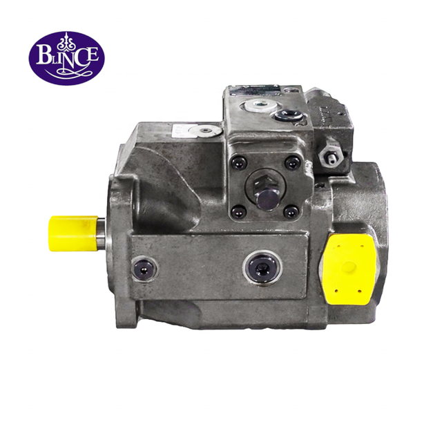
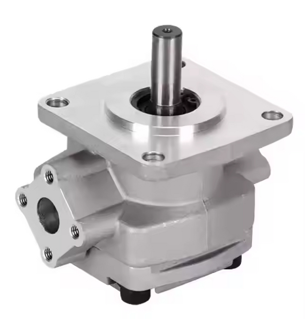
One function has slowed down, but the other function supplied by the same double vane pump still works. Replacing the apparently weak cartridge seems an economical answer. Before ordering it, establish what “low flow” means: less oil leaving that pump section, less oil reaching its actuator, or simply a smaller output than the other section was designed to produce.
Short answer
Diagnose one low-flow section by identifying both displacements, recording loaded shaft speed, and comparing flow at known measurement points under documented pressure and oil-temperature conditions. A healthy-looking second function does not prove the common inlet or drive is healthy. Low actuator flow does not prove low pump delivery. Use the evidence to choose a branch-circuit check, a controlled pump test or a repair assessment.
Write down the unequal behavior before interpreting it
Start with the machine's behavior, not a proposed failed part. Record which movement became slower, whether force is also reduced, whether the fault appeared after service, and whether the other function is genuinely unchanged. A small timing change in a lightly loaded circuit may go unnoticed while a heavily loaded movement misses its production target. The tandem-pump circuit guide helps identify what each section supplies, while pressure test-point planning separates a pump-outlet reading from a measurement farther downstream. Describe the state in which the complaint occurs; “one side is weak” is not yet a test result.
A symptom that began immediately after cartridge work deserves a different first investigation from one that developed over many operating hours. In the first case, check identity, connections and the service record before attributing the problem to progressive wear. In the second, compare current measurements with the earlier operating baseline, including temperature and load. The vane-pump noise and flow-loss discussion supplies useful symptom distinctions, and the contamination-control guide helps interpret recent oil, hose or filter work. Neither timing pattern proves one cause, but each changes the evidence worth collecting before opening a pump.
Avoid calling the second section “good” solely because its actuator moves. Its circuit may operate at lower pressure, use less than the available delivery, or tolerate a longer cycle. Establish what normal meant for that function: speed, pressure, oil temperature and simultaneous machine actions. The pump-flow explanation makes that performance boundary explicit; the oil viscosity guide explains why a warm reading cannot be compared casually with an earlier cold one. An observed difference between functions is a clue. A comparable difference between measured operating points is much stronger evidence for a repair decision.
Identify two sections, not just one pump family
BLINCE's PV2R12, PV2R13 and PV2R23 page describes two pumping units driven by one shaft, with a common inlet and separate outlets. The SQP double-vane page likewise identifies shaft-end and cover-end displacement codes. Those facts matter because the two sections need not have equal displacement. Photograph the complete assembly code and mark each outlet on the circuit drawing before comparing litres per minute. A family name on a purchasing message does not identify which cartridge serves the slow function or establish the geometric displacement used in a calculation.
Check whether the machine actually uses independent circuits, combines the outlets during part of its cycle, or unloads one section intentionally. A low reading after an unloading valve can be expected even while the pump section itself supplies substantial flow. The double-pump selection discussion distinguishes a double pump from a high-low supply arrangement, and the vane-pump category provides the broader product context. Identify the installed circuit rather than inferring it from the number of pump housings. The repair question changes completely if the apparently missing flow has a designed route back to the reservoir.
Published installation guidance also puts identification and supply conditions ahead of a loaded trial. Parker's HY29-0101/EU, English page 2 calls for checks of rotation, connections and fluid condition and warns against continuing an unsuccessful start. These are relevant principles, not interchangeable startup instructions for every manufacturer. The required rotation, speed, priming method, pressure limits and stopping conditions belong to the exact pump and machine documentation. This guide does not provide settings for an unknown assembly or authorize an improvised test circuit.
Locate the flow measurement boundary
A flowmeter in the actuator feed reports the oil reaching that location. It does not necessarily report all oil leaving the pump. Relief, unloading, priority, flushing or other branches may divert delivery upstream of the meter. Mark every connection between pump outlet and measurement point before calculating an efficiency. The pressure-gauge placement guide is useful for assigning the corresponding pressure boundary, while the tandem circuit reference helps trace separate or combined outlets. Without that sketch, a precise-looking low-flow number may send a serviceable pump to the repair bench.
For a section-delivery assessment, the test arrangement must account for the section's total outlet delivery and the conditions under which it is produced. The technician also needs the actual pump-shaft speed, not only the electric motor's nominal nameplate speed or the engine's commanded setting. The drive and coupling checks belong in that record, together with the displacement-to-flow relationship. A speed loss affects theoretical flow before any internal leakage is considered. Recording speed under load helps distinguish a pump-section problem from a common drive that slows when combined shaft demand rises.
The measuring equipment can alter the result. A meter, test manifold or restrictive adapter adds pressure drop, and its rated range, fluid compatibility and temperature capability must suit the approved procedure. Record the pressure at the pump side of that added resistance, the relevant downstream pressure and the instrument's accuracy. The pressure measurement reference explains why location matters, and the viscosity discussion identifies another condition that can change the reading. Do not interpret a small change as wear without considering repeatability, instrument uncertainty and whether the test itself changed the operating point.
Use a qualified technician and the machine manufacturer's test arrangement, load-control method and isolation procedure. Support hazardous loads, control stored pressure and keep people clear of possible motion. Do not cap a turning positive-displacement section, swap live hoses, defeat relief protection or use an actuator stop as an improvised pump test.
Worked example: the larger flow can be the worse result
Assume, only for this calculation, a double pump with section A at 20 cm³/rev and section B at 40 cm³/rev. Both turn at a measured 1,450 rpm. These values are hypothetical, not specifications for a selected BLINCE product. The SQP two-code arrangement illustrates why both sizes belong on the worksheet, and the general pump-flow method provides the calculation format. Before inserting a real code, confirm its geometric displacement: a designation or nominal flow code must not be treated automatically as cubic centimetres per revolution.
The theoretical delivery calculation follows swept volume per revolution multiplied by revolutions per minute. Parker's HY18-1000 pump-equation page, printed page 17 also distinguishes actual delivery from theoretical flow when defining volumetric efficiency. Here the ratio is used as a diagnostic worksheet value. It is not a universal acceptance limit, a measure of overall efficiency, or proof of where oil is lost. That interpretation depends on the measurement boundary and the applicable performance data.
Section B still supplies more litres per minute than section A, yet delivers a smaller fraction of its theoretical output. Comparing 40 with 26 alone would hide that distinction. Before interpreting the ratios, attach each section's pressure and the common oil temperature to the readings. The PV2R double-pump description establishes the independent-output arrangement, while pressure test-point guidance explains how different branch loads can produce different operating pressures. The ratios are not directly comparable pass/fail grades if the sections work under different loads, and even matching loads do not make unlike cartridges identical.
Now suppose the expected section-B delivery at the same speed, pressure, oil condition and measurement location is 52 L/min, based on a valid earlier test or an applicable manufacturer curve. That expected value is also hypothetical here. A current 40 L/min is then 12 L/min lower, or approximately 23.08% below that reference. The vane-pump flow-loss discussion helps organize possible causes, and contamination evidence can justify further inspection when the trend follows a damaging event. This comparison is more useful than declaring every pump below an arbitrary efficiency percentage defective.
Difference from comparable reference = 52 − 40 = 12 L/minRelative delivery reduction = 12 / 52 × 100 = 23.08%The reference must match the operating conditions.This is not a manufacturer's rejection threshold.
There is an important alternative interpretation. If 40 L/min was measured in the actuator branch, while total section-B pump delivery was actually 52 L/min, the missing 12 L/min may be leaving through another circuit path. The same arithmetic then points downstream instead of into the cartridge. The tandem circuit guide helps locate the split, and the cooling assessment becomes relevant if that stream crosses a substantial pressure drop. Do not call the branch-flow ratio pump volumetric efficiency. First account for the oil crossing the measurement boundary.
Separate a delivery fault from a distribution fault
When measured pump delivery remains consistent with the applicable reference but the actuator is slow, follow the supplied branch. Check the commanded valve state, any unloading or priority function, and the actual pressure relationships across the components that can divert or restrict flow. Use named pressure measurement points rather than treating one main gauge as the entire circuit, and review the system flow calculation before assuming a smaller actuator movement means lower pump output. The next decision is a circuit investigation, not an automatic cartridge order.
A relief path can conceal this distinction because the pump may develop pressure while useful actuator flow remains low. For an illustrative branch split of 12 L/min across a 160 bar pressure drop, the dissipated hydraulic power is about 3.2 kW. That value belongs to the assumed diverted stream, not the entire pump's losses. The oil-cooler guide can help frame the thermal consequence, while the viscosity reference keeps hot-operation comparisons consistent. A hot valve or pipe is a reason to investigate the route; surface temperature alone does not quantify the bypass or identify a failed component.
If the apparent fault changes when another machine function starts, record both functions and both section pressures at that event. The change may involve common drive loading, shared supply conditions or a valve interaction; it is not enough to conclude that one cartridge has failed. The combined shaft-load explanation and coupling inspection guidance are useful together here. A loaded event can lower shaft speed without being obvious from sound alone. Equally, unchanged speed does not clear every shared condition. The purpose of the simultaneous record is to narrow the next check, not to pick a culprit from one symptom.
Do not clear the common inlet just because one branch works
Both sections can share an inlet without experiencing identical operating demands. A larger-displacement section requires more inlet volume at the same speed, and the two outlet circuits may impose different loads. A common supply problem therefore does not have to produce equally obvious symptoms in both functions. Inspect the reservoir's return-to-suction arrangement and consider the vane-pump inlet and noise discussion when planning the next measurement. Verify the inlet condition against the exact pump limit under the complaint state. The unaffected function is supporting evidence, not a substitute for an inlet reading.
Document fluid level through the machine cycle, suction-line condition, accessible inlet connections and breather condition within the maintenance procedure. Recently changed hoses, strainers or oil deserve particular attention because they may have changed the supply without changing the pump. The contamination-control checklist helps preserve the service history, and the oil viscosity guide explains why an approved oil designation still needs a temperature context. Do not apply a generic vacuum, temperature or cleanliness threshold from another pump family. Use the limits for the assembly being assessed, including any restrictions associated with its displacement combination.
The oil arriving at the pump may also contain air returned from elsewhere. A foamy reservoir, a changing oil level or a poorly arranged return path can complicate a diagnosis that initially appears confined to one cartridge. The reservoir baffle guide describes the relevant separation principle, while the cooler and return-path discussion helps trace where heated oil comes back. These observations do not prove aeration is the cause of the flow deficit. They identify system conditions that should be documented before a replacement is exposed to the same supply environment.
Use paired operating states to narrow the investigation
A useful comparison holds as many conditions constant as the approved procedure allows. Compare a section with its own valid reference at the same speed, pressure and temperature, then investigate how its delivery changes across permitted load states. Record the other section's state each time. The pump-flow guide provides the expected speed relationship, and the tandem-pump reference explains why both sections contribute to the common drive demand. This avoids a common false comparison: a low-pressure reading from one test placed beside a high-pressure reading from another, with the difference attributed entirely to wear.
A stronger hot-state deficit can be consistent with leakage across worn clearances, but temperature-dependent behavior does not uniquely identify a worn cartridge. Valve leakage and other circuit conditions can change too. The vane-pump troubleshooting article develops that distinction, while pressure measurements at the suspected boundary help determine where the changed behavior begins. If total pump delivery has not been separated from bypass, stop short of naming internal wear. If section delivery itself is below an applicable reference, the evidence supports further pump investigation, not a specific diagnosis of a vane, ring or side plate from outside the housing.
Instrument repeatability matters most near a proposed acceptance boundary. If two readings differ only slightly, the meter's uncertainty, temperature drift and speed change may be enough to explain the gap. Repeat measurements only within the approved procedure and preserve the original data rather than averaging away a changing condition. The viscosity guide helps identify one source of drift; drive verification addresses another. A clearly documented uncertain result is more useful than a precise percentage with unreliable inputs, especially when that percentage is being used to justify opening a serviceable assembly.
Choose the next action from the evidence
The decision table separates what the observation supports from what it does not yet prove. A product family such as SQP double vane pumps or the PV2R double-pump range identifies a route for technical review, but it does not supply an automatic rejection limit. Use the exact code and its documentation alongside the measurements. Where those records are missing, the next purchase may need to wait for identification or testing; changing both sections simply because they share a housing is not a diagnosis.
Observed evidence
Next direction
Benefit
Cost or remaining risk
Confirmation needed
Actuator flow is low; total pump delivery matches its reference
Investigate branch distribution, unloading or restriction
Avoids replacing a pump for a downstream problem
Several valve states may produce the same symptom
Marked circuit, simultaneous pressures and accounted branch flows
One section's total delivery is below a comparable reference
Arrange an approved pump test or controlled repair inspection
Focuses effort on a demonstrated delivery deficit
External conditions may still contribute; failed internal part is not identified
Exact code, performance reference, inlet condition, speed and temperature
Both sections change with combined load and shaft speed drops
Review drive capability and mechanical transmission
Addresses a shared limitation
More than one fault can coexist
Loaded speed, drive data, coupling condition and each section's pressure
One function appears normal but inlet or fluid evidence is abnormal
Correct and reassess the shared condition through the approved process
Protects a replacement from repeat exposure
Existing damage may remain after the system correction
Applicable inlet/fluid limits and repeat measurements
Cartridge damage is confirmed and the rest of the assembly is serviceable
Evaluate cartridge-level repair
May retain sound shared parts
Requires correct parts, cleanliness and validated assembly/testing
Inspection report, service dimensions, part identity and acceptance test
Shared parts are damaged, debris is widespread or identification is unreliable
Evaluate complete replacement plus system remediation
Resolves an unsuitable repair scope
Higher parts cost; a new pump still cannot fix dirty oil or incorrect plumbing
Full failure report, compatible replacement configuration and cleanup plan
Notice that none of the routes relies on matching the two outlet readings. The appropriate target is the expected behavior of each section in its own documented conditions. The flow calculation reference keeps that comparison proportional to displacement and speed; the contamination guide adds evidence that arithmetic cannot provide. Wear particles, damaged surfaces or a history of a previous component failure may change the repair scope even if one section still delivers acceptable flow. Numerical performance and physical condition answer related but different questions.
Decide how much to repair only after the failure boundary is known
A cartridge-level repair can be reasonable when the damaged section is positively identified, the other components are serviceable and approved replacement parts and procedures are available. It can also be a false economy if a shared shaft, bearing, housing or alignment problem remains. The pump coupling and mounting guide is relevant to those shared mechanical checks, while the SQP configuration page reminds the buyer that shaft-end and cover-end identities cannot be omitted. Ask for the inspection basis of a “cartridge only” recommendation rather than choosing it solely because its parts price is lower.
A complete pump can shorten some repair tasks, but it does not remove the cause of contaminated oil, poor supply or a misidentified circuit. Before introducing the replacement, establish what happened to any debris and which connected parts require inspection under the service plan. The filtration and contamination reference supports that discussion, and the vane-pump product category provides a starting point for the replacement inquiry. Do not use a successful no-load run as the only evidence that a contaminated or damaged system is ready to return to production.
Changing the displacement combination is a separate engineering decision. A different section may change actuator speed, inlet demand, drive loading, valve losses and heat, even if it fits the same basic housing. The PV2R two-section configuration should be matched by full code, and the tandem sizing guide should accompany any proposed change in output. Restoring the original verified duty is not the same task as increasing machine capacity. Keep those requests separate so that a repair quotation does not conceal an unreviewed performance modification.
Avoid tests that create a new fault
Swapping the two outlet hoses looks like a quick way to see whether the symptom follows the pump section. It may also connect the wrong displacement or pressure capability to a circuit, disrupt unloading or load holding, and alter the machine's intended sequence. Use the pressure-point planning guide to define an approved diagnostic boundary instead, and keep the two-outlet circuit explanation beside the schematic. A qualified test plan may use controlled reconfiguration, but this article does not authorize casual outlet swaps. The consequences depend on the complete machine, not just the pump.
A second shortcut is to raise pressure until the slow function appears stronger. Pressure capability and delivery are different quantities: a higher setting cannot establish where missing flow went. It can increase input demand and thermal stress while hiding the original observation. The vane-pump flow-loss discussion and cooler-sizing guide help keep those consequences visible. Preserve the original operating record and use the specified test procedure. A machine that temporarily moves better after an undocumented adjustment has not thereby demonstrated that its pump cartridge was the defective part.
Define the return-to-service comparison before approving the repair
Agree on the acceptance evidence before the pump is repaired or replaced. It should identify the correct assembly, the permitted test conditions, each section's delivery, the relevant pressures and temperatures, and the common drive speed. The vane-pump range can help organize the product identity, while measurement-point documentation prevents a post-repair branch reading from being compared with a pre-repair pump-outlet result. The acceptance target belongs to approved data and the machine's required performance, not the illustrative ratios in this article.
Record what changed as well as what improved. A replacement pump installed alongside a cleaned reservoir, new oil and a corrected valve setting does not isolate the effect of the pump replacement. That may be an appropriate repair package, but the history should say so. The contamination-control record and reservoir arrangement review help preserve those changes for future service. Retaining comparable evidence makes a repeat complaint easier to investigate and prevents an uncertain diagnosis from becoming an unquestioned purchasing rule.
Prepare a reviewable repair inquiry
Send the supplier a compact evidence pack before asking for “the weak half.” Include the assembly's complete identity and the measurement boundary, then explain whether the proposed job is restoring performance or changing output. The SQP configuration reference supports the first question, and the pump-flow calculation guide supports the second. A repair shop should be able to distinguish known measurements, calculated expectations and missing information without inferring them from photographs. That clarity helps compare cartridge repair, complete replacement and further testing on the same technical basis.
Identity: full pump code, nameplate, shaft-end/cover-end displacement codes, marked outlet photographs and rotation documentation.
Operating state: each section's pressure and flow, shaft speed, oil temperature, function commanded and whether the other circuit is loaded.
Measurement boundary: meter and gauge locations, circuit branches between pump and meter, instrument range/accuracy and test method.
History: onset, recent cartridge or hose work, oil/filter changes, prior comparable results, noise, debris and leakage observations.
Repair scope: inspection findings, shared-part condition, replacement code, retained components, cleanup plan and agreed acceptance evidence.
FAQ
Does one normal function prove the double pump is healthy?
No. Its section may have a different displacement, pressure demand or available flow margin. It may also be affected by a shared problem without creating an obvious machine symptom. Record its actual operating point and use it as supporting evidence, while checking the common inlet and drive where the complaint warrants it.
Should both outlets deliver the same flow?
Only if their displacements, speed and relevant operating conditions support that expectation. Many double pumps deliberately combine different section sizes. Compare measured delivery with each section's theoretical output and applicable performance reference. A larger flow number can still represent a larger delivery deficit relative to that section's own expected output.
Is 69% delivery ratio proof that the cartridge is worn out?
No. The example's ratio is not a manufacturer limit. It depends on correct displacement, loaded speed and total outlet-flow measurement. A meter downstream of a bypass cannot establish pump volumetric efficiency. Even a confirmed pump-delivery deficit needs investigation of operating conditions and, where justified, inspection before assigning an internal failure.
Can I replace only the section with low flow?
Possibly, after the failure is confirmed and the shared components are found serviceable. Verify cartridge identity, approved service procedures and acceptance data. Contamination, shaft damage or housing problems may widen the scope. A low quotation for one cartridge is not evidence that the remaining pump and system are suitable for reuse.
Why does the slow function recover when the oil cools?
Temperature changes viscosity and can change leakage and inlet behavior. The affected path might be inside the pump or elsewhere in the circuit. Compare measurements at documented temperatures and loads, with the meter location identified. Recovery after cooling is useful evidence, but it does not uniquely identify worn vanes or a damaged cam ring.
Can low flow coexist with normal pressure?
Yes. A pump can build pressure while delivering less than the required useful flow, and a branch can divert oil away from an actuator while maintaining a pressure reading. Pressure and flow must be recorded together at meaningful locations. One normal gauge reading cannot certify the output of both sections.
Request the next decision, not just another pump
Send BLINCE the full double-pump code, a marked two-outlet circuit and the comparable pressure, flow, speed and temperature records. The initial review can identify missing data, distinguish a branch-flow complaint from a demonstrated section-delivery deficit, and define what must be confirmed before quoting a cartridge or complete replacement.
This article is a general engineering guide. Final component selection should be based on machine drawings, measured hydraulic data, working conditions, safety requirements, and confirmation from a qualified hydraulic engineer or supplier.
Blince Hydraulic Team
Blince Hydraulic is an industry-leading company dedicated to precision-engineered fluid power manufacturing and custom hydraulic solutions. Backed by decades of deep field expertise in industrial machinery and thousands of successful global deployments, our engineering team focuses entirely on high-performance hydraulic component manufacturing, including specialized orbital motors, high-pressure travel drives motor, and robust directional control valves. Our production infrastructure utilizes state-of-the-art multi-axis CNC machining systems and is fully ISO 9001 certified to guarantee repeatable volumetric accuracy across every single manufacturing run.
We deliver fast, highly dependable, and cost-efficient hydraulic solutions to heavy industry distributors, machinery OEMs, and maintenance crews across more than 150 countries. Whether your active project calls for a small-volume batch of customized shaft profiles or a large-scale production run of severe-duty cast iron gear pump, we configure our flexible production schedules to meet your target lead times with total pricing predictability. Partnering with Blince means securing maximum system efficiency, elite material quality, and uncompromised fluid power professionalism.
To learn more about our complete product lineup, visit our official website: www.blince.com.