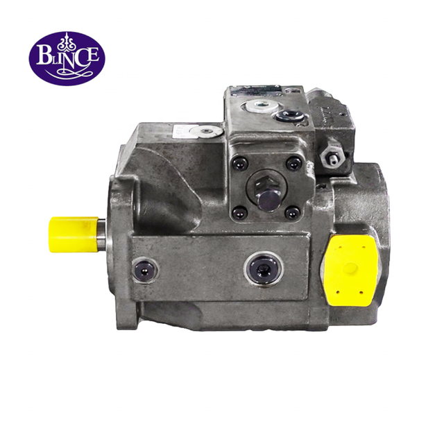
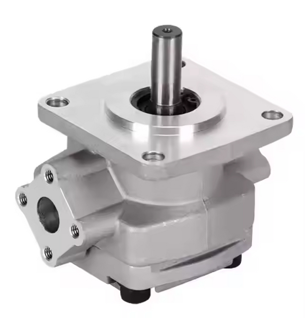
A replacement tandem pump can fit the flange, slide onto the shaft, and send oil from both outlets. The machine may still be wrong.
One section lifts the boom normally until the steering wheel is turned. A clamp circuit reaches pressure, but the conveyor loses speed at the same moment. The electric motor runs within its nameplate current during either function alone, then trips when both functions work together. On a cold morning, the rear pump section rattles for ten seconds while the front section sounds clean.
Those complaints are often treated as separate valve, motor, or cylinder faults. Sometimes they are. Sometimes the machine is revealing a more basic mismatch: the two pump sections were selected as individual pumps, while the shaft, inlet, prime mover, and return system must carry them as one assembly.
A hydraulic tandem pump is useful because one drive can supply two hydraulic circuits in a compact package. That convenience comes with a condition. Every operating state must be checked, including the moment when both sections see load at once.
The useful buying question is therefore not simply, "What is the displacement of each section?" It is:
Which functions can operate together, what pressure does each section see at that moment, and can the shared drive and inlet support the combined demand?
This guide develops that question into a practical selection and troubleshooting method for tandem hydraulic gear pumps, double vane pumps, and other multi-section fixed-displacement pump arrangements.
Why This Topic Causes Expensive Ordering Errors
The nameplate usually presents a neat model code. The machine does not operate as neatly.
A buyer may identify the shaft-end section as 35 cm3/rev and the cover-end section as 17 cm3/rev. Those numbers help establish flow, but they do not show which branch reaches high pressure, whether the functions overlap, how the common suction port is arranged, or how much torque passes through the coupling between pump sections.
The surrounding components matter too. A small hydraulic directional control valve may restrict the larger section. A return filter may be acceptable for one branch and overloaded when both return streams arrive together. A hose selected from its thread size may have too little internal area for the common inlet.
Blince supplies hydraulic pumps, motors, valves, cylinders, coolers, gauges, hoses, fittings, and related hydraulic system components. That wider view is important here because a double pump complaint often belongs to the circuit around the pump, not only to the pump cartridge.
Start With the Two Work Functions, Not the Old Pump Code
Before choosing a replacement, write down what each outlet actually does.
Does the shaft-end section feed steering, a clamp, a travel circuit, a cooling fan, or a pilot system? Does the cover-end section supply a large cylinder or continuous hydraulic motor? Can the operator use both functions at once? Does one section unload in neutral, or does it remain near relief pressure while the other circuit works?
The description should come from the machine, not from the catalog picture. A short field note might read:
The front section drives a conveyor motor continuously at about 95 bar. The rear section operates a clamp at 145 bar for six seconds per cycle. Motor current rises sharply when the clamp closes while the conveyor is running. Oil temperature reaches 68 C after forty minutes.
That note gives a supplier more useful information than "quote the same double pump." It identifies simultaneous duty, pressure, timing, heat, and the function most likely to expose insufficient drive power.
If the failure began after a hose replacement, valve change, new attachment, electric motor replacement, or reservoir repair, include that history. The complete hydraulic pump troubleshooting guide is relevant because a tandem pump can be blamed for a system change that altered inlet loss, drive speed, unloading, or return pressure.
What a Hydraulic Tandem Pump Actually Is
A hydraulic tandem pump contains two pumping sections driven in line by one input shaft. Depending on the product family, the sections may be gear, vane, piston, or a permitted combination. Each section has its own displacement and outlet. The inlet may be shared internally, provided through one common external port, or supplied through separate ports.
The sections rotate at the same shaft speed. They do not necessarily deliver the same flow because their displacements can differ. They also do not necessarily operate at the same pressure because each outlet responds to the load and valve logic in its own branch.
This arrangement is common where one machine needs two flow levels or two circuits without two separate prime movers. A tandem hydraulic gear pump may feed steering and implement functions on mobile equipment. A double vane pump may supply two machine-tool circuits where low noise and compact installation matter. A piston tandem arrangement may combine a main working circuit with a secondary function, subject to the manufacturer's through-drive limits.
Blince's SQP series double vane pumps illustrate the basic selection pattern: a shaft-end pump code, a cover-end pump code, shaft option, port orientation, mounting form, and rotation all belong to the full model. Leaving out one part of that code can change installation or performance.
Tandem Pump, Two-Stage Pump, and Double-Acting Vane Pump Are Not the Same Thing
These three terms are often mixed together in purchasing messages. They describe different ideas.
Term
What it describes
Typical purpose
Main selection question
Tandem or double pump
Two pump sections on one drive, usually with two outlets
Supply two circuits or two flow demands
What does each section supply, and when are both loaded?
Two-stage hydraulic pump
Two pumping sections combined through unloading logic
High flow at low pressure, then low flow at high pressure
At what pressure does the high-flow section unload?
Double-acting vane pump
One balanced vane cartridge with two inlet and two outlet zones per revolution
Reduce radial hydraulic load and provide smoother fixed flow
What cartridge, pressure, speed, and fluid conditions suit the application?
A tandem pump does not automatically switch from high flow to high pressure. If its two outlets are connected to independent circuits, each section continues to serve its own branch. If both outlets are combined, the circuit needs the correct check, relief, and unloading arrangement; a simple tee does not create a proper two-stage system.
For the high-flow/low-pressure and low-flow/high-pressure concept, see how a two-stage hydraulic pump works. For vane construction terminology, the article on single and double vane hydraulic pumps explains why "double acting" refers to one cartridge's pumping zones, not automatically to two pump sections.
Calculate the Flow From Each Section Separately
At a known shaft speed, the estimated delivered flow from each fixed-displacement section is:
Q = Vg x n x volumetric efficiency / 1000
Where:
Q is delivered flow in L/min.
Vg is section displacement in cm3/rev.
n is shaft speed in rev/min.
Volumetric efficiency accounts for internal leakage.
Suppose the shaft-end section is 32 cm3/rev and the cover-end section is 16 cm3/rev. At 1,450 rpm and an assumed volumetric efficiency of 0.90, the estimated flows are about 41.8 L/min and 20.9 L/min. The combined inlet demand is roughly 62.7 L/min before allowing for design margin and operating variation.
Do not use catalog displacement as proof of hot working flow. Volumetric efficiency changes with pressure, oil viscosity, wear, and pump design. A section that appears healthy during a cold no-load test may lose useful delivery after warm oil exposes internal clearance leakage.
When one branch is slow, measure that outlet instead of assuming both sections have worn equally. The article on a vane pump whining when hot shows why flow, inlet condition, temperature, and pressure should be recorded together.
Pressure Belongs to the Load, but Torque Belongs to the Shared Shaft
A pump creates flow and must supply the torque required to move that flow against pressure. In a tandem assembly, each section can see a different pressure. The input shaft may have to transmit the sum of their torque demands.
An approximate pump input torque for each section is:
T = pressure x displacement / (20 x pi x mechanical efficiency)
With pressure in bar and displacement in cm3/rev, the result is approximately N m. For selection, use the pump manufacturer's permitted torque method and ratings rather than treating the formula as a final approval.
Consider the 32 + 16 cm3/rev example. If the large section works at 90 bar and the small section works at 150 bar at the same time, both torque contributions reach the input shaft. It is wrong to check only the higher pressure section. It is also wrong to add 90 and 150 bar and call the pump pressure 240 bar.
The correct method is to calculate the torque contribution of each loaded section, add the simultaneous demands, and compare the result with the input shaft, inter-section coupling, and prime-mover limits. Parker's official multi-section gear-pump catalog uses this same principle: the number and size of pump sections are limited by the torque capability of the drive shaft and couplings between sections.
This is one reason an old pump can survive for years while a nominally similar replacement breaks a shaft or coupling. The new section order, pressure rating, displacement combination, or simultaneous operating pattern may transfer more torque through a particular internal coupling.
If coupling condition is uncertain, inspect alignment and mounting before loading the new unit. The hydraulic pump coupling alignment guide explains how pipe stress, angular error, hub position, and shaft load can make a correct pump look defective.
Check Prime-Mover Power for the Worst Real Operating State
Hydraulic power for each section can be estimated as:
P = flow x pressure / 600
With flow in L/min and pressure in bar, the result is hydraulic power in kW. Add the sections that can be loaded simultaneously, then allow for pump, coupling, and drive efficiency.
The important phrase is "loaded simultaneously." A steering section may work for only a few seconds, but those seconds still count if the implement circuit remains under load. An electric motor that carries either branch alone may overload when both branches reach pressure. A small engine may lose speed, making both pump flows fall at once.
Motor current, engine speed, and shaft speed are therefore diagnostic readings, not background details. A hydraulic pump motor matching guide is useful when a tandem pump delivers acceptable flow unloaded but the drive slows as both circuits work.
Do not hide insufficient drive power by lowering relief settings without understanding the machine duty. That may protect the motor but leave a clamp weak, steering slow, or a load-control function unsafe. The solution may be different displacements, sequenced operation, better unloading, a larger prime mover, or a variable-displacement arrangement.
Section Order Is a Mechanical Decision, Not Just a Porting Choice
The section nearest the drive is commonly called the shaft-end or front section. The section farther from the drive is the cover-end or rear section. Product terminology varies, so confirm the drawing.
Section order affects which torque must pass through each internal coupling. The input shaft carries the load of all active sections. A coupling between the front and rear sections carries the torque needed by the downstream section. Manufacturer rules may limit which displacement can be placed in each position.
A buyer should not reverse section codes simply because the outlets would be easier to pipe. A larger rear section may exceed an inter-section coupling limit even when the input shaft is adequate. Port orientation should be selected after the permitted section combination is known.
Shared Inlet Demand Is Where Many Double Pumps Become Noisy
Two outlets are easy to see. The inlet deserves more attention.
If both sections draw through one common external inlet, that passage must carry the sum of their instantaneous inlet flows. A suction hose that was adequate for one pump may be restrictive after a double pump upgrade. The same applies to the tank outlet, shutoff valve, elbow, suction screen, adapter, and any shared drillway in a housing.
Cold oil makes the test harder. A system may pass a warm workshop run and still starve during the first winter start. High viscosity raises pressure loss through the inlet path. The rear section may rattle first because internal geometry and local losses do not divide inlet conditions equally.
A common inlet should be reviewed as one path from the reservoir to both pumping sections. Check oil level, tank outlet area, hose internal diameter, hose length, liner condition, fittings, screen, breather, oil grade, and expected lowest start temperature. The guide on why a hydraulic pump fails to draw oil provides a useful inspection order.
Do not assume separate inlet ports eliminate the issue. They may still share one small tank outlet or internal standpipe. Measure inlet condition close to the pump while both sections demand maximum flow, not only while one branch idles.
Inlet Velocity, Vacuum, and Reservoir Layout Need Real Data
Catalog port size is not a complete hose-sizing rule. Port threads identify connection geometry; they do not guarantee that a long hose, several elbows, a cold-oil screen, and a small tank outlet will meet the pump's allowable inlet condition.
Use the pump manufacturer's inlet limits and a pressure-drop calculation for the actual oil viscosity and flow. Then verify the installation with a suitable inlet pressure or vacuum gauge. Record cold start, warm idle, one-section full flow, and both-section full flow.
If the vacuum rises sharply only when the second function starts, the pump may be healthy and the common inlet may be too restrictive. If the gauge remains acceptable but one section still cavitates, inspect local porting, internal sealing, rotation, speed, and the possibility of an air leak close to that section.
Tank breathing matters because oil leaving the reservoir must be replaced by air. A blocked or undersized breather can add vacuum to an already marginal inlet. The hydraulic tank breather selection guide is relevant when the pump becomes noisy after several cylinder strokes or when loosening the filler cap changes the sound.
Keep the Two Outlet Circuits Legible
Each pump section normally needs a clear pressure path, relief strategy, and return route. If one circuit has no proper relief path, its pressure can rise rapidly when a valve closes or an actuator reaches the end of travel.
Mark the lines before removal. A photo of two similar ports is not enough if the replacement has a different orientation code. Confirm which outlet feeds which valve bank, the expected flow and pressure of each branch, and the location of each relief valve.
Avoid combining outlets with a simple tee unless the circuit and pump manufacturer explicitly allow the arrangement. Two positive-displacement sections connected carelessly can drive into each other, circulate flow across relief, or send high pressure into a section and circuit intended for lower pressure.
If the machine needs combined flow below a transition pressure and one section unloaded above it, that is a designed two-stage circuit. It usually requires check and unloading logic. Copying only the pipe shape without understanding the sequence can create heat or pressure shock.
Relief and Unloading Logic Decide Whether Extra Flow Becomes Useful Work
A double pump can improve packaging while wasting energy if one section remains on relief whenever its function is idle.
Suppose the smaller section feeds a pilot or clamp circuit. Once the accumulator is charged or the clamp is closed, that section should follow the intended standby or unloading behavior. If its flow crosses a relief valve continuously, hydraulic power becomes heat even though the main actuator is doing useful work.
Pressure gauges should be installed where they separate the two branches. One main gauge at a combined manifold can hide which section is loaded. The hydraulic pressure gauge placement guide explains why local pressure before and after a suspected restriction tells more than one pump-outlet number.
Record both outlet pressures during neutral, each individual function, simultaneous operation, and warm standby. Watch the relief return temperature if possible. A branch that stays unexpectedly hot may be unloading through a restriction or sitting at pressure when the design intended low-pressure circulation.
Rotation Direction and Port Orientation Must Be Confirmed Before Start-Up
Correct flange and shaft dimensions do not prove correct rotation. Tandem pumps can have rotation-specific port timing, lubrication paths, seals, and model codes.
Confirm shaft rotation from the manufacturer's stated viewing direction. Motor fan direction, an old paint arrow, and a photo taken from the opposite end can all create mistakes. On three-phase electric drives, electrical work can reverse rotation even when the pump itself has not changed.
Port orientation is equally important. Forcing hoses sideways to reach a different outlet position loads the pump body and mounting bracket. Recheck coupling alignment after the hoses are installed because pipe stress can move a pump that was correctly aligned on the bench.
Before the first loaded run, confirm reservoir level, oil grade, inlet valve position, pump filling procedure, relief settings, outlet identification, and rotation. Jog only when the pump instructions and site rules permit it. Stop if either section sounds dry.
Why One Section Can Fail While the Other Still Works
Two sections share a shaft but do not share identical conditions.
The larger section may suffer inlet starvation first because it needs more flow. The high-pressure section may develop internal leakage sooner because its clearances work under greater pressure. The rear section may be affected by a coupling or local inlet issue. One branch may also carry contamination from a failed actuator while the other branch returns through a cleaner path.
This is why "the other outlet still works" does not clear the pump assembly. Test each section for flow at its own working pressure and temperature. Then check the drive condition when both are loaded.
After an internal failure, inspect both circuits. Debris can move from one outlet through valves, actuators, tank returns, coolers, and the shared reservoir before reaching the other section. The hydraulic contamination control guide is relevant when a replacement section fails early or a second branch begins sticking after the first failure.
Heat Is Often a Circuit Map in Disguise
A tandem pump that runs hot is not automatically oversized. Heat shows where useful power is being lost.
One section may be passing flow across relief. A valve may be too small for the larger pump section. A quick coupler may have the right thread but a narrow internal path. A return filter or cooler may see both flows at once. The inlet may be restricted, causing aeration and poor filling.
Map the temperature instead of touching only the pump housing. Compare both outlet lines, relief returns, valve inlets and outlets, filter, cooler, and tank return. Pair those observations with pressure and flow at the same operating state.
If the cooler is being blamed, first check whether the circuit is producing unnecessary heat. The hydraulic oil cooler sizing guide explains why a larger cooler may hide a pressure-loss problem without correcting it.
Tandem Gear Pump or Double Vane Pump?
The answer depends on the machine, not on a universal ranking.
A tandem hydraulic gear pump is compact, familiar, and often suited to mobile or general industrial circuits. It can tolerate practical duty, but inlet conditions, drive alignment, pressure limits, speed, and contamination still matter. External gear sections also produce flow ripple that may affect noise-sensitive equipment.
A double vane pump is often attractive where smoother flow and lower sound are important. Blince's hydraulic vane pump range includes single and double configurations for different displacement combinations and installation patterns. Vane pumps still need clean oil, reliable filling, correct rotation, and suitable viscosity.
Do not select between them from noise claims alone. Compare operating pressure, required section flows, speed range, oil cleanliness, starting temperature, duty cycle, service access, expected pressure ripple, mounting envelope, and local repair practice.
If the machine currently uses a gear pump, changing to a vane pump is an engineering conversion, not a direct model substitution. Inlet needs, shaft loads, porting, filtration, pressure capability, and control behavior should all be checked.
When One Pump Plus a Flow Divider May Be Better
A tandem pump is not the only way to create two flows.
One larger pump with a flow divider may be reasonable when the total flow is available continuously and the two branches need a defined split. However, flow-divider pressure loss creates heat, and priority behavior must match the machine. If one branch reaches pressure while the other still needs flow, the divider's response becomes important.
Two separate pumps may be preferable when the circuits need independent speed, service isolation, fluid, or duty. A variable-displacement pump with load-sensing or pressure-compensated control may reduce standby loss in machines where fixed flow would spend much of the cycle crossing a valve or relief.
The practical comparison is not pump price alone. Compare prime-mover size, control complexity, idle loss, installation space, service access, contamination exposure, and the cost of one failure stopping both functions.
Equipment-Specific Checks
Agricultural and Mobile Machinery
Agricultural machines often combine steering, lifting, fan, conveyor, and attachment functions. The operating pattern changes by season and attachment. A tandem hydraulic gear pump that worked with a short-cycle cylinder may run much hotter when a new hydraulic motor operates continuously.
Check attachment flow demand, engine speed under load, common inlet condition, quick coupler size, return pressure, and whether steering and implement functions overlap. The hydraulic quick coupler pressure-drop guide is useful when one attachment is slow or hot while others work normally.
Seasonal storage adds another variable. Water, dust, a hardened suction hose, or a blocked breather may turn a previously acceptable inlet into a cold-start problem. Record the oil grade and lowest expected start temperature before enlarging the pump.
Construction Attachments
Sweepers, trenchers, cold planers, augers, and mulchers can demand continuous flow. A base machine designed around intermittent cylinders may not have enough prime-mover power, cooling, or return capacity when both tandem sections stay loaded.
If the pump becomes hot only with one attachment, compare required flow, working pressure, motor case drain, couplers, hose length, and return routing. A correct hydraulic motor can still run slowly when the pump section, valve, or return line is mismatched.
Industrial Machine Tools and Molding Equipment
Industrial machines may use one pump section for rapid approach and another for clamping, lubrication, or auxiliary motion. The sequence can look orderly in the PLC while hydraulic overlap still occurs during transitions.
Measure pressure during the transition, not only at stable cycle points. A valve command that overlaps for half a second may place both sections on pressure and produce the highest shaft torque of the cycle. That brief event can explain a recurring coupling or motor-overload fault.
Low-noise pump families such as the SQP double vane configuration can suit these applications, but model selection still depends on displacement combination, pressure, speed, rotation, port orientation, oil, and simultaneous duty.
Compact Hydraulic Power Units
Compact power units have limited reservoir volume and little room for generous suction routing. Two pump sections can empty a small local area of the tank quickly if the baffle, return jet, or outlet position encourages vortexing.
Check reservoir level throughout the actuator cycle. Large double-acting cylinders can move oil volume from one side of the circuit to the other, changing tank level. Return oil should not drive aerated flow directly toward the tandem pump inlet.
On electric units, record supply voltage, phase balance, motor current, and speed while both sections work. A pump problem and an electrical-drive problem can create the same low-flow complaint.
A Practical Test Sequence for an Existing Double Pump
Do not begin by turning relief valves or swapping hoses. Establish a baseline.
Record the complete pump model, rotation, shaft, mounting, section order, and port orientation.
Identify the actuator or valve bank supplied by each outlet.
Record oil grade, reservoir level, cold-start temperature, and normal working temperature.
Measure drive speed and motor current or engine behavior at idle and under load.
Measure outlet pressure for section A alone, section B alone, and both functions together.
Measure flow from each section at realistic working pressure and warm oil.
Measure inlet pressure or vacuum close to the pump during maximum combined flow.
Check return pressure where both branches rejoin the tank path.
Inspect coupling, bracket, shaft, and pipe stress after the system is fully connected.
Use properly rated instruments and safe test procedures. A pressure reading without flow, speed, temperature, and operating state can support the wrong conclusion.
Worked Example: The Pump Fits, but the Motor Trips
An industrial unit uses a 30 cm3/rev front section and a 12 cm3/rev rear section at 1,450 rpm. The front branch normally works at 80 bar. The rear clamp branch reaches 160 bar. Each function works alone, but the 11 kW motor trips when the clamp closes during conveyor operation.
First estimate the flows. At 90 percent volumetric efficiency, the sections deliver approximately 39.2 and 15.7 L/min.
Next estimate hydraulic power during simultaneous load:
Front section: 39.2 x 80 / 600 = 5.23 kWRear section: 15.7 x 160 / 600 = 4.19 kWTotal hydraulic output: approximately 9.42 kW
After pump and drive losses, the required input can approach or exceed the available motor power, especially if voltage is low or pressure spikes during valve transition. The pump may be mechanically correct. The duty and drive margin are not.
Possible corrections include preventing function overlap, reviewing displacements, correcting an unnecessarily high pressure drop, improving unloading, or selecting a suitable drive. Turning down the clamp pressure without confirming required force is not a complete fix.
Worked Example: The Rear Section Whines Only on Cold Start
A mobile machine uses a tandem hydraulic gear pump with a common inlet. The front section feeds steering and remains quiet. The larger rear section feeds an attachment and rattles for the first minute below 5 C. Warm performance is acceptable.
The reservoir level is correct, but the suction hose is long, the internal liner has softened, and the tank outlet contains a fine screen. When the attachment valve opens, inlet vacuum rises sharply. The rear section is not defective because it is rear; it is the section demanding the flow that exposes the shared inlet restriction.
The repair should follow measured inlet loss. It may involve hose condition and diameter, screen service, oil viscosity, tank outlet geometry, or warm-up procedure. Installing another pump without correcting the inlet can repeat the wear.
Practical Checklist Before Ordering a Tandem Hydraulic Pump
Information to confirm
Why it matters
Complete model code and clear nameplate photos
Identifies series, sections, shaft, rotation, ports, and design options
Shaft-end and cover-end displacement
Establishes individual section flow
Drive speed at normal load
Both section flows depend on actual RPM
Working and peak pressure for each outlet
Determines section duty and torque contribution
Functions that can operate simultaneously
Reveals worst input-shaft and motor load
Input shaft and inter-section torque limits
Prevents shaft or internal coupling overload
Common or separate inlet arrangement
Determines combined suction demand
Suction hose, tank outlet, screen, and breather condition
Prevents starvation and aeration
Relief and unloading arrangement for each branch
Shows where idle flow goes
Return-line, filter, and cooler capacity
Both branches may return flow together
Rotation viewed from the specified end
Prevents incorrect port timing and dry running
Port orientation and hose routing
Avoids crossed circuits and pipe stress
Oil grade and cold/hot temperature range
Changes inlet loss, leakage, and lubrication
Oil cleanliness and previous failure debris
Protects the replacement sections
Mounting face, coupling, and shaft dimensions
Confirms mechanical installation
If several answers are unknown, selection can begin, but it should be called preliminary. A pump can match the shaft and bolt pattern while still being wrong for the circuit.
Common Mistakes
Mistake 1: Adding Both Displacements and Ignoring the Two Circuits
Total displacement helps estimate inlet demand. It does not show the flow, pressure, valve capacity, or duty of either outlet. Keep each section legible throughout the calculation.
Mistake 2: Adding the Two Pressures Together
Each outlet pressure follows its branch. The input shaft sees the sum of torque demands, not a fictional combined outlet pressure.
Mistake 3: Sizing the Electric Motor From One Function at a Time
If both functions can overlap, the drive must survive that state. Include pressure spikes and realistic efficiency rather than using only steady hydraulic power.
Mistake 4: Using Port Thread as the Suction-Hose Size
The hose, fittings, tank outlet, screen, oil viscosity, length, and total flow determine inlet loss. A thread that connects correctly can still hide a restrictive bore.
Mistake 5: Reversing the Pump Sections for Easier Piping
Section order can change internal coupling torque. Follow the permitted combination and model code before choosing port orientation.
Mistake 6: Combining Outlets With a Tee
Two positive-displacement outlets need designed flow-combining and unloading logic. A tee can create backflow, relief heating, or pressure exposure in the wrong branch.
Mistake 7: Checking Relief Settings but Not Neutral Flow
A section may stay on pressure while its actuator is idle. Record outlet pressure and return temperature in neutral as well as during work.
Mistake 8: Testing Only With Warm, Thin Oil
Warm oil can reveal internal leakage, but it can hide a marginal cold inlet. Test the operating envelope, not one comfortable workshop condition.
Mistake 9: Reusing Dirty Oil After One Section Fails
Both sections share a reservoir and often share an inlet. Metal from one branch can damage the replacement or the previously healthy section.
Mistake 10: Calling Every Double Pump a Two-Stage Pump
A two-stage function needs the proper check and unloading circuit. Two sections alone do not create automatic high-flow and high-pressure operation.
A Quote Request That Produces a Useful Answer
Instead of writing "need tandem pump, same as photo," send a compact technical note:
Mobile agricultural machine with a two-section fixed-displacement pump at 2,000 engine rpm. Shaft-end section supplies steering; cover-end section drives an auger motor. Steering pressure is 105 bar and auger pressure is 135 bar. Both functions can operate together. The auger slows when steering is used, and inlet vacuum rises during cold operation. The pump uses a common inlet. Oil is ISO VG 46, working temperature is 58 C, and the lowest start temperature is -5 C. Attached are the complete model code, shaft and flange dimensions, port orientation, inlet hose, tank outlet, valve bank, and coupling photos.
That message gives a supplier the operating relationship, not just the old part number. It also reveals what still needs checking: simultaneous torque, common-inlet loss, and whether the drive speed remains stable.
For a double vane pump, add the shaft-end and cover-end cartridge codes. For a tandem gear pump, add actual displacement if known, rated and peak pressure, rotation, shaft type, flange, and whether the inlets are common or separate.
FAQ
What is a hydraulic tandem pump?
A hydraulic tandem pump has two pump sections driven by one input shaft. The sections usually have separate outlets and may have a common or separate inlet arrangement. Each section can have a different displacement and supply a different hydraulic circuit.
Is a tandem hydraulic pump the same as a two-stage pump?
No. A tandem pump describes two sections on one drive. A two-stage pump uses two sections with check and unloading logic to provide combined high flow at low pressure, then lower flow at high pressure. Some tandem pumps are used in two-stage circuits, but the terms are not interchangeable.
How do I calculate tandem pump flow?
Calculate each section separately from displacement, shaft speed, and volumetric efficiency. Add the flows when checking common inlet, return, filter, or cooler demand. Do not assume both outlets have equal flow.
Do the pressures from two pump sections add together?
Not as one outlet pressure when the sections feed separate circuits. Each branch has its own pressure. What adds at the shared drive is the torque and power required by sections that are loaded at the same time.
Why does the electric motor trip only when both functions operate?
The two sections may be demanding more combined shaft torque and power than the motor can provide. Also check voltage, phase balance, speed drop, pressure spikes, relief flow, and mechanical alignment before changing the pump.
Can one tandem pump section fail while the other still works?
Yes. The sections can have different displacement, pressure, inlet exposure, wear, and contamination paths. Test flow from each outlet at realistic pressure and temperature, then inspect the shared drive and inlet.
Why is the rear pump section noisy?
Possible causes include high flow demand, common-inlet restriction, cold viscous oil, air entry, wrong rotation, local porting loss, internal wear, or an inter-section drive problem. Its physical position alone is not a diagnosis.
Can I connect both tandem pump outlets together?
Only with a circuit designed and approved for combining the flows. The arrangement may need check valves, unloading control, compatible pressure ratings, and suitable relief protection. Do not join positive-displacement outlets with an unexplained tee.
Should the larger displacement section be at the shaft end?
It depends on the pump family and torque limits. Some manufacturers specify the permitted order or require the larger section first. Follow the exact product data because internal coupling capacity can govern the combination.
How large should the common suction line be?
Size it for the maximum combined inlet flow, oil viscosity, hose length, fittings, tank outlet, screen, and allowable pump inlet condition. Verify with an inlet pressure or vacuum reading during the worst cold and full-flow operating state.
Why does a double pump make the oil hot?
Common causes include one section running across relief, undersized valves, restrictive returns, an overloaded filter or cooler, excessive back pressure, inlet starvation, or a prime mover operating inefficiently. Map pressure and temperature by branch.
What information is needed for a tandem pump quotation?
Send the complete model code, section displacements, rotation, shaft, flange, port orientation, inlet arrangement, speed, pressure and flow for both circuits, simultaneous duty, oil grade, temperature range, coupling photos, hose layout, and failure history.
Final Takeaway
A hydraulic tandem pump should be selected as one mechanical drive serving two hydraulic stories.
Keep those stories separate long enough to understand them. Calculate each section's flow. Record each branch pressure. Then bring the sections together where the hardware brings them together: input-shaft torque, prime-mover power, common inlet demand, return capacity, oil temperature, alignment, and contamination control.
That order prevents several familiar mistakes: buying a pump that fits but overloads its drive, enlarging both sections while leaving a small suction line, treating a tandem pump as an automatic two-stage circuit, or replacing one failed section without cleaning the shared oil path.
For hydraulic tandem pump selection, double vane pump replacement, or a repeat failure, send Blince the full nameplate, shaft-end and cover-end codes, shaft and flange dimensions, rotation, port orientation, inlet layout, working pressures, flow requirements, drive speed, oil temperature, simultaneous operating sequence, and clear machine photos. Blince can compare suitable hydraulic pumps, valves, filters, coolers, hoses, gauges, motors, and related system components before you commit to the next assembly.
This article is a general engineering guide. Final component selection should be based on machine drawings, measured hydraulic data, working conditions, safety requirements, and confirmation from a qualified hydraulic engineer or supplier.
Blince Hydraulic Team
Blince Hydraulic is an industry-leading company dedicated to precision-engineered fluid power manufacturing and custom hydraulic solutions. Backed by decades of deep field expertise in industrial machinery and thousands of successful global deployments, our engineering team focuses entirely on high-performance hydraulic component manufacturing, including specialized orbital motors, high-pressure travel drives motor, and robust directional control valves. Our production infrastructure utilizes state-of-the-art multi-axis CNC machining systems and is fully ISO 9001 certified to guarantee repeatable volumetric accuracy across every single manufacturing run.
We deliver fast, highly dependable, and cost-efficient hydraulic solutions to heavy industry distributors, machinery OEMs, and maintenance crews across more than 150 countries. Whether your active project calls for a small-volume batch of customized shaft profiles or a large-scale production run of severe-duty cast iron gear pump, we configure our flexible production schedules to meet your target lead times with total pricing predictability. Partnering with Blince means securing maximum system efficiency, elite material quality, and uncompromised fluid power professionalism.
To learn more about our complete product lineup, visit our official website: www.blince.com.