A hydraulic reservoir is easy to underestimate. It looks like a quiet steel box beneath the pump. Yet every minute, it has to receive warm, moving oil from the machine, let air escape from that oil, give contamination a chance to settle, and supply the pump with a calm, continuous feed.
That is why a power unit can have a correctly sized pump, a new return filter and a cooler, then still suffer from pump whine, foam or unstable performance. The fault may be inside the tank: the returning oil has taken a shortcut straight back to the suction connection. A reservoir baffle is the divider that interrupts that shortcut.
Here is the useful mental picture. The return side of a tank is the arrival hall; the suction side is the pump's waiting room. A baffle does not stop oil from moving. It asks the oil to slow down and take the long way round before it can be drawn into the next pumping cycle. That extra journey can help entrained air rise and keep fresh return turbulence away from the pickup.
The short answer is therefore simple: a hydraulic reservoir baffle should separate the return zone from the pump-suction zone, guide oil through a longer and calmer path, and still allow the tank to be inspected and cleaned. The design itself is not simple. Return flow, oil level, viscosity, temperature, tank shape, pump inlet location, return filtration, cooling route and actuator volume all change the right layout.
BLINCE builds hydraulic power units and supports a wider hydraulic product range. The practical lesson is that a tank divider cannot be selected as a loose piece of sheet metal: it affects pump inlet conditions, filtering, cooling, breathing and the symptoms later blamed on a pump or valve.
First, understand what a baffle can—and cannot—do
In a conventional open circuit, oil leaves the reservoir, passes through a pump and the working circuit, then returns to the tank. Without a managed route, the returning stream can head straight for the suction pickup. It may still be hot, turbulent or full of tiny air bubbles. The pump then receives oil before the reservoir has done its quiet housekeeping.
A baffle separates those two zones. It can lengthen the path, reduce direct return-to-suction flow and provide a calmer region for air release and settling. It does not “clean” oil by itself, create cooling capacity or repair an undersized suction hose. Think of it as traffic control, not treatment equipment.
That distinction matters. A hydraulic oil-temperature guide addresses heat generation and rejection; a contamination-control guide addresses particles, water and air entry. The baffle helps the reservoir support both jobs, but it cannot replace either system.
Parker identifies poor baffle design, fast flow across a baffle and return oil entering above the fluid surface as possible aeration paths in a vane-pump troubleshooting context. Danfoss likewise notes that baffles can promote de-aeration and reduce fluid surging in its Series 90 system-design material. These are useful technical reference points, not one shared BLINCE dimension for every tank. The selected pump, oil and duty cycle always set the boundary.
Four clues that the tank flow path deserves attention
Machine observation or duty
Reservoir question to answer
What a baffle can and cannot do
Pump whine during a fast cylinder retract
Is return oil short-circuiting to suction, or is the suction path restricted?
Can lengthen and calm the tank path; cannot cure a collapsed hose or low oil level
Foam after a new attachment is fitted
Does the return enter below the minimum operating level and away from suction?
Can separate zones; cannot remove an air leak upstream
Oil temperature rises only during continuous duty
Is return heat being carried straight to suction, and is cooler capacity adequate?
Helps residence and separation; does not replace a heat-balance check
Repeated filter debris after pump failure
Can debris settle and can the tank be cleaned completely?
Supports a serviceable layout; does not make flushing optional
Compact mobile tank sloshes on slopes
What is the lowest safe oil level in every permitted attitude?
May reduce surging; cannot override the machine’s attitude and pickup requirements
This is why the reservoir belongs in the power-unit selection decision, not after the pump and motor are already ordered. Pressure at a pump outlet also does not prove a healthy inlet. The pressure-gauge placement guide explains why a reading must be close to the condition being diagnosed.
What happens to air and heat inside the tank?
When a fast return stream enters the reservoir, it does not arrive as a neat block of oil. It can carry small bubbles, dissolved air released by pressure changes, and heat from every restriction upstream. If that stream splashes across the surface or rushes straight to the suction side, the pump may see a less stable inlet condition.
The baffle gives the return stream somewhere else to go first. Its job is not to make the oil motionless. Oil must still circulate, and the tank must still accommodate level change. The job is to avoid the shortest possible route from return port to suction port. The longer path gives bubbles more opportunity to reach the surface and keeps the warm return stream from immediately dominating the suction zone.
This is why a baffle needs a sensible return outlet, sufficient fluid level and a healthy breather. A tank-breather selection guide is relevant here: as oil level falls, air must enter the tank. If that air path is blocked or wet, the pump can still become noisy even with a well-designed internal divider.
Follow one drop of oil: return side, baffle path, suction side
For a conventional reservoir, locate the return discharge and pump suction on opposite sides of the baffle. The return should enter below the operating oil surface when the selected system allows it, directed away from the pickup rather than at it. The suction pickup needs clearance above the sediment zone and enough submerged head at the lowest credible oil level. The baffle then blocks a straight return-to-suction shortcut while allowing oil and air to move through their intended routes.
The exact construction is not universal. A tall plate with an undersized bottom opening may raise local velocity and turbulence. An opening that is too generous can make the plate decorative. A plate that prevents access to sludge or a return diffuser will turn a good drawing into a poor maintenance plan. SAE AS5586A is an aerospace reservoir-requirements standard rather than an industrial HPU rulebook, but it illustrates the right discipline: define the reservoir’s design, test and procurement requirements instead of treating volume alone as the specification.
Three details commonly change the answer:
Oil-level range. A cylinder can move a large oil volume out of or back into the tank. The baffle must work at the minimum level, not only when the tank is full.
Return-flow profile. A return filter, cooler bypass, multiple return lines, fast retract flow and relief flow can create different peak conditions. Use the actual maximum simultaneous return flow, not only nominal pump displacement.
Suction route. Long suction hoses, small fittings, cold oil, a blocked breather or a strainer change inlet conditions. The tank-breather selection guide is relevant because a tank that cannot admit air can turn a reservoir issue into pump noise.
Worked example: screen a baffle opening before detailing it
The following is a Calculated example, not a BLINCE tank design or a pump guarantee. Assume a compact open-circuit power unit has 48 L/min of maximum return flow through the baffle path. The layout team wants a preliminary opening velocity of 0.30 m/s so that the baffle does not become the fastest, most turbulent part of the tank.
Convert the return flow first:
48 L/min ÷ 60,000 = 0.000800 m³/s
Use the continuity relationship:
Opening area A = flow Q ÷ target velocity v
A = 0.000800 m³/s ÷ 0.30 m/s = 0.00267 m²
That is 2,670 mm² of effective opening area. A nominal 30 mm × 90 mm slot is only 2,700 mm² before considering weld shape, guards, overlapping plates or manufacturing tolerance. It may be a sensible first sketch, but it is not a release dimension. Verify the real flow path, level range, viscosity, return diffuser, baffle construction and cleaning requirement against the tank drawing.
If the same opening carries 80 L/min, velocity rises to about 0.49 m/s. The calculation has not proved the tank will aerate; it has shown why a return-flow change can invalidate a layout that looked adequate at a lower duty. Parker’s cited 0.5 m/s statement applies to its troubleshooting guidance, so use it as a reason to investigate rather than a universal pass/fail criterion.
The trade-offs buyers miss
A larger tank is not automatically the better answer
More volume can give oil more residence time, more surface for passive heat transfer and more margin for level movement. It also increases footprint, oil fill, warm-up time, weight and cost. On a compact machine, a larger tank may still perform poorly if the return stream points at the suction zone or the pickup uncovers on a slope.
BLINCE’s custom power-unit page is a commercial starting point for a package review, but the final tank volume belongs to the duty cycle, heat rejection, actuator volume and installation envelope. The electric hydraulic pump selection guide is useful where motor duty and pump flow also determine the reservoir question.
A tighter baffle path is not automatically better
A smaller passage can discourage short-circuit flow, but it can also accelerate oil locally, increase turbulence and trap debris where it is difficult to remove. A highly restrictive path may make the tank harder to fill, drain or clean. The desired result is controlled circulation, not a barrier that turns the return chamber into a pressure-drop device.
Submerged return helps aeration—but needs a complete design
Returning oil below the level can reduce splashing and air entrainment. Yet return depth, direction, diffuser type, fluid level, service access and anti-siphon behaviour must be considered together. Do not drill an unverified hole or change a return termination just to copy a diagram. A hydraulic system noise guide can help distinguish reservoir-driven aeration from motor, pump or pipe resonance.
Equipment checks that change the layout
Industrial presses and fixtures. Fast approach and fast return may create a short, high-flow event even when the average pump flow appears modest. Check return flow during the rapid part of the cycle and whether the tank also receives cylinder drain-back during shutdown.
Mobile equipment. Work on slopes, vibration, space constraints and varying engine speed make low-level pickup behaviour more important. A baffle that works on a bench can be ineffective when oil sloshes away from the suction connection.
Multi-actuator power units. Several functions can return oil together. Map each return line, relief return, filter bypass and cooler bypass. The highest combined return condition—not a single cylinder’s normal flow—sets the baffle-opening screen.
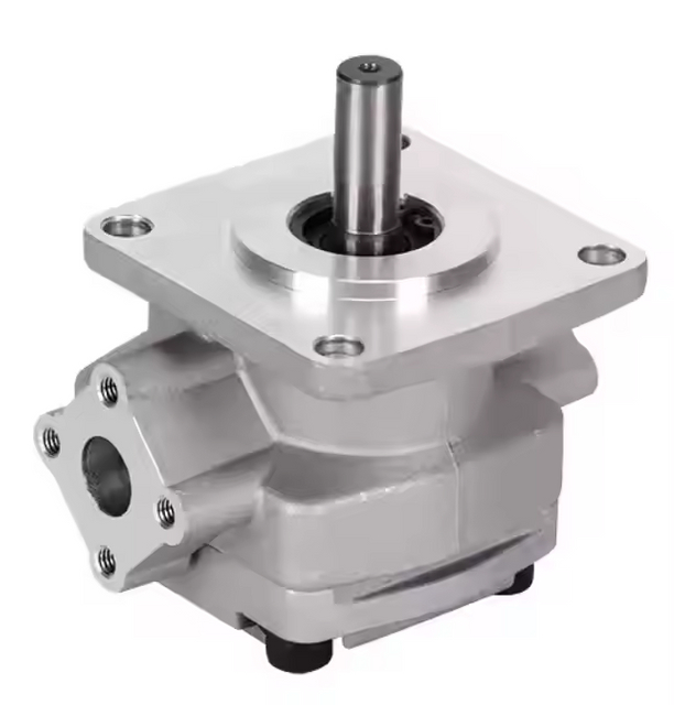
Pump replacements. If a new HGP gear pump is installed into an old tank, do not assume the tank is innocent. Look for foam, sediment, a wrong pickup height, restricted suction plumbing and return oil aimed at the inlet side. A matching shaft and pressure rating do not prove a healthy inlet environment.
Common baffle-design mistakes
Putting return and suction connections close together because that shortens fabrication.
Sizing a baffle opening from average flow while ignoring rapid cylinder return, relief flow or multiple functions.
Measuring tank volume but not the minimum operating level at full actuator extension.
Routing return oil above the fluid surface and then blaming the pump for foam.
Using a baffle that cannot be inspected, cleaned or correctly reinstalled.
Treating the breather, filter, cooler and suction pipe as separate purchases instead of one reservoir system.
Using a rule of thumb from an open industrial circuit for a closed-loop charge system.
Commissioning and maintenance checks after fabrication
The tank should be checked as a system before it is treated as a finished enclosure. A clean drawing can still fail on the first start if return oil has a different route from the one assumed, if a removable baffle is not reinstalled correctly after cleaning, or if the pickup becomes uncovered during a real machine movement.
Begin with a clean, safe commissioning procedure from the machine manufacturer. Record oil level before starting, at the longest expected actuator extension and after return. Note the fluid temperature at start and during the duty that creates the complaint. A sudden change between cold and hot conditions is useful evidence: cold oil may magnify suction and return restrictions, while warm oil can reveal leakage, aeration or an inadequate cooling path.
Then inspect the reservoir while the function is operated under a controlled, safe condition. Watch for a return jet that breaks the surface, foam collecting near the suction side, oil sloshing around a baffle opening, a breather that becomes wet with oil, or a level that approaches the pickup. Do not put hands or tools into an operating reservoir. A sight glass, safe viewing port, temperature reading and a well-planned test are more useful than opening covers near moving machinery.
Pressure and flow tests should stay tied to the failure story. A pump outlet gauge may show normal pressure while the inlet is starved or a return filter/cooler creates unwanted backpressure. Check the hydraulic-station low-pressure diagnostic when the source pressure is weak, and compare the symptom with the quick-coupler pressure-drop guide when an attachment or connection changes the return condition. Those pages do not replace a reservoir review; they keep a tank problem from being mistaken for a pump-only fault.
After the initial run, inspect the return filter indicator and any removed element for evidence of commissioning debris. Look at the breather and filler practice, not just the internal baffle. If air or water continues to enter through an open cap, damaged gasket or wet service procedure, the tank may keep returning a contamination problem to the pump even when its internal flow path is good.
Maintenance access deserves an explicit decision. A tank should allow the team to drain old oil, remove settled debris, inspect the pickup and return diffuser, check baffle attachment and clean reachable internal surfaces without leaving loose parts behind. If the baffle must be removed, mark its position and retention method on the drawing. A plate installed backward or with an unplanned gap can recreate the direct flow path it was meant to stop.
For high-duty systems, compare temperature, foam, filter restriction and noise before and after a representative cycle. The purpose is not to chase one target reading. It is to establish a repeatable baseline and find changes before they become a pump, valve or seal failure. Keep the baseline with the unit schematic, reservoir drawing and service record; it gives the next technician more value than an undocumented tank modification.
Who should not use a generic baffle layout?
Do not release a tank from a web sketch alone when it supports a safety-critical function, a personnel lift, a high-inertia or high-speed machine, a pressurized reservoir, a closed-loop hydrostatic circuit, severe mobile-machine attitude, water-glycol or other special fluid, or an application with unknown thermal load. These designs need the machine schematic, applicable standard, exact component data and an engineering review.
Also pause if the existing system has repeated pump failures, visible metal in the tank, foam that persists after warm-up, a collapsed suction hose, unknown return routing or a tank that cannot be opened for cleaning. A new baffle will not make contaminated oil or damaged components safe to reuse.
Data to send for a reservoir-layout review
Send BLINCE the following before requesting a hydraulic power unit or reservoir quotation:
tank drawing or photos with internal dimensions, minimum and maximum oil levels, and available cleanout access;
pump type, displacement, speed and actual flow; maximum combined return flow and relief/cooler/filter bypass paths;
cylinder or motor volume changes, cycle times and simultaneous-function duty;
oil type, viscosity range, cold-start and normal operating temperature;
suction pickup, return, breather, filter and cooler locations; hose/pipe diameters and lengths;
machine orientation, vibration, ambient conditions, contamination history and any foam/noise symptom;
BLINCE can use that package to compare the pump, tank, filtration, cooling, breather and connection layout, identify missing data and outline a suitable custom HPU direction. Final suitability still requires the selected product data, drawing and machine-level review.
FAQ
What does a hydraulic reservoir baffle do?
It separates the return-oil zone from the pump-suction zone so oil follows a longer, calmer route. That can support air release, contaminant settling and reduced return-to-suction short-circuiting. It does not replace correct tank volume, cooling, filtration or suction plumbing.
How high should a hydraulic tank baffle be?
There is no safe universal height. It must be designed around the lowest operating oil level, the intended flow path, opening area, service access and tank construction. Confirm the dimensions in the project drawing and applicable product/system documentation.
Should return oil pass over or under a baffle?
Both arrangements appear in real designs. The correct route depends on the baffle, return discharge, air-separation requirement, oil-level range and cleaning plan. The important point is to prevent a fast shortcut from return to suction without creating excessive turbulence or an inaccessible dirt trap.
Can a baffle solve pump cavitation?
Only when poor tank circulation or aeration contributes to the inlet problem. It cannot correct a low oil level, blocked breather, undersized suction line, collapsing hose, wrong oil viscosity, excessive pump speed or a damaged pump.
How do I estimate baffle-opening area?
Use A = Q ÷ v as a first calculation, with flow in m³/s and a chosen screening velocity in m/s. Label the result as preliminary and then check actual return flow, viscosity, level range, construction and the selected supplier’s design guidance.
Is a reservoir baffle needed in every hydraulic system?
Many reservoirs use one or more flow-control features, but the final arrangement depends on circuit type, package size, fluid, duty, return arrangement and manufacturer requirements. Closed-loop or pressurized systems may need a different approach from a conventional open industrial reservoir.
Request a layout review
If the pump is noisy, oil foams, a tank runs hot or you are specifying a new HPU, send the tank drawing, pump and return-flow data, oil-level range, fluid/temperature, piping layout and duty cycle. BLINCE can identify whether the first issue is a baffle path, return arrangement, breather, suction route, filter/cooler restriction or a wider system mismatch before a power unit is quoted.
This article is a general engineering guide. Final component selection should be based on machine drawings, measured hydraulic data, working conditions, safety requirements, and confirmation from a qualified hydraulic engineer or supplier.
Blince Hydraulic Team
Blince Hydraulic is an industry-leading company dedicated to precision-engineered fluid power manufacturing and custom hydraulic solutions. Backed by decades of deep field expertise in industrial machinery and thousands of successful global deployments, our engineering team focuses entirely on high-performance hydraulic component manufacturing, including specialized orbital motors, high-pressure travel drives motor, and robust directional control valves. Our production infrastructure utilizes state-of-the-art multi-axis CNC machining systems and is fully ISO 9001 certified to guarantee repeatable volumetric accuracy across every single manufacturing run.
We deliver fast, highly dependable, and cost-efficient hydraulic solutions to heavy industry distributors, machinery OEMs, and maintenance crews across more than 150 countries. Whether your active project calls for a small-volume batch of customized shaft profiles or a large-scale production run of severe-duty cast iron gear pump, we configure our flexible production schedules to meet your target lead times with total pricing predictability. Partnering with Blince means securing maximum system efficiency, elite material quality, and uncompromised fluid power professionalism.
To learn more about our complete product lineup, visit our official website: www.blince.com.