A gerotor pump uses an inner rotor and an outer rotor on offset axes. The outer has one additional lobe. As the shaft turns, the volume between their profiles grows near the inlet and contracts near the outlet. This sequence takes in liquid and delivers it to the connected circuit.
The same rotor name appears in lubrication, cooling and hydraulic-supply catalogs. Read it alongside the assembly code and duty description. Housing, porting, driver and fluid compatibility belong to that particular assembly; a search for the name can also return hydraulic motors and unfinished rotor sets.
Start with a hypothetical request for 26 L/min. That figure might be delivery at the required pressure, or a catalog value at another speed with very little resistance. These are different offers. The calculation below follows a circulation example from displacement to delivered flow and drive power, so the missing conditions can be written into a purchasing request rather than left for the installer to discover.
Follow one pocket through the pumping cycle
The inner and outer elements rotate about separate, fixed axes in the conventional gerotor pump described here. Their centers remain eccentric. Where the profiles move apart, a pocket enlarges and communicates with the inlet. Where they move together, its volume decreases and liquid leaves through the delivery port. Port windows connect the appropriate pockets to the appropriate side of the circuit.
The eccentric geometry and one-lobe difference are illustrated in Cascon's technical explanation of the gerotor pumping element. A rotor-set drawing specifies only part of the eventual pump. Its clearances within the housing, port windows, bearings and seals also enter the finished assembly's performance and installation requirements.
Follow the delivery port to the filter, cooler and pipework on a circulation schematic. Each contributes resistance before the oil returns to the reservoir. A shutoff in that path needs particular attention: the shaft can continue driving the positive-displacement element against a closed outlet. Pressure protection must be provided by the arrangement approved for the pump and circuit. It cannot be inferred from the open delivery arrow on a rotor animation.
The port windows are worth studying alongside the rotor outline. Trace where a growing pocket first communicates with the inlet and where a contracting pocket opens to delivery. Then locate the direction arrow and its viewing reference. “Clockwise from the shaft end” is an unambiguous drawing note; a clockwise arrow viewed from the opposite cover is not the same instruction.
The geometric calculation assumes filled pockets and ignores oil slipping through clearances. Neither assumption is assured in service. This is why the order review eventually comes back to a flow curve for the assembled pump, even if the geometry and displacement have already been identified correctly.
Separate a gerotor pump from nearby product names
Several names encountered in a search describe related geometry or different functions. They should not be treated as interchangeable ordering descriptions.
Name on a search result or drawing
What to establish
What the name leaves open
Gerotor pump
A shaft-driven pumping assembly with the specified rotor set
Pressure rating, viscosity range, rotation and port arrangement
Internal gear pump
Which internal-gear architecture is shown
Whether it uses gerotor geometry or a different arrangement, including a crescent separator
External gear pump
The paired external gears and the complete pump specification
Whether it can replace the original installation
Gerotor or orbital hydraulic motor
Oil drives the motor's output shaft
Whether operation as a pump is approved at all
Gerotor element or rotor set
The component drawing and intended pump assembly
Housing clearances, bearings, port plate and finished-pump performance
For the orbital motor entry, follow the power direction: supplied oil normally turns the output shaft. A proposal to drive that shaft and use the unit as a pump requires the manufacturer's approval. The review must cover the proposed duty, lubrication, porting, shaft support and any drain requirement. Similar rotor geometry alone supplies none of that approval.
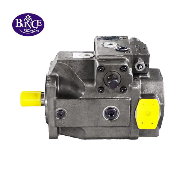
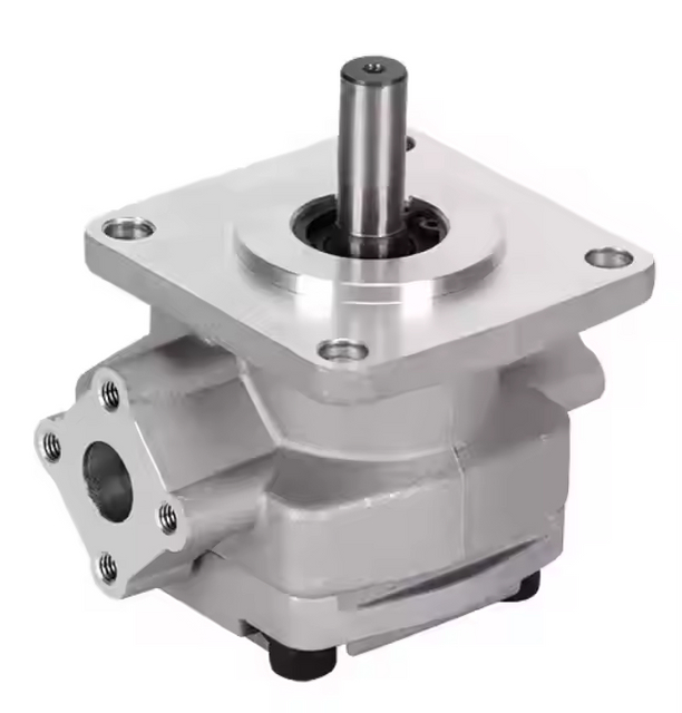
The distinction also helps with purchasing language. If an inquiry says only “g rotor pump,” add a photograph of the complete unit and its nameplate. A supplier otherwise has to guess whether the request concerns a rotor set, a complete oil pump or a hydraulic motor that has been described loosely.
BLINCE's hydraulic pump catalog is a place to start a product inquiry. In that inquiry, identify the proposed function and ask which offered pump family can support it. The technical explanation here should not be read as a stock list or confirmation of a particular BLINCE gerotor package.
The pressure rating belongs to the series and configuration
Gerotor pumps appear in several kinds of oil circuit. The Parker QPM3 documentation describes a low-pressure oil-circulation family and recommends a maximum working pressure of 10 bar for the documented arrangement. Its listed tasks include moving oil through cooling and filtration systems. This is evidence about QPM3, rather than a universal gerotor pressure limit.
A contrasting published example appears in Parker's PGG gerotor series in its pump catalog: several frame sizes are listed at 138 bar maximum continuous pressure, while another is listed at 103.5 bar. Keep those numbers under the PGG heading in a comparison. Moving them to a generic “gerotor pressure” row would erase the very distinction the two catalogs illustrate. They are not specifications for a BLINCE replacement.
Use an operating-point row instead of collecting the largest figures on the page. For example, enter the desired delivery, pump rpm, pressure difference and oil condition together. The corresponding point on the candidate's curve is the evidence to review. A restriction on simultaneous pressure and speed belongs beside that row, with a second row covering the cold start.
An actuator supply and a low-pressure cooler loop can have different component pressure limits. Enter the downstream filter and exchanger ratings separately from the pump's rating, and compare them with the proposed cold-start duty. Their bypass documentation belongs with that comparison.
Three purchasing descriptions lead to three different investigations:
“Replace the lubrication pump” calls for the original oil specification, delivery points and pressure controls.
“Feed an independent filter loop” calls for the required circulation, expected restriction and reservoir arrangement.
“Power a cylinder” calls for actuator flow, load pressure, control arrangement and the complete operating cycle.
These duties can share the word gerotor while requiring different hardware. A low advertised price or a matching displacement does not resolve that difference.
Calculate delivery at the shaft speed that will occur
For a fixed-displacement pump, the first estimate of delivered flow is:
Q = D × n × ηv / 1,000
Here Q is delivery in L/min, D is displacement in cm³/rev, n is pump shaft speed in rpm, and ηv is volumetric efficiency at the operating condition. Parker's F12 service manual, basic pump formulas on printed page 2 gives this general relationship. The formula is useful across pump calculations. F12 product ratings are not gerotor ratings.
For the hypothetical warm-running duty, enter D = 20 cm³/rev, n = 1,450 rpm and ηv = 0.90. These inputs were chosen to explain the calculation; they are neither measurements nor BLINCE ratings:
Q = 20 × 1,450 × 0.90 / 1,000 = 26.1 L/min
Without the efficiency allowance, the geometric estimate is 29 L/min. If a cooler requires 28 L/min under this condition, the geometric result would make the pump appear sufficient. The assumed delivered result falls short. That is a reason to inspect a performance curve, rather than order from displacement alone.
Item in this constructed example
Value
Interpretation
Geometric displacement
20 cm³/rev
Volume per shaft revolution before leakage allowance
Shaft speed
1,450 rpm
Actual input speed assumed for this duty
Assumed volumetric efficiency
0.90
An illustrative running value requiring confirmation
Geometric flow
29 L/min
Does not account for incomplete filling or leakage
Estimated delivered flow
26.1 L/min
Suitable for preliminary comparison only
For a second speed row, substituting 1,000 rpm gives 18 L/min with the illustrative 0.90 efficiency retained. A variable-speed duty therefore needs both rows. So does a geared drive when someone has entered driver rpm in the pump-speed cell: the ratio must first be applied to obtain the pump's own rpm.
The next piece of evidence is the curve at the specified viscosity and pressure, particularly around the lowest useful shaft speed. That replaces the assumed efficiency used here.
Add pressure difference and drive power to the example
For the next row of the example, assign an 8 bar pressure difference to the loop at 26.1 L/min. The oil receives hydraulic power at this rate:
Ph = Q × Δp / 600 = 26.1 × 8 / 600 = 0.348 kW
Assume hydro-mechanical efficiency of 0.85 for the same warm running condition. Combined with the assumed volumetric efficiency of 0.90, overall efficiency is 0.765. The estimated shaft input is then:
Pshaft = 0.348 / 0.765 = 0.455 kW
The corresponding running shaft torque is approximately 3.00 N·m, using D × Δp / (20π × ηhm). The factor 20π converts bar and cm³/rev to N·m. Catalog formulas often round this factor to 63.
This is a steady operating estimate. It does not select an electric motor, establish starting torque or account for a coupling, belt or gearbox. The driver still needs a review of starting conditions, operating speed, overload behavior, duty and its own rating method. The electrical supply and motor controls belong in that review when the package is electrically driven.
Now change only the illustrative pressure difference to 80 bar. At unchanged flow and assumed efficiencies, calculated shaft demand becomes about 4.55 kW. Ten times the pressure difference means ten times the calculated running input in this simplified example. This is not permission to run the original hypothetical pump at 80 bar. It shows how incomplete the phrase “26 L/min pump” is without a pressure duty.
A quoted package should therefore state both the required flow and pressure difference, rather than just an electric motor power or pump displacement. Identify where the pressure is measured. A gauge beside a remote machine inlet cannot by itself establish the differential pressure across a circulation pump on another branch.
Check the inlet before increasing pump size or speed
A larger displacement is an attractive answer to a shortfall on the flow sheet. It also asks the inlet to supply more oil per revolution. Before changing that cell, draw the path from the lowest permitted reservoir level to the pump's inlet connection. There may be a strainer, an elbow and a shutoff valve in that path that never appeared in the original pump quotation.
Record bores rather than relying on hose outside diameters. An adapter can introduce a smaller passage than either adjoining port, and a hose unsuitable for suction service may not maintain its internal shape under the actual conditions. Elevation and line length belong on the sketch too. This gives an engineer something more useful to assess than “the reservoir is nearby.”
Put the pressure reference beside an inlet reading. For a hypothetical local atmospheric pressure of 100 kPa, an inlet at 90 kPa absolute corresponds to 10 kPa of vacuum relative to that atmosphere. Writing only “90 kPa” or “10 kPa” without the reference invites the wrong comparison. Local atmosphere, including the effect of altitude, and the assembly's documented inlet and viscosity limits must be accounted for in acceptance.
Two service descriptions deserve different follow-up questions: “bubbles appeared after a hose change” and “noise begins with cold oil at high rpm.” The first directs attention toward air entry and the changed connection, even if there is no outward stain. The second calls for an inlet-condition review, including the possibility of local pressure falling low enough for vapor formation. Both remain observations to investigate rather than findings that prove the pump is worn.
Keep reservoir level, oil condition and operating state with each observation. Qualified personnel can then plan the necessary rated instrumentation under the machine's isolation and test procedure. Do not loosen an energized fitting, use a hand to find a pressure leak or dry-run the pump to test priming. None of that is needed to collect the identifiers and external layout information for an initial inquiry.
Treat cold starting and hot running as separate duties
The warm-running example leaves a cold start unanswered. More viscous oil can make the inlet harder to supply and increase resistance in the connected equipment. At the other end of the duty, thinner hot oil can alter leakage and delivered flow. A curve checked halfway between these conditions cannot close both questions.
The fluid supplier's viscosity-temperature information can populate a short operating-condition record. Leave an entry unknown if it has not been established, rather than copying the nominal grade into every viscosity cell:
Condition record
Oil information
Circuit information to compare
First start after standing
Expected starting oil temperature and corresponding viscosity
Inlet filling, connected restriction and driver starting demand
Normal work
Working oil temperature and viscosity
Delivered-flow curve and loop pressure loss at that condition
Hottest intended operation
Upper working oil condition, separately from ambient
Permitted pump duty, delivered flow and connected-component limits
Compare the pump, filter and cooler information using matching viscosity references. An ISO oil grade by itself cannot fill all these rows, and a cold filter-loss value paired with a warm pump-delivery value would mix two states. Retain the element and housing limits alongside the filter's bypass information.
Label bypasses by destination on the sketch. For example, a line around an element and a line returning pump delivery directly to the reservoir have very different consequences for treatment of the oil. The circuit may contain both. Their opening behavior and pressure-protection roles should be resolved individually from the component and machine documentation.
This gives a practical way to assess an offer for a larger pump: follow the additional delivery through the proposed paths at each fluid condition. If the extra oil returns through bypass, it may add drive demand while contributing little to the intended filtration or cooling. A higher flow on the quotation is therefore a question for the loop calculation, not an automatic improvement.
Read circulation flow in the context of the complete loop
Trace the connections to establish an independent circulation loop: reservoir, pump, treatment equipment and return to that reservoir. A branch feeding lubrication, charge oil or a control function changes the job shown by the same pump symbol. Such a branch needs to be included before the loop is considered independent for a sizing change.
For the simple reservoir loop in our example, five minutes at a constant 26.1 L/min moves a calculated 130.5 L through the delivery path. This is useful for a volume balance. It is not evidence that every parcel in a 130.5 L tank has passed through the filter once. Return placement and mixing affect which oil reaches the inlet again, while filter performance governs contaminant removal.
A cooling offer needs the heat duty as well as the flow row. The exchanger's performance information brings in entering oil temperature and the cooling air or water condition. It can then be assessed at the chosen circulation point. The resulting pressure loss returns to the pump calculation; the two selections have to describe the same loop.
For one hypothetical bypass path, enter Q = 10 L/min and Δp = 8 bar in the pressure-flow power relation. The calculation gives 0.133 kW for this path alone; a total heat balance would also need the other established losses, including those of the driver and pump.
Tracing the circuit may reveal that the pump also feeds an essential service, such as steering or brake support. Include the machine's approved loss-of-supply behavior in that review. The freedom to alter an independent filter loop should not be carried over to such a function without the necessary circuit approval.
Compare a replacement as an assembly
When the electric-motor plate is the easiest tag to photograph, label that photograph “driver.” Add the pumping-section identifier and package number, where fitted, as separate entries. Retain full codes, suffixes and revisions before cleaning or dismantling changes their legibility. This prevents a readable driver tag from being mistaken for identification of the whole circulation package.
For the mechanical comparison, put the two drawings on the same reference face. Compare pilot, mounting face, shaft projection and coupling engagement from that face. A matching bolt pattern can conceal a projection difference that loads a coupling incorrectly. At the oil connections, establish the thread and sealing method together; being able to start an adapter in a port proves neither sealing nor load capacity.
Replacement check
Evidence to retain
A mismatch can change
Displacement and delivery
Old code, pump curve and required operating points
Available circulation or actuator speed
Rotation and port assignment
Manufacturer drawing with viewing reference
Filling, delivery and pressure-protection path
Shaft and mounting
Dimensioned comparison including coupling engagement
Alignment, bearing load and mechanical fit
Inlet and outlet connections
Port standard, seal detail and hose arrangement
Restriction, sealing and installation space
Internal valves
Complete option code and circuit symbol
Relief behavior, recirculation and downstream supply
Fluid and seals
Approved fluid, viscosity and temperature range
Material compatibility and leakage behavior
Driver and duty
Required torque, speed, starting condition and cycle
Overload, delivery and thermal performance
Installation space adds another drawing comparison. A port moved to the opposite face might occupy space used by a frame member, while a longer driver might leave no room for coupling alignment or later removal. Annotate those obstructions on the layout. They are purchasing constraints even when the hydraulic operating point is satisfactory.
Attach the removed pump's inspection findings to the dimensional comparison, including any work that addressed a contamination source or blocked passage in the retained installation.
Prepare a quotation request that identifies the unresolved decision
For the hypothetical duty, an inquiry can start “independent reservoir circulation, estimated 26.1 L/min at 1,450 pump rpm, estimated 8 bar differential at the stated warm-oil condition.” Put the fluid and temperature range next. Keep the estimate labels until measurements or verified component data replace them, so the supplier can see both the current design point and its uncertainty.
For a replacement, attach the old codes and interface comparison to that operating-point record. For a new loop, attach the proposed treatment equipment and routing instead. A marked schematic supplies the inlet, outlet and bypass destinations for either request. Also identify any essential machine function that shares the supply.
Send that packet through BLINCE's official inquiry page, asking for the offered family, complete option code, drawing and performance evidence at the stated duty. The response might support a candidate, point toward another pump architecture or identify a missing input. Those are useful technical outcomes before price is settled.
Keep the reviewed configuration with the purchase record. If a competitor's old code was the starting identifier, retain the actual comparison rather than replacing it with an unsupported “equivalent” label. Procurement and installation can then work from the same documented selection.
This article is a general engineering guide. Final component selection should be based on machine drawings, measured hydraulic data, working conditions, safety requirements, and confirmation from a qualified hydraulic engineer or supplier.
Blince Hydraulic Team
Blince Hydraulic is an industry-leading company dedicated to precision-engineered fluid power manufacturing and custom hydraulic solutions. Backed by decades of deep field expertise in industrial machinery and thousands of successful global deployments, our engineering team focuses entirely on high-performance hydraulic component manufacturing, including specialized orbital motors, high-pressure travel drives motor, and robust directional control valves. Our production infrastructure utilizes state-of-the-art multi-axis CNC machining systems and is fully ISO 9001 certified to guarantee repeatable volumetric accuracy across every single manufacturing run.
We deliver fast, highly dependable, and cost-efficient hydraulic solutions to heavy industry distributors, machinery OEMs, and maintenance crews across more than 150 countries. Whether your active project calls for a small-volume batch of customized shaft profiles or a large-scale production run of severe-duty cast iron gear pump, we configure our flexible production schedules to meet your target lead times with total pricing predictability. Partnering with Blince means securing maximum system efficiency, elite material quality, and uncompromised fluid power professionalism.
To learn more about our complete product lineup, visit our official website: www.blince.com.