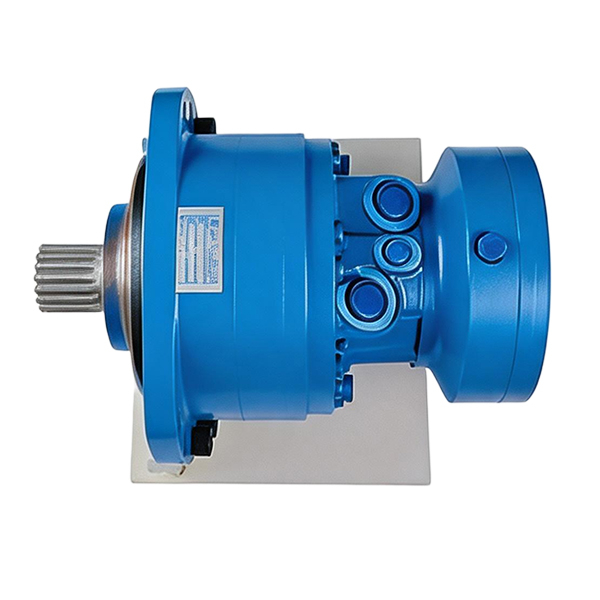
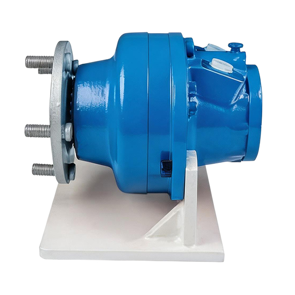
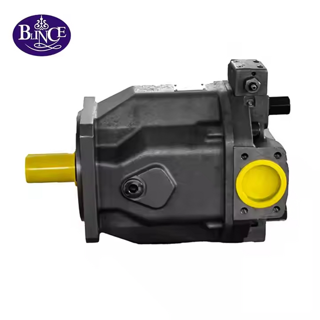
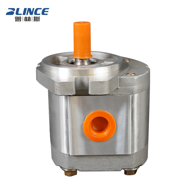
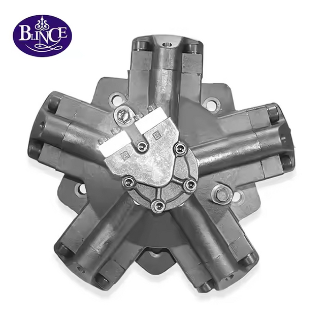
Improper actuator sizing carries severe operational consequences on the job site. Undersizing a unit leads to frequent stalling, inadequate load handling, and premature mechanical failure under heavy duty cycles. Oversizing results in wasted energy, excessive heat generation, and unnecessarily bulky system footprints that complicate installation. System designers and procurement engineers must constantly balance mechanical load requirements with available hydraulic power. You have to navigate complex trade-offs between component types, volumetric efficiencies, and physical space constraints on the machine.
Specifying the exact rotary actuator for your application requires a systematic, engineering-first framework. You cannot rely on guesswork when dealing with heavy loads and high pressures. Calculating torque, speed, and displacement accurately ensures your equipment operates reliably under its specific duty cycle and environmental conditions. This guide provides the foundational formulas and practical steps needed to select the optimal Hydraulic Motor for your next project.
Torque and Pressure Relationship: Motor torque is directly proportional to system pressure and motor displacement; accurately calculating the pressure drop (Delta P) across the motor is critical for sizing.
Speed and Flow Dynamics: Motor speed is dictated by the input flow rate and displacement, but volumetric inefficiencies (internal leakage) will reduce actual operating speed under load.
HSLT vs. LSHT Selection: Applications dictate the fundamental classification choice—High-Speed, Low-Torque (HSLT) for rapid, continuous rotation, or Low-Speed, High-Torque (LSHT) for heavy, direct-drive positioning.
Efficiency Derating: Theoretical calculations must always be derated using mechanical and volumetric efficiency factors specific to the motor design (gear, vane, or piston) to ensure real-world performance.
Table of Contents
Toggle
The Core Variables of Hydraulic Motor Selection
Defining Displacement
Displacement represents the volume of fluid required for one complete revolution of the output shaft. It serves as the foundational metric linking hydraulic input to mechanical output. Engineers typically measure displacement in cubic inches per revolution (cir) or cubic centimeters per revolution (cc/rev). A larger displacement yields higher torque at a given pressure but requires more flow to maintain a specific speed. When you tear down a failed unit in the field, you often find that an incorrectly specified displacement led to over-speeding and catastrophic bearing failure.
Understanding displacement means recognizing the physical limits of the internal rotating group. Whether you are dealing with a gerotor star or an axial piston barrel, the physical void that fills with fluid dictates the baseline performance. You cannot force more fluid through the unit than its displacement and maximum RPM rating allow without causing severe cavitation or blowing shaft seals.
Understanding Torque (Starting, Running, and Stall)
Torque is the rotational force generated by the actuator. Starting torque refers to the force required to break static friction and initiate motion. Running torque is the force needed to maintain continuous motion under load. Stall torque occurs when the load exceeds the motor's capacity, stopping rotation entirely. Mechanical efficiency drops significantly at low speeds. You will always need higher pressure to achieve starting torque compared to running torque.
In heavy industrial applications like winch drives or conveyor belts, starting torque is the most demanding parameter. A load that requires 2,000 lb-in of torque to keep moving might require 3,000 lb-in just to break static friction. If you size the system based only on running torque, the machine will stall on startup. Always calculate the maximum load condition and ensure your system pressure can deliver the required starting torque.
Determining Operating Speed (RPM)
Application requirements dictate the target rotational speed (RPM). This speed directly relates to the available hydraulic flow rate, usually measured in gallons per minute (GPM) or liters per minute (L/min). If your system cannot supply adequate flow, the unit will not reach its target RPM. Volumetric efficiency also plays a major role, as internal leakage reduces the actual speed achieved under load.
Speed is never a static number in fluid power. As the load increases, system pressure rises, which forces more fluid to bypass the internal clearances. This internal slip means your actual RPM will always be slightly lower than your theoretical RPM. Field technicians often use tachometers to measure this speed drop under load to diagnose internal wear before a complete failure occurs.
Operating Pressure and Delta P
Rotary actuators operate based on the pressure differential (Delta P) between the inlet and outlet ports. You cannot rely solely on the maximum system pressure rating. Return-line backpressure reduces the effective pressure available to generate torque. Always subtract the return line pressure from the inlet pressure to determine the true working Delta P for your sizing calculations.
Consider a system with a 3,000 PSI relief valve setting. If the return line pushes fluid through a restrictive filter and a long hose run, you might have 300 PSI of backpressure at the outlet port. Your actual working pressure (Delta P) is only 2,700 PSI. Failing to account for backpressure is a common sizing error that results in underperforming equipment on the job site.
Parameter
Definition
Unit of Measure
Field Impact
Displacement
Fluid volume per revolution
cir or cc/rev
Determines baseline flow requirement and torque capacity.
Delta P
Inlet pressure minus outlet pressure
PSI or Bar
Dictates the actual torque generated at the shaft.
Volumetric Efficiency
Ratio of theoretical to actual flow
Percentage (%)
Causes speed drop under heavy loads due to internal slip.
Mechanical Efficiency
Ratio of theoretical to actual torque
Percentage (%)
Requires higher pressure to overcome internal friction.
Step-by-Step Hydraulic Motor Sizing Formulas
Calculating Required Torque
To calculate theoretical torque, use the standard formula: Torque (lb-in) = (Pressure x Displacement) / (2 x π). This provides a baseline figure. You must adjust this theoretical output using the mechanical efficiency rating of your chosen component type. Multiply the theoretical torque by the mechanical efficiency percentage to determine the actual torque delivered to the shaft.
For example, if your theoretical calculation yields 4,000 lb-in, but you are using a gear unit with an 80% mechanical efficiency, your actual output torque is only 3,200 lb-in. If your load requires 3,800 lb-in, this unit will stall. You must either increase the system pressure or select a unit with a larger displacement.
Calculating Required Speed and Flow Rate
Determine the required flow rate using this standard formula for US units: Flow Rate (GPM) = (Displacement x RPM) / 231. This calculation gives you the theoretical flow. You must adjust this requirement using the volumetric efficiency rating. Divide the theoretical flow by the volumetric efficiency percentage to account for internal slip and determine the actual flow your pump must provide.
If your theoretical flow requirement is 15 GPM, and the unit has a 90% volumetric efficiency, your actual required flow is 16.6 GPM (15 / 0.90). If your pump only delivers 15 GPM, the actuator will rotate slower than your target RPM under load. Always size the pump to accommodate the volumetric losses of the entire system.
Calculating Hydraulic Horsepower (HP)
Evaluate overall power requirements using the hydraulic horsepower formula: HP = (GPM x PSI) / 1714. This metric helps you verify that the primary pump and prime mover can adequately support the selected actuator. If the calculated horsepower exceeds your power unit's capacity, you must adjust your system parameters or upgrade the prime mover.
Horsepower calculations reveal the true energy demands of your machine. A high-speed, high-pressure application will draw significant power from the diesel engine or electric motor driving the pump. If you undersize the prime mover, the engine will bog down or the electric motor will trip its thermal overload protection during peak duty cycles.
Worked Sizing Example: Step-by-Step Practical Scenario
Consider sizing a drive for a heavy aggregate conveyor belt. The target parameters are a required output speed of 120 RPM, a required running load torque of 4,500 lb-in, and a maximum available system pressure of 2,500 PSI (accounting for backpressure).
Calculate Theoretical Displacement: Rearrange the torque formula: Displacement = (Torque x 2 x π) / Pressure. (4,500 x 6.28) / 2,500 = 11.3 cir.
Apply Mechanical Efficiency: Assume an 85% mechanical efficiency for the selected design. Adjusted Displacement = 11.3 / 0.85 = 13.3 cir. You need a unit with at least 13.3 cir displacement.
Calculate Theoretical Flow: Flow Rate = (Displacement x RPM) / 231. (13.3 x 120) / 231 = 6.9 GPM.
Apply Volumetric Efficiency: Assume a 90% volumetric efficiency. Actual Required Flow = 6.9 / 0.90 = 7.6 GPM.
Verify Power Requirements: HP = (7.6 GPM x 2,500 PSI) / 1714 = 11.08 HP. Ensure your power unit can deliver at least 12 HP continuously.
Utilizing Interactive Sizing Calculators and Diagrams
Leverage online torque and speed calculators to accelerate the design process. These tools allow you to input variables and instantly see the results, reducing manual calculation errors. Use interactive schematic diagrams to visualize how changes in pressure and flow alter performance curves. Cross-reference calculator outputs with manufacturer specification sheets to confirm real-world suitability.
While calculators provide a solid baseline, they do not account for environmental factors like extreme cold affecting fluid viscosity or high ambient heat degrading volumetric efficiency. Always use your field experience to add appropriate safety margins to the calculator's theoretical outputs.
Evaluating Hydraulic Motor Classifications: HSLT vs. LSHT
High-Speed, Low-Torque (HSLT) Applications
HSLT units typically operate at speeds exceeding 500 RPM, often reaching up to 3,000 RPM or more. Common use cases include fan drives, generator drives, and centrifugal water pumps. These applications require rapid, continuous rotation rather than heavy lifting. The internal components are designed to handle high rotational velocities without excessive heat buildup or bearing wear.
The primary limitation of HSLT designs is the lack of low-speed torque. If your application requires high torque at the final drive, you will need to integrate a mechanical gearbox. Adding a gearbox increases the physical footprint, adds maintenance points, and introduces mechanical power losses. You must weigh the simplicity of the HSLT unit against the complexity of the required mechanical reduction.
Low-Speed, High-Torque (LSHT) Applications
LSHT units operate at speeds below 500 RPM, often functioning smoothly down to 1 RPM without cogging. Common applications include winch drums, heavy conveyors, wheel drives on mobile equipment, and industrial mixers. These designs offer the distinct advantage of direct-drive implementation. They generate massive rotational force directly at the output shaft.
By eliminating the need for a gearbox, you reduce maintenance requirements, save physical space, and simplify the overall mechanical assembly. LSHT units typically use gerotor or radial piston designs to achieve this high torque output. They are built ruggedly to handle heavy side loads and harsh operating environments common in construction and mining.
Classification
Typical RPM Range
Primary Advantage
Common Applications
HSLT (High-Speed, Low-Torque)
500 - 3,000+ RPM
High rotational velocity, compact size
Fan drives, centrifugal pumps, generators
LSHT (Low-Speed, High-Torque)
1 - 500 RPM
Direct drive capability, massive torque
Winches, wheel drives, heavy conveyors
Comparing Hydraulic Motor Designs (Features to Outcomes)
Gear Motors (External and Gerotor)
Gear designs feature a simple, rugged construction with very few moving parts. They offer high dirt tolerance, making them suitable for harsh environments where perfect fluid filtration is difficult to maintain. The external gear design uses two meshing gears, while the gerotor design uses an inner rotor and an outer stator. Both types are mechanically simple and easy to rebuild in the field.
However, they suffer from lower overall efficiency, typically ranging between 70% and 80%. They also generate higher noise levels due to the pressure ripples created by the meshing gears. They are generally limited to lower operating pressures compared to piston designs. Specify gear units for applications with moderate performance demands where mechanical simplicity is prioritized over maximum efficiency.
Vane Motors
Vane designs provide good starting torque and operate with lower noise levels than gear types. They maintain efficiency longer because the vanes self-compensate for wear by extending further against the cam ring as the tips degrade. This self-adjusting feature keeps internal leakage relatively constant over the unit's lifespan, providing predictable performance.
Conversely, they are susceptible to fluid contamination. Debris can cause the vanes to stick inside their rotor slots, leading to immediate catastrophic failure. They also require minimum operating speeds to keep the vanes extended via centrifugal force, unless they utilize spring-loaded mechanisms. They fit well in medium-pressure applications requiring smooth rotation and moderate efficiency.
Piston Motors (Axial and Radial)
Piston designs deliver the highest volumetric and mechanical efficiencies, often reaching up to 95%. Axial piston units handle extreme pressures and high speeds, making them ideal for heavy-duty hydrostatic transmissions. Radial piston units generate massive torque at low speeds, perfect for direct-drive wheel applications on heavy machinery.
The trade-offs include high manufacturing complexity and extreme sensitivity to fluid contamination. The tight tolerances between the pistons and the cylinder block require pristine fluid to prevent scoring. Reserve piston units for continuous-duty, high-power applications where precise control and maximum efficiency are mandatory for machine performance.
Implementation Realities and System Trade-offs
Heat Generation and Cooling Requirements
Mechanical friction and volumetric internal leakage convert directly into heat. Excessive heat degrades hydraulic fluid, destroys lubricating properties, and hardens elastomeric seals. You must evaluate the continuous duty cycle of your application to determine if a dedicated heat exchanger is necessary. Systems running near maximum pressure for extended periods will almost certainly require active cooling.
When fluid temperature exceeds 180°F (82°C), the viscosity drops significantly. This thinner fluid increases internal slip, which further reduces volumetric efficiency and generates even more heat. This thermal runaway can destroy a system in hours. Always size your reservoir adequately and install forced-air or water-cooled heat exchangers for high-duty-cycle applications.
Radial and Axial Load Capacities
Sprockets, pulleys, and direct vehicle weight apply significant physical forces to the output shaft. You must evaluate the bearing life (L10 life) under these specific radial (side) and axial (thrust) loads. Standard units are often designed only to transmit torque, not to support heavy external mechanical loads.
If the application forces exceed the standard bearing ratings, you must specify heavy-duty bearing options or integrate external overhung load adapters. An overhung load adapter isolates the internal shaft seals and bearings from the external mechanical stress, preventing premature shaft seal leaks and catastrophic bearing failure in belt-driven or chain-driven setups.
Shaft and Mounting Standards (SAE, ISO, and Metric)
Select correct mounting configurations, such as 2-bolt or 4-bolt flanges, based on standard SAE or ISO dimensions. Choose shaft connection styles carefully based on the load profile. Splined shafts handle high-torque, frequent-reversing loads much better than keyed shafts. Keyed shafts are prone to wallowing out and shearing under heavy shock loads.
Matching the physical torque-transfer demands with the appropriate standard ensures reliable mechanical integration. Using standard SAE or ISO mounts also simplifies future component replacement. If a unit fails in the field, finding a standard SAE B 2-bolt replacement is much easier than sourcing a proprietary mounting configuration.
Fluid Compatibility and Filtration Standards
Different internal designs require specific ISO cleanliness codes. Piston units demand strict filtration (often ISO 16/14/11 or better) to prevent catastrophic failure of the tight-tolerance components. Gear units tolerate more lenient filtration (ISO 20/18/15) due to their larger internal clearances.
Fluid viscosity directly impacts internal leakage and cold-start performance. Ensure your selected fluid maintains appropriate viscosity across the entire operating temperature range. Using a fluid that is too thick in cold weather will cause pump cavitation, while using a fluid that is too thin at operating temperature will cause excessive internal slip and loss of speed.
Vendor Selection and Supply Chain Considerations
Lifecycle Maintenance and Component Longevity
Procurement decisions must extend beyond the initial acquisition phase. Evaluate the frequency of wear part replacements and standard maintenance intervals. Highly efficient piston units in continuous applications often demonstrate greater longevity and lower energy consumption over time compared to simpler gear units. Focus on the durability of internal components relative to your specific duty cycle.
Consider the ease of field service. Can the shaft seal be replaced without removing the unit from the machine? Are rebuild kits readily available? A unit that requires factory service for a simple seal leak will cause unacceptable downtime on a busy construction site. Prioritize designs that allow for straightforward maintenance by field mechanics.
Lead Times, Availability, and Aftermarket Support
Select standard frame sizes and mounting flanges (SAE/ISO) to ensure supply chain resilience. Custom or proprietary mounting configurations severely limit your replacement options during unexpected downtime. If a custom unit fails, you might wait weeks for a replacement, halting production entirely.
Prioritize vendors who offer robust application engineering support during the prototyping phase. Reliable aftermarket support and readily available replacement parts are critical for maintaining continuous industrial operations. A vendor with a strong distribution network ensures you can get replacement parts quickly, minimizing machine downtime.
Conclusion
Successful sizing requires an iterative process that balances theoretical calculations with real-world efficiency losses and mechanical constraints. As an industry-leading manufacturer with over two decades of specialized fluid power expertise, BLINCE delivers a comprehensive portfolio of high-efficiency orbital motors, piston motors, and hydraulic pumps designed to match rigorous sizing specifications. Our ISO 9001-certified production lines utilize advanced manufacturing tolerances to maximize starting torque and minimize internal slip, ensuring that your calculated displacement translates directly into reliable field performance. Follow these actionable steps to finalize your selection:
Define your exact mechanical load requirements, including required running torque, starting torque, and target operating speed.
Calculate the theoretical displacement needed, then apply the appropriate mechanical and volumetric efficiency derating factors based on the specific design type.
Verify all physical load constraints, including radial shaft loads, operating temperatures, and available mounting space.
Gather your complete application data and consult with an application engineer to confirm your specifications before finalizing the system design.
FAQ
Q: How do you calculate hydraulic motor displacement?
A: Rearrange the standard flow formula to solve for displacement: Displacement = (Flow Rate x 231) / RPM. You must then divide this theoretical result by the unit's volumetric efficiency percentage to account for internal fluid slip and determine the actual displacement required to hit your target speed.
Q: What is the difference between starting torque and running torque in a hydraulic motor?
A: Starting torque is the force needed to overcome static friction and begin moving a load. Running torque is the force required to keep the load moving. Due to low initial mechanical efficiency and static friction, starting a load always requires higher pressure than running it.
Q: Why does my hydraulic motor lose speed under heavy load?
A: Speed loss under load is caused by internal slip, which affects volumetric efficiency. As system pressure increases to handle a heavier load, more fluid bypasses the internal working mechanisms through clearances, reducing the actual rotational speed at the output shaft.
Q: Can a hydraulic pump be used as a hydraulic motor?
A: Some specific gear and piston designs are bi-directional and interchangeable. However, many pumps lack the necessary internal bearing structures or case drain configurations required to handle the specific forces and pressures experienced when operating as a rotary actuator.
Q: What causes a hydraulic motor to overheat?
A: Overheating stems from excessive internal leakage due to component wear, operating continuously above rated pressure or speed, inadequate reservoir size, or fluid viscosity breakdown. All these factors increase friction and convert fluid energy directly into heat.
Q: How do I choose between a high-speed, low-torque (HSLT) and a low-speed, high-torque (LSHT) motor?
A: Choose LSHT for applications requiring direct-drive heavy lifting or turning, such as winches and conveyors. Choose HSLT for applications requiring rapid, continuous rotation, such as fan drives or centrifugal pumps, where high torque is not the primary requirement.
Q: How do I use a hydraulic motor torque and speed calculator for quick estimation?
A: Input your known design parameters, such as available flow, maximum pressure, and target RPM. The calculator provides theoretical outputs. Always cross-reference these results with manufacturer performance charts and apply efficiency deratings to confirm actual field suitability.