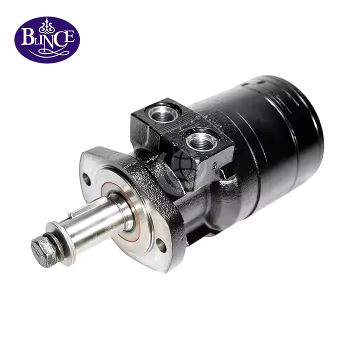
Hydraulic motor maintenance is often recorded as a list of completed tasks: oil checked, filter changed, bolts inspected. The log can be complete while the machine is still getting slower when warm. That gap matters because a maintenance record says what someone did; it does not, by itself, show whether the motor and circuit are behaving as they did under the same conditions last month. A useful plan connects observations to a repeatable operating state and then to a decision. Start with the exact motor and the machine manufacturer's instructions, then compare performance under known load, input speed, oil temperature, and flow conditions. The BLINCE hydraulic motor range spans multiple motor families, while the hydraulic motor parts diagram guide shows why an inspection plan must respect differences inside those families.
When a machine feels weak, it is tempting to repeat the most familiar maintenance action: change the oil, replace a filter, or order a motor. Each can be correct in the right case, but none is a diagnosis by itself. A dirty filter indicator, rising oil temperature, shaft-seal leak, and loss of speed point to different checks, and the visible symptom can originate upstream of the motor. Before spending time or parts, record the symptom and the conditions in which it appears. If the issue is already a loss of motion rather than planned maintenance, begin with the hydraulic motor troubleshooting and failure-analysis guide; if the machine will not turn at all, use the case-drain guide for that narrower symptom.
Short answer The motor range and contamination-control guide provide useful navigation when the exact machine documentation is in hand.
There is no single service interval or inspection list that fits every hydraulic motor and machine. Follow the equipment and exact motor manuals first. Build the remaining checks around duty, environment, oil condition, maintenance history, and measured trends. Compare like with like: the same load, prime-mover or pump speed, oil temperature, circuit configuration, and measurement points. If a trend changes, verify the reading and check the system before condemning the motor. Treat measured flow, shaft speed, case pressure, case-drain flow, leakage, noise, and temperature as clues with different meanings. Internal inspection and repair require the exact model limits and qualified procedures; a general checklist cannot substitute for them.
What a maintenance plan should control
A maintenance plan has three jobs. It should detect conditions that can harm the motor, preserve a usable baseline for future comparison, and define what happens when a reading changes. It is not a promise that a motor will last a fixed number of hours, and it is not a universal calendar. A plan for a frequently loaded travel drive in abrasive surroundings will need different observations from a lightly used conveyor drive in a clean indoor plant. The current BLINCE mobile machinery application page and industrial engineering application page illustrate how operating context varies; use the machine builder's duty description, not an application label alone, to set the actual checks.
Think of each maintenance entry as a small measurement record rather than a tick box. Write down the asset and motor identification, the action or observation, the operating state, the instrument or method, the reading, and the person who recorded it. “Oil hot” is difficult to compare six weeks later; “return oil at the marked test point, after the same loaded cycle, at the recorded ambient condition” is more useful. The same principle applies to leaks, sound, pressure, shaft speed, and vibration. When readings need a physical measurement point, the hydraulic pressure-gauge placement guide helps avoid comparing a pump-outlet value with a motor-port value as if they were interchangeable. The pressure-gauge placement guide and contamination-control guide give examples of recording context around test points and samples.
Before setting an interval, identify the actual motor. Record the complete nameplate and order code, displacement if stated, shaft and mounting arrangement, porting, rotation, brake or gearbox integration, and any case-drain connection. A machine can contain an orbital motor, gear motor, axial- or radial-piston motor, or an integrated travel drive; their lubrication paths, pressure limits, and service procedures are not interchangeable. The BLINCE OMR orbital motor page is one product example, not a maintenance specification for every OMR installation. If the label is unreadable or the unit has been modified, treat its identity and limits as unknown until they are confirmed from reliable documentation. Compare the motor range with the parts diagram guide when identifying the installed family and interfaces.
Let the exact manual set the limits
The equipment manual and exact motor documentation control operating limits, fluid requirements, case-drain arrangements, permissible shaft loads, inspection tasks, and service procedures. A supplier's general article can help organize questions, but it cannot supply a missing model limit. Danfoss's OMT/OMV ATEX user manual, for example, tells users to check the relevant motor information and machine/system requirements and describes regular checks for oil level, leakage, operating temperature, viscosity, oxidation, and contamination for those products. Its limits and instructions apply to the specified Danfoss motors and installation context, not automatically to BLINCE equipment or another manufacturer's motor. Use the manufacturer's OMT/OMV user manual as an example of a model-specific source, then locate the manual for the installed unit. The contamination-control guide and pressure-gauge placement guide provide fluid and measurement context while the exact installed-model manual controls.
A second example shows why a single “hydraulic motor rule” is unsafe. Parker's V14 service manual specifies V14 installation and fluid conditions, including its drain-port arrangement and case-fluid requirements. Those instructions are useful for understanding what must be checked on that series, but its numeric values cannot be transferred to an orbital motor or a different BLINCE model. The current hydraulic motor case-drain pressure guide explains the separate questions of housing pressure and leakage flow; compare them with the exact model manual before taking action. If no approved motor instructions are available, record that gap and request the correct document instead of estimating a safe limit. The drainage-port guide provides BLINCE-specific context to compare with the exact unit manual.
Manufacturer schedules also differ in what they ask the user to maintain. A prescribed filter replacement interval may be for a particular circuit or motor family; a fluid sampling requirement may depend on contamination risk; and a travel drive may have a separate gearbox or brake maintenance schedule. Copying one interval into a mixed fleet can either create unnecessary work or leave a higher-risk machine unchecked. Keep the source, model, and applicability beside every adopted schedule. Where an existing manual is silent, set an inspection or sampling plan through the equipment owner’s maintenance process, using operating severity and observed condition as inputs. Do not convert a general article, an unrelated product manual, or a search snippet into a mandatory interval. The filter category and contamination-control guide offer context for distinguishing an element choice from a system cleanliness plan.
Build a comparable baseline before symptoms change
A baseline lets a maintenance team distinguish a true drift from different conditions or different measuring methods. Establish it when the motor is known to operate acceptably, or after a documented repair, commissioning, or other stable point. Record the test point, instrument, calibration status where relevant, machine configuration, oil and filter identity, and the work cycle. Capture both the actual measurements and the context: load or process state, prime-mover speed, oil temperature at the chosen point, direction of rotation, pressure at the motor ports, and measured motor-inlet flow when the method supports it. The motor speed formula guide can help explain the flow–displacement relationship, while the pressure-gauge placement guide keeps pressure comparisons tied to actual test points.
Do not turn a baseline into an acceptance limit unless the motor or machine documentation provides one. The baseline describes a particular machine at a particular state; it is not the rated performance of every unit in a model family. Two nominally similar motors can be installed with different pumps, valves, line losses, loads, relief settings, and measurement access. If a technician records only shaft speed, a change may reflect the process load or a change in pump delivery. If the technician records only pump discharge pressure, a motor's usable pressure difference is still unknown. Pair readings that help explain each other and preserve the original method so future measurements remain comparable. The troubleshooting guide and motor range help keep such comparisons tied to a measurement method.
A useful baseline also captures what maintenance changed. If a filter was replaced, identify the element and reason; if oil was added, name the product and batch if available; if a coupling was realigned, record the method and any measured condition; if a hose or control valve was changed, mark the date and configuration. Then compare subsequent runs against that event instead of blending them into a single long-term average. This matters when one maintenance action changes temperature, sound, or response without changing internal motor wear. For contamination-related work, consult the hydraulic contamination-control guide for sampling and system-level controls, and keep the hydraulic filter category as a product reference rather than assuming a filter alone solves a contamination source.
Use a calculation to ask the next question
A simple calculation can show whether measurements deserve follow-up, but it cannot certify motor condition. The theoretical speed relationship for a fixed-displacement motor is: theoretical speed in revolutions per minute equals motor-inlet flow in litres per minute multiplied by 1,000, divided by displacement in cubic centimetres per revolution. That result assumes ideal displacement and no losses. Real shaft speed is affected by actual delivered flow, internal leakage, load, temperature, fluid properties, motor condition, and measurement uncertainty. Use the calculation as a reference line, not as a substitute for the exact model performance data or a controlled test procedure. The motor speed relationship guide explains the calculation, and the troubleshooting guide helps organize what to test next.
Illustrative example, not a BLINCE product claim: assume a generic fixed displacement of 100 cm³/rev and a measured motor-inlet flow of 40 L/min. Converting flow gives 40,000 cm³/min; dividing by 100 cm³/rev gives an ideal speed of 400 rpm. In one controlled baseline run, suppose the shaft is measured at 360 rpm. In a later run, under the same load, prime-mover speed, motor-inlet flow, oil temperature, circuit state, and measurement method, suppose the measured shaft speed is 340 rpm. That is a decrease of 20 rpm, or about 5.6% relative to the baseline. The arithmetic is transparent; the cause is still unknown. It does not prove that actual volumetric efficiency was 90% or that the rotating group is worn. For context on motor-family differences, see the motor range alongside the pressure-gauge placement guide.
The next action is to repeat the measurement and confirm that the inputs really match. Verify the tachometer and flow-meter setup, compare the motor inlet and return readings at the same operating event, check any brake or control state, and note oil temperature at the motor circuit rather than relying only on a remote tank reading. If the flow reaching the motor has changed, investigate pump delivery, valves, restrictions, or the machine cycle before blaming the motor. If flow and operating state match but speed remains lower, use the exact motor manual to choose further tests, including a suitable case-drain measurement where the design has one. The motor troubleshooting guide covers system checks, and the case-drain guide distinguishes pressure from flow.
Inspect the oil and circuit, not just the motor body
Oil condition provides evidence about the system, but appearance is only a first observation. Note changes in color, clarity, odor, foam, visible water, or metallic material, and use a sample and appropriate analysis when the machine manual or service process calls for it. Take samples using a consistent, clean method from a representative location; stagnant tank sediment may not represent what the motor sees during operation. Record oil type, viscosity grade, operating temperature, sample location, and laboratory or field method. Danfoss recommends regular checks of oil viscosity, oxidation, and filtration for its OMT/OMV products; the contamination-control guide adds system context, and the heat-exchanger category is only a product category reference.
Water, particles, aeration, and chemical degradation do not have the same signature or corrective action. Milky appearance may warrant a sample and investigation of water entry, but color alone does not prove a universal cause. Foaming can arise from air entry, low fluid level, return arrangement, or fluid behavior; abrasive debris points toward another investigation. If contamination is confirmed, identify and address its entry path before returning cleaned or replaced components to service. Follow the machine procedure for containment, sampling, filtration, flushing, and disposal. The hydraulic filter category is a product reference, and the hydraulic hoses and fittings category helps identify parts without implying that replacement is the diagnosis.
A filter change is one controlled task, not proof that the circuit is clean. Record the indicator or differential-pressure condition if available, the removed element's appearance, its replacement identity, and whether debris was found. If a motor is removed or a hose opened, follow the machine's cleanliness and flushing procedures and protect open ports. Investigate recurring filter restriction rather than shortening the interval indefinitely without knowing the source. Recurring debris may warrant oil analysis, inspection of other components, or review of the maintenance process. Relate the finding to the motor's symptoms, then consult the pressure-gauge placement guide and motor parts diagram guide when deciding whether internal inspection is justified.
Temperature is useful only when location and operating state are known. Tank, return-line, and motor-housing surface temperatures are not interchangeable; a surface reading may respond slowly and vary with emissivity and airflow. Choose a safe, repeatable point, record ambient conditions and the work cycle, and compare the same point on the same task. An increase may reflect load, cooling, relief-valve activity, leakage, brake drag, oil level, viscosity, or another circuit change. The BLINCE hydraulic heat-exchanger category is relevant when cooling hardware is part of the system, but a warm motor alone does not establish a cooler fault; use system measurements first. Compare fluid findings with the filter category and applicable machine instructions when investigating a temperature change.
Give case-drain readings their own meaning
Case-drain pressure and measured return flow answer different questions. Pressure reflects the flow through the housing return path together with resistance from the hose, fittings, shared return, and downstream arrangement; it is not a restriction-only reading. A measured flow may include flushing, control, or other design-specific flows as well as leakage, so isolate or account for those paths using the exact manufacturer test method before interpreting it. Neither pressure nor flow alone proves motor wear, and some motor designs have no external case drain. The case-drain pressure guide explains this distinction, while the drainage-port guide explains why routing requires model-specific confirmation.
If the exact motor manual requires or permits a case-pressure or leakage-flow test, document the prescribed method and conditions. Use suitable instruments and avoid exposing staff to pressurized oil. Do not cap a required drain port or connect it to another line merely because a different motor uses that arrangement. Parker's V14 manual specifies its own case and drain-line arrangement; that is not a universal rule. Consult the Parker V14 service manual for its series only, and compare the installation with the BLINCE motor range to identify the relevant family, without using either reference in place of the exact installed-motor instructions. The pressure-gauge placement guide and motor troubleshooting guide frame the questions, but the installed model manual controls the method.
A leaking shaft seal does not automatically mean the seal is the only failed part. Shaft condition, bearing wear, alignment, case pressure, drain flow, oil temperature, and the work cycle may all matter. Record when the leak begins: cold start, warm operation, direction change, braking, or simultaneous use of another function. Then compare the return arrangement and case readings, where applicable, with the selected motor documentation. The case-drain troubleshooting article gives focused checks; the drainage-port guide helps identify features before an overhaul request.
Check the mechanical interface and complete drive
Inspect the parts around the motor that transfer torque or impose load: loose mounting, flange damage, coupling wear, a displaced guard, leakage, abnormal movement, or side loading from a belt, chain, misaligned shaft, or connected equipment. A bearing can be damaged by loads that pressure readings do not reveal. Compare findings with exact shaft-load and mounting limits. If damage is visible, remove stored energy and secure the machine under its safety procedure before touching the drive. The motor parts diagram guide helps orient an inspection; the BLINCE OMR product page is relevant only when that family is actually identified.
An integrated travel motor may combine a hydraulic motor, brake, and reduction gearbox. Noise, heat, leaks, or speed change could come from the brake-release circuit, gear oil, hub load, wheel or track interface, or hydraulic loop. Do not assume that an orbital-motor procedure covers these assemblies. Identify whether the task concerns the motor, brake, gearbox, or complete drive and use the corresponding manuals. The hydraulic travel-motor category and mobile machinery page offer product context, while the excavator travel-motor problem guide covers an application-specific diagnostic path. The motor range and hose and fitting category provide product context for identifying the hydraulic section and its connections.
Keep a separate history for gearbox or brake lubricant if those components are integrated. A leak at the hub can come from the hydraulic section or reduction unit; fluid type, level, inspection point, and drain procedure may differ. Record which compartment the sample or leak belongs to. If you cannot identify the compartment, verify the assembly drawing or manual before topping up with an assumed fluid. The travel-motor product category helps distinguish integrated drives, while the motor replacement guide shows why a nominal model label alone cannot establish compatibility.
Turn observations into a maintenance decision
A changed reading should lead to a defined next step, not an automatic part order. Confirm it by repeating the measurement under the same operating state, checking the instrument and test point, and reviewing changes to oil, filter, load, plumbing, settings, or operator procedure. Then separate a routine condition within documented limits from a trend that needs closer inspection. The pressure-gauge placement guide helps when readings conflict, and the hydraulic motor speed guide turns flow and displacement into a testable expectation.
Observation
First confirmation
Maintenance route
What the observation does not prove
Speed change under a familiar task
Repeat at the same load, prime-mover speed, oil temperature, flow and test point
Compare circuit flow and pressures; follow the exact motor test procedure if the difference remains
That the motor is worn
Rising operating temperature
Repeat at the same point and duty; check ambient and process load
Check fluid, cooling path, relief or bypass behavior, brake state and model limits
That the heat exchanger alone is at fault
Shaft-seal leakage
Note when it starts; inspect shaft, alignment and return/drain route
Measure the case condition only where the design and procedure allow it
That the seal material is wrong
Filter indication or debris
Confirm the indicator; document the element and sample method
Find the contamination source and follow the machine flushing/sampling plan
That a new filter removed all contamination
Abnormal sound, vibration or movement
Secure the equipment and compare with the established state
Inspect external drive components; escalate if a hazard or damage is suspected
That internal disassembly is the first safe step
A stable observation usually calls for normal documented maintenance and continued recording, not extra intervention for its own sake. A repeatable change calls for a planned diagnostic task with the right test points and limits. An unsafe condition—such as uncontrolled movement, a pressurized leak, a damaged coupling, or severe mechanical noise—calls for stopping and isolating the machine under the site procedure before further inspection. The motor troubleshooting guide can organize the next technical checks, and the hydraulic hose and fitting category is a product reference if inspection identifies a damaged connection that needs matching.
Choose schedule-based, condition-based, or combined checks
A schedule-based plan helps ensure recurring tasks are not forgotten. It is practical for checks required by the machine builder, fluid supplier, regulatory program, or exact motor manual. Its weakness is that elapsed time does not describe severity: two machines with the same operating hours can experience different load cycles, temperatures, contamination ingress, storage, and starts. A condition-based plan uses observation and trends to change the next action; its weakness is that it needs repeatable measurement, record quality, suitable instruments, and people who know when a reading is abnormal. Many maintenance teams use both: scheduled basic inspections plus condition-triggered sampling or diagnostics. Set each interval from applicable documentation and local policy, not a generic online table. The filter category and contamination-control guide provide context for separating dated element changes from condition-driven system checks.
The balance has a cost. More measurements can catch a developing issue sooner, but they also take time, require instruments or lab analysis, and can create false alarms when conditions are uncontrolled. Less measurement is simpler and cheaper, but a slow change may stay hidden until the machine loses output. Choose a small set of readings that can alter a decision, then make them consistent. For example, a high-risk duty might justify more frequent checks based on its own service history and OEM instructions; that does not imply a fixed universal hour interval. Each new data point should answer a question, such as whether delivered flow changed or case-drain behavior moved, instead of merely adding another number to a log. The pressure-gauge placement guide and speed calculation guide illustrate the measurement effort involved in making condition checks comparable.
Maintenance approach
Benefits
Costs and limits
Confirm before choosing
Schedule-based tasks
Easy to assign; supports required inspections and fluid/filter tasks in the applicable manual
Can miss changes between dates or create unnecessary work if copied across different duties
Exact machine/motor schedule, operating severity, and any required service records
Condition-based checks
Directs attention to repeatable changes and can focus tests on a developing symptom
Needs comparable readings, suitable instruments, staff time, and a defined response threshold from approved documentation
Baseline quality, test-point access, measurement repeatability, and documented limits
Combined plan
Preserves mandatory routine work while adding targeted checks when trends or symptoms change
Requires coordination so extra checks do not conflict with scheduled work or substitute for required tasks
Which checks are mandatory, which are trend triggers, who reviews results, and what action follows
A work-order template can ask four things before maintenance begins: what changed, under what operating condition, what should be checked first, and what result would change the next action? After the work, capture what was found, what was done, which part or fluid changed, whether settings or routing changed, and what the next comparable run should measure. If the motor is removed, photograph its label and interfaces, protect open ports, and preserve any sample or debris according to the machine procedure. The motor parts diagram article helps identify assemblies, and the BMR 200 replacement guide shows what evidence matters before a replacement decision.
Common maintenance errors to avoid
Replacing by symptom alone. A motor that slows can be affected by pump flow, relief or directional valves, a brake that is not releasing, return restriction, process load, fluid temperature, or the motor itself. Verify the system at the operating state where the symptom appears before treating the motor as the failed part. Compare like-for-like values and check recent maintenance history. The motor troubleshooting path and case-drain guide can help separate circuit problems from evidence that warrants model-specific motor testing.
Changing oil without identifying why it changed. New oil can improve appearance temporarily without removing water, particles, varnish, or debris trapped elsewhere in the circuit. Before changing fluid, follow the machine procedure, select the specified fluid, and identify the source of contamination or degradation where practical. After a change, record the product and sampling point and verify the result using an appropriate method. The hydraulic contamination-control guide supports a system check, while the hydraulic filter category is only a selection starting point and does not establish the required element or cleanliness level.
Treating a general interval as a manufacturer requirement. A checklist online may combine different designs and duties. If it assigns daily, weekly, or quarterly work without an applicable source, do not record those intervals as universal. Keep the exact manual's schedule and local policy as the control; identify where the rule comes from and what unit or operating context it covers. For condition monitoring, record a baseline and trigger for follow-up rather than inventing a pass/fail threshold. The BLINCE motor category contains distinct motor types, so verify each model's instructions before applying an interval.
Measuring different things and calling them a trend. A cold reading at the tank does not compare directly with a hot reading at the motor return. Nor does pump outlet pressure equal the pressure difference across the motor. Keep test points, instruments, operating conditions, and work cycles stable. If a machine state cannot be repeated, record the difference and mark the comparison as limited. The pressure measurement guide explains instrument location; the speed relationship guide is a calculation aid, not an efficiency test.
Opening a motor before ruling out the system. Internal inspection may be necessary, but it adds labor and can introduce contamination or damage if performed without the right tools and clearances. First check external leakage, machine condition, fluid, pressure, flow, temperature, drain behavior where applicable, and mechanical load. If those checks point inside the motor, use the exact repair instructions or a qualified service facility. The motor drainage-port guide and parts diagram guide help frame service questions, but do not provide model-specific dismantling clearances or torque values.
What this guide cannot replace
This guide helps maintenance teams structure observations and decisions. It does not set safe pressure, speed, temperature, fluid cleanliness, viscosity, shaft-load, drain-pressure, overhaul, brake-release, or replacement limits for a particular machine. It is not a repair procedure, test-bench instruction, or substitute for the equipment lockout process. A reader should not use an illustrative speed calculation to approve continued operation, decide that a motor is worn, or choose a replacement. The exact manual, machine risk assessment, and qualified technician control those actions. For model-specific checks, consult the BLINCE OMR product page only when the installed motor is actually that series, and the hydraulic travel-motor range only for a relevant integrated drive.
Stop and refer to the site safety procedure if the machine can move unexpectedly, stored energy has not been isolated, a hose or fitting is spraying fluid, the drive has a damaged interface, or staff would need to open a pressurized component. A general checklist cannot make those conditions safe. Depressurize and secure equipment exactly as the machine documentation requires, use appropriate protective equipment, contain spills, and use trained personnel for work exposing high-pressure oil or internal components. For suspected internal damage, preserve information that can help the service team: complete code, operating history, recent oil/filter work, test conditions, samples or debris collected safely, and the behavior that led to removal.
Maintenance record: minimum useful fields
A compact record can include the following fields. Add or remove them to match the machine and exact motor documentation; this is not a universal work schedule.
Machine ID, motor manufacturer/model/order code, serial or lot number if available
Date, operating hours, person, maintenance action, and reason for the work
Duty or cycle tested, load or process state, prime-mover speed, direction, and ambient condition
Oil product, temperature and measurement point, sample location, and analysis results if taken
Motor-inlet flow and port pressures where a safe, approved method is available
Shaft speed or output behavior; case pressure/flow only when the design permits and manual defines a test
Filter indicator, element identity and condition, leakage, noise, vibration, and visible contamination
Recent changes to hoses, valves, relief settings, cooling, brakes, gearbox, couplings, or machine configuration
What was found, what changed, the applicable manual reference, and what to compare on the next run
These fields let another technician reconstruct what happened and decide whether the next reading is comparable. They do not imply that every machine needs every instrumented test. If the machine provides no safe access to flow or case-drain measurement, state that limitation and use the closest approved monitoring method. A motor replacement assessment may become relevant when the unit is damaged or no longer fits the duty, and the motor speed guide can help plan a repeatable measurement; the log alone does not establish condition.
Frequently asked questions
How often should a hydraulic motor be serviced?
Use the schedule in the equipment and exact motor documentation. If it does not define a task, build a local plan using duty, environment, oil condition, operating history, and observed trends. Do not use one generic interval for orbital, gear, piston, and travel motors.
Does changing the hydraulic oil extend motor life?
Changing fluid as required and using the specified fluid can help preserve lubrication and protection, but it cannot guarantee motor life or reverse existing damage. If water, particles, or degradation sources remain in the circuit, the condition can recur after an oil change.
Is high case-drain flow proof that a motor is worn?
No. Compare it with the exact motor's specified method or baseline under defined conditions. Confirm meter, flow path, pressure, speed, load, and oil temperature; then follow the model-specific diagnostic procedure.
Why can a motor become slow only after it warms up?
Temperature changes oil viscosity and may reveal leakage or restrictions, but a warm-only symptom can also involve pump delivery, valve behavior, return pressure, brake drag, load, or a measurement difference. Compare the same operating state and measure the circuit before deciding that the motor needs repair.
Can I use one hydraulic motor maintenance checklist for every model?
Use a common record format if helpful, but keep tasks and limits model-specific. A mixed-fleet checklist should point to each machine and motor manual instead of copying one family's pressure, cleanliness, or interval limits to another.
A practical maintenance decision
When a motor has been serviced but a symptom remains, do not repeat the same task by default. Recreate the operating state, compare the latest readings with a useful baseline, confirm the measurement, and identify which result changes the next step. Stable readings support continued documented maintenance. A repeatable drift supports planned testing against the motor's manual. A safety concern calls for stopping and isolating the equipment under the site procedure. If tests point to a motor problem, record the nameplate, flow, port pressures, temperature, case-drain readings where applicable, installation photos, and repair history before requesting a model-specific review. BLINCE can help compare the product information and operating data supplied; suitability and limits still need confirmation for the exact machine and motor configuration.
This article is a general engineering guide. Final component selection should be based on machine drawings, measured hydraulic data, working conditions, safety requirements, and confirmation from a qualified hydraulic engineer or supplier.
Blince Hydraulic Team
Blince Hydraulic is an industry-leading company dedicated to precision-engineered fluid power manufacturing and custom hydraulic solutions. Backed by decades of deep field expertise in industrial machinery and thousands of successful global deployments, our engineering team focuses entirely on high-performance hydraulic component manufacturing, including specialized orbital motors, high-pressure travel drives motor, and robust directional control valves. Our production infrastructure utilizes state-of-the-art multi-axis CNC machining systems and is fully ISO 9001 certified to guarantee repeatable volumetric accuracy across every single manufacturing run.
We deliver fast, highly dependable, and cost-efficient hydraulic solutions to heavy industry distributors, machinery OEMs, and maintenance crews across more than 150 countries. Whether your active project calls for a small-volume batch of customized shaft profiles or a large-scale production run of severe-duty cast iron gear pump, we configure our flexible production schedules to meet your target lead times with total pricing predictability. Partnering with Blince means securing maximum system efficiency, elite material quality, and uncompromised fluid power professionalism.
To learn more about our complete product lineup, visit our official website: www.blince.com.