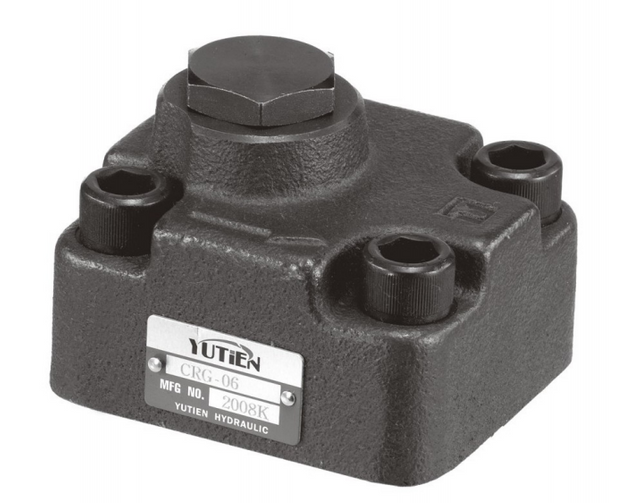
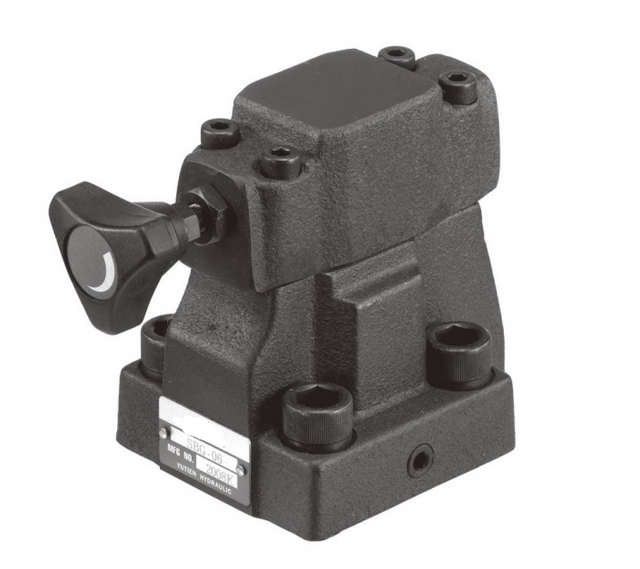
Hydraulic pressure control valves do four common jobs. A relief valve limits pressure in a line by opening a path for oil to leave it. A reducing valve supplies a branch at a lower pressure. A sequence valve opens a path to a second function when it receives a specified pressure signal. An unloading valve changes a flow path or control signal so a pump or pump stage can operate against a lower pressure. To tell them apart, ask where the valve senses pressure and where the oil goes when the valve changes position.
What a pressure control valve does
Imagine an assembly machine with a clamp and a cylinder that pushes a part into a fixture. The clamp needs enough force to keep the part in place. The work cylinder may need considerably more force. At the end of a stroke, the pressure in the supply line can rise. Each of those conditions can call for a different response from the circuit.
Oil comes from a pump. The pressure at a particular point depends on the load, restrictions and what the pump and its controls are doing. A pressure control valve responds to a pressure signal by opening, restricting or changing a flow path. Some valves sense the pressure where they receive oil. Some sense a branch downstream. Others can respond to a separate signal line. A live pressure reading means more when you can say which part of the circuit it represents.
On a simple drawing, a relief valve may have a connection from the pump line to the tank line. A reducing valve may sit in series with a smaller branch. A sequence valve may send oil to a second function when the first develops a designed pressure. An unloading valve may give a pump a lower-resistance route. Those are useful starting pictures. In a manifold, the same functions may be built into a block with passages that are invisible from the outside. Start with the symbol and the exact assembly code. Bosch Rexroth hydraulic fundamentals and basic circuits
Common valve
What it responds to
What changes in the circuit
A question a buyer can ask
Relief
Pressure in the line being protected in a common arrangement
Oil can leave through a relief path when the opening condition is reached
Where does the oil go at the specified relief flow?
Reducing
Pressure in the branch it supplies in a common arrangement
It restricts incoming flow as the controlled branch approaches its pressure setting
Which branch should operate at the lower pressure?
Sequence
Pressure at an internal or external signal point
A path to a later function becomes available at the designed pressure condition
What pressure signal is intended to permit the second action?
Unloading
A specified sensed pressure or control signal, depending on the design
A pump or pump stage can operate against a lower pressure through a return or control arrangement
When should the pump unload, and what should make it load again?
A pump control or an electronic circuit can perform part of this work. To identify the components on a machine drawing, start with the overview of hydraulic valve families and their functions.
Relief valves limit pressure in the protected line
A relief valve in a simple open circuit connects a supply line to a path that leads toward the tank. During ordinary movement most or all of the intended flow can go to the actuator. If motion stops and a fixed-displacement pump continues to supply oil, pressure can rise. The relief valve can open when its opening condition is reached, allowing oil to flow out of that protected line. The circuit designer selects the relief arrangement for the machine's required flow and acceptable pressures. HydraForce RV10-26 relief valve, operation and tested relief pressure
The term relief setting can refer to a pressure measured under a manufacturer's test conditions. Find the corresponding test flow in the data sheet. The pressure at which a valve begins to pass a small amount of oil and the pressure seen as it passes the required relief flow can differ. A gauge may also register a short transient when motion changes. These are different observations, even when a report labels each of them “the relief pressure.”
Trace the destination of that oil. A return connection can have backpressure. Some valves reference an outlet pressure or have a separate drain, and the effect on the effective opening condition depends on the design. The pressure seen at the pump can also differ from the pressure at the valve or at a remote actuator. If there is a disagreement between a measured reading and the expected relief behavior, identify the measurement point and the state of the machine first. BLINCE guide to pressure gauge placement and test points
A fixed pump passing much of its delivery through a relief path can turn hydraulic power into heat. This can happen while a machine is stalled or while a circuit holds pressure in a way the designer did not intend for sustained use. An occasional peak and an extended period of bypassing oil call for different reviews. A replacement valve should be checked at the flow and duty it must handle. A higher printed rating alone gives little information about how that machine will behave.
Relief valves can also be used near an actuator to handle conditions local to that branch. A motor running under changing loads or a cylinder with a trapped volume can see pressure events that the main supply gauge misses. A machine with a local relief arrangement requires its own diagram, valve data and return or cross-port specification. One manufacturer's pump relief cartridge does not necessarily serve the same job in a motor cross-port circuit. The RV10-26 documentation, for example, identifies limitations on the positions and applications for that particular series.
Reducing valves supply a lower-pressure branch
Picture the clamp again. The main line supplies a work cylinder that needs more force. The clamp receives oil through a reducing valve so it can work at a lower pressure. In a common arrangement, the reducer senses the downstream side and restricts the inlet path as the branch reaches the intended pressure. The main circuit can continue to operate at a higher pressure when another load requires it. HydraForce HVPR10-E48 pressure reducing and relieving valve
The setting describes the lower-pressure branch. A reducer needs enough upstream pressure and flow to supply that branch. If the upstream pressure is already below the intended branch pressure, the valve cannot make up the difference. As the clamp moves, it also needs enough oil to reach the required speed. A pressure figure measured while the clamp is stationary does not establish how much flow the valve can pass while the cylinder is moving.
A pressure reducing valve and a pressure reducing and relieving valve have related names. The difference matters when an outside load raises the pressure in the lower-pressure branch. A reducing-only function can restrict incoming flow. A reducing and relieving design can also open a path for downstream oil to leave under the conditions specified for that valve. Find this function on the exact symbol. The drain or relief connection has limits of its own, and the actual discharge path must be compatible with the circuit.
Look for reverse flow as well. A branch may receive oil through the reducer while the cylinder moves one way and then need a separate or built-in route as it returns. A check valve can serve that purpose in some arrangements. A label such as “reducing valve with check” should prompt a look at which way the check opens and where the reduced pressure is measured.
A clamp example to show why the branch matters
Suppose the common supply is at 140 bar while a work cylinder is moving. A separate clamp branch is supplied at about 60 bar under its stated operating condition. The two readings can exist at the same time at different points in the same machine.
If the clamp uses a 40 mm bore and applies pressure to the full piston area, the area is about 1,257 mm². With negligible pressure on the opposite side and ignoring friction, 60 bar produces about 7.5 kN of cylinder force. The same calculation at 140 bar gives approximately 17.6 kN. These illustrative forces apply at the piston, before any linkage. Use the machine’s specified operating conditions to determine the required branch pressure. The drawing and real load determine the force at the part. A quote for a reducer should name the location of the desired pressure and the flow required while it is delivering oil.
An order can call for a new regulator because a workpiece is changing or because the equipment is being duplicated. Ask for the desired force and motion before deciding what the branch needs. Two clamps can have the same pressure and apply different force if their cylinder areas differ. Two parts with the same force requirement can still require different clamp geometry or timing. Record the machine requirement and the hydraulic readings in separate lines.
Sequence valves use pressure to allow the next action
Some circuits use pressure to decide when another function can receive oil. Consider a fixture meant to clamp before a work cylinder moves. Once resistance at the clamp raises the sensed pressure to the opening condition, a sequence valve can open a path to the next actuator. The precise signal, main ports and drain are part of the circuit design and the chosen valve. An externally piloted model can use a pressure from a separate part of the machine. HAWE manufacturer glossary on pressure switching valves · HydraForce externally piloted sequence valve example
The pressure tells the valve that its hydraulic condition has been satisfied. By itself, that signal does not establish where a cylinder is in its stroke. A restriction or a jam can raise pressure before the clamp reaches its intended position. If the machine depends on position, part presence or another condition, check how that condition is verified in the equipment design. A pressure sequence valve should be evaluated along with the machine's control and guarding arrangements.
Sequence pressure can also be affected by where a valve's spring chamber drains and by the pressures seen at its ports. Replacing a valve with a similar body can change whether the opening condition still represents the first function. Ask for the old symbol, the intended first and second actions and the pressure measurement location. Ask whether either actuator needs a free return route and which component provides it.
Write out the cycle when requesting a quote. For example, describe the clamp moving into contact, what confirms the required condition, what the work cylinder can do next and how both functions return. An order with only a part number and a pressure setting gives the supplier little information if the existing valve is obsolete or its suffix cannot be read. A short sequence with the expected movement and signal can clarify the replacement without guessing the circuit.
Unloading valves change the pump's work during part of the cycle
A simple relief path can divert oil while pressure is high. An unloading arrangement is intended to let the relevant pump or stage run at a lower pressure during part of the machine cycle. A hydraulic accumulator system is one example. An accumulator can store energy, and a designed circuit can stop charging it at a specified sensed pressure and start charging it again at a lower pressure. A check or other circuit element can isolate the charged side while the pump or control signal unloads, depending on the design. HydraForce technical bulletin on accumulator charging and unloading
A second example can be found in machines that use a high-flow, lower-pressure stage for rapid approach and another stage for higher-pressure work. When the load increases, a properly designed unloading arrangement can remove the first stage from the high-pressure job. The change should match the equipment's flow paths and pressure limits. A buying brief should identify which stage is being unloaded and where its flow goes after the change.
A reading on the pressure side of an accumulator can stay high while the upstream pump side sees a much lower pressure. This makes sense once the points are named. To compare two quotes, locate the signal pressure that triggers unloading, the pressure range for returning to the loaded state, and the flow or signal line handled by the exact part. Some unloading cartridges pilot another component and are rated for a small control flow. They do not necessarily carry the full pump delivery. HydraForce UP10-40 product data, pilot unloading and reload conditions
A long quiet period with the pump on may be a normal part of the duty. The useful question is what the pump is doing during that time. Does a designed path let its output circulate at relatively low pressure? Does its displacement control reduce delivery? Does the pressure stay high because a relief valve is passing flow? The same phrase “runs in standby” can describe different energy use. The machine drawing and measurements establish which explanation fits.
Read the drawing by following the pressure signal
A valve symbol gives you the first set of answers. Find the line whose pressure is controlled, the line the valve senses and the path that opens or changes. A pressure signal connected through a small passage can come from a different place than the oil passing through the main openings. Outside a manifold it may appear as a separate hose. Inside a block it may be a drilled passage with no separate fitting. A valve's position in a photograph may therefore be less informative than its symbol.
Read the port notes in the model data sheet. An upper working pressure for one port does not automatically apply to the drain or outlet. A catalog number can identify the same visible housing with a different spring range, pilot reference or flow direction. If a valve's condition depends on a separate drain, record where that connection goes and the expected backpressure. If it depends on a pilot signal, record what feeds that signal and during which part of the cycle it changes.
On the drawing or data sheet
What to copy into the comparison
Main inlet and outlet
Port identifiers, normal flow direction and what the ports connect to
Pressure sensing point
Inlet, outlet or separate pilot source, with the valve state that should follow it
Drain or vent
Port number and circuit destination, permissible pressure and oil conditions
Set pressure and definition
Test flow and other test conditions, whether the figure represents opening, regulated pressure or a switching value
Return and reverse flow
What happens when the actuator returns or a load drives oil back toward the valve
Valve mounting
Cartridge cavity, subplate or stack pattern, together with seal and port arrangement
Now read the machine drawing again for the job it must do. A pressure control product can be part of a directional valve bank or a power unit. The whole assembly may have separate settings for supply protection, branch pressure or a local function. Two cartridges that physically fit a cavity can have different symbols and produce different behavior during the machine cycle. For an existing assembly, get the full cavity and part information before treating either part as a candidate.
Put working pressure, valve setting and component rating on separate lines
A working pressure refers to a measured or specified operating point. It may change while an actuator moves or as the load changes. A valve setting describes the pressure condition used to regulate or switch a particular function, often with a test flow attached. A pressure rating describes a component limit under stated conditions. Keep those three numbers separate in a purchase request. It prevents a maximum body rating from being read as the pressure the machine ought to run at.
For a hypothetical circuit, a 140 bar supply reading observed in one moving state is a working measurement. A request to regulate a clamp branch around 60 bar describes a desired controlled pressure. The maximum working pressure printed on a candidate valve belongs to that product's stated operating limit. Add the required flow, oil condition and the state of each port. A quote that gives only “a 140 bar valve” leaves out whether 140 bar is a supply reading, a control setting or a limit.
Some data sheets also list proof pressure and burst pressure. These describe different test or failure conditions from the published working rating. Read the meaning used by the manufacturer and use the working limits for normal operation. Continuous and intermittent conditions may have their own requirements. With a new circuit, check the connected hose, fittings and actuator limits as well as the valve, since all see the circuit's operating pressures in their own locations.
Flow rate belongs on the same note. A relief path can need to handle much more oil than the pilot line that controls it. A reducing valve can behave differently under a low-flow test and when the branch is moving at its normal speed. If a manufacturer gives a pressure-flow curve, read the point matching the application along with the temperature, pressure reference and fluid details. Ask the supplier how the selected valve is expected to work at that point and during relevant repeated operations.
Work out which pressure drop is making heat
Hydraulic power passing through a pressure drop can be estimated by multiplying the flow in litres per minute by the drop in bar and dividing by 600. The result is in kilowatts. This is a useful estimate for sustained flow through a restriction, with upstream and downstream pressures referenced the same way. It does not tell you the heating contribution from other branches, pumps or mechanical losses.
Suppose 20 L/min returns through a relief path while the inlet is at 140 bar and the return is at 5 bar. The 135 bar drop represents about 4.5 kW of hydraulic power being dissipated in that example path. In another state, 6 L/min through a reducing path from 140 to 60 bar represents 0.8 kW. Those are independent illustrations. Only measured or documented simultaneous flows can be combined to describe an actual machine. Bosch Rexroth hydraulic fundamentals reference
A return line that gets warm can be useful evidence when it is marked on the drawing and linked to a known machine state. Oil mixes as it goes through the system, so temperature alone cannot assign the heat to one valve. Ask which path was carrying flow, how long that state lasted and what the pressures were at both ends. Use the approved test procedure and the equipment's actual operating limits.
What to record when a machine behaves differently
Start with the action you can see. Is the whole machine weak, does only the low-pressure branch lose force, does the second action start early, or does the pump stay loaded between cycles? Each describes a different state and a different next question. If the original symptom appears only once the oil is warm, say how long the machine ran before it appeared. A cold reading and a warm reading can be useful where both belong to the same commanded function.
If the pump shows normal pressure while an actuator lacks power, match your measurements to the path carrying oil at that moment. A gauge upstream of a valve cannot describe all the conditions downstream. If a sequence valve appears to open too early, identify the actual pressure at its sensing point and compare it with where the first actuator was in its motion. Ask a service technician to use the manufacturer’s procedure for any measurements that involve live pressure or a supported load.
Observed condition
Detail that helps the supplier or service team
Pressure rises when the actuator stops
Gauge location, machine command, time at that condition and designed oil path during the stop
Low-pressure branch gives less force
Working pressure at the branch, supply pressure, load, cylinder geometry and whether the branch was moving
Second action starts before expected
The position or state of the first action, the signal port and whether the first action was obstructed
System runs hotter between cycles
Duration of standby, which pump is operating and which return path the design uses in this phase
Replacement has a different connection or suffix
Both complete model codes and the drawings with the relevant ports marked
Where the equipment uses a liquid-filled hydraulic pressure gauge, the correct gauge range, installation and response still depend on what needs to be measured. A steady gauge indication can be useful for the running condition. A short transient may require different equipment and a documented test method. The gauge should be considered part of the evidence you collect, alongside the diagram and operating state.
What to send before ordering a pressure control valve
Label the job in ordinary language first. A note such as “keep this clamp branch at the specified lower pressure while the main system works” helps identify the task. Add the exact valve symbol or send a marked page of the circuit drawing. Mention which part is being replaced if the valve is inside a manifold or valve bank. A code on a complete manifold and a code on a cartridge can identify different things.
Use the BLINCE pressure control valve range to find the relevant product group. If the valve is part of an assembly with several functions, the wider hydraulic valve catalog can help identify the type of component before confirming the variant. Ask for a drawing and working data for the exact candidate. The family page is a starting point for that conversation.
For a replacement, give the existing model identification, mounting or cavity, expected flow and pressures, and the ports used as pilot, drain or return. Record how oil moves backwards or out of the branch if that matters. For a new machine, give the sequence of actions and the pressure or movement each branch needs to produce at the intended duty. Include temperature and fluid information when it affects performance or seal choice.
Contact BLINCE with your schematic, existing part code where available and the function you need to control. A good initial comparison identifies a candidate family, checks the mounting and the specified port behavior, and shows which data still need confirming for a quotation.
Common questions about pressure control valves
Can one valve replace another if both list the same bar rating?
A matching figure is a starting point. Confirm what it measures, which port it belongs to and what the valve does when the condition is reached. A relief valve set to open at a given pressure and a reducing valve intended to regulate a branch near that pressure perform different jobs. Compare the symbol, test flow, pilot and drain before selecting a replacement.
Does a sequence valve tell the machine that a cylinder reached the end?
It tells the circuit that the specified pressure signal was reached at the sensing point. The pressure can change for other reasons, including an obstruction. For a machine that requires a verified position before the next action, use the sequence and position verification specified by the machine designer.
Why would a pump unload when the machine still has pressure?
The pump and the part of the circuit storing or holding pressure can be separated by a designed valve arrangement. The pressure gauge at the accumulator or load may still indicate pressure while the pump works against a lower pressure. Name the two measurement points and identify the loading and unloading states on the drawing.
Can a pressure reducing valve set the speed of an actuator?
It regulates pressure at the specified point. Speed depends mainly on the flow available to the actuator and its displacement or area, with the circuit and load adding conditions. If the machine needs a slower motion and the force requirement stays the same, identify how the equipment controls flow before choosing a different valve.
What should I ask for when there is no readable valve code?
Ask for the circuit symbol and a dimensioned view of the manifold or mount. Share the machine model, the function and pressure state the valve serves, and clear photos of the component and its connections. The supplier can use the information to narrow the task and tell you whether a matched drawing or original equipment record is needed.
This article is a general engineering guide. Final component selection should be based on machine drawings, measured hydraulic data, working conditions, safety requirements, and confirmation from a qualified hydraulic engineer or supplier.
Blince Hydraulic Team
Blince Hydraulic is an industry-leading company dedicated to precision-engineered fluid power manufacturing and custom hydraulic solutions. Backed by decades of deep field expertise in industrial machinery and thousands of successful global deployments, our engineering team focuses entirely on high-performance hydraulic component manufacturing, including specialized orbital motors, high-pressure travel drives motor, and robust directional control valves. Our production infrastructure utilizes state-of-the-art multi-axis CNC machining systems and is fully ISO 9001 certified to guarantee repeatable volumetric accuracy across every single manufacturing run.
We deliver fast, highly dependable, and cost-efficient hydraulic solutions to heavy industry distributors, machinery OEMs, and maintenance crews across more than 150 countries. Whether your active project calls for a small-volume batch of customized shaft profiles or a large-scale production run of severe-duty cast iron gear pump, we configure our flexible production schedules to meet your target lead times with total pricing predictability. Partnering with Blince means securing maximum system efficiency, elite material quality, and uncompromised fluid power professionalism.
To learn more about our complete product lineup, visit our official website: www.blince.com.