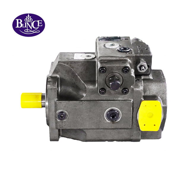
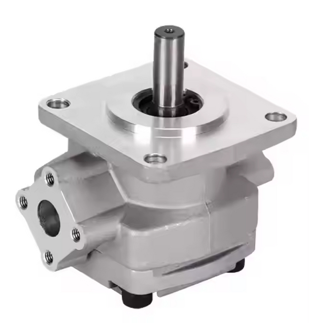
A machine may already have a VQ-style pump that bolts neatly to its drive. Its operator wants a faster cylinder, so a larger displacement code looks like an easy upgrade. The flange can remain familiar while extra oil demands more shaft power, changes inlet velocity and sends unused flow across a valve. A replacement buyer faces another trap: copying a partial “25VQ” label without identifying the old assembly's displacement, shaft, rotation and port arrangement.
Short answer. Start a 25VQ selection with the required delivered flow at the machine's actual pump speed and warm working pressure. Use the published displacement table to identify a candidate, then confirm its pressure and speed limits, inlet condition, drive capacity and complete installation code against the current approved drawing. A family name or a matching flange alone cannot establish an interchangeable replacement.
This guide addresses one decision: whether a particular 25VQ configuration can supply the required machine motion without exceeding the drive or installation boundary. It does not turn a flow estimate into a performance guarantee. If the symptom is declining flow on an existing pump, diagnose the circuit before treating a larger unit as the answer.
Evidence boundary: what the public data establishes
The BLINCE V/VQ product page identifies 25VQ as part of its vane-pump range and publishes displacement rows for codes 10, 12, 14, 15, 17, 19 and 21. It also contains model-dependent pressure and speed cells. Because the web table's merged cells are not consistently clear in extracted text, obtain the current series sheet for the exact code before approving continuous pressure or maximum speed. The vane-pump category helps establish the commercial family, but it is not a substitute for a dimensioned installation drawing.
Two manufacturer documents help explain the method without proving parts interchangeability. Vickers by Danfoss publishes a 25/26/30/31 VQ service and parts manual, including a 25VQ model-code context and cartridge construction. Parker's overall vane-pump instructions describe installation, inlet, rotation and troubleshooting checks for its own T-series pumps. These documents are technical references, not BLINCE ratings or permission to fit a Danfoss or Parker cartridge into a BLINCE assembly. The 20VQ parts and repair guide makes the same distinction for the neighboring size, while the vane-pump principle guide explains the mechanism without claiming cross-brand parts fit. An accurate family drawing can still be the wrong drawing for the installed unit.
All operating numbers in the worked example below are Example inputs unless identified as Published BLINCE displacement values. Calculated results describe an assumed circuit. Actual delivered flow, efficiency, allowable inlet condition, pressure duty, shaft loading, dimensions and parts compatibility remain Unknown—confirm by the exact data sheet or measurement. Keep those labels attached to the decision rather than treating arithmetic as a test result.
First separate the machine's required flow from the old pump code
For a new build, record the actuator motion that matters: cylinder speed over the working stroke, motor speed under load, or the time available for an approach movement. Establish the flow at the actuator, then allow for the actual valve path and any simultaneous functions. The pump-flow calculation guide explains the displacement-to-flow relationship; the pressure-gauge placement guide shows why a pump outlet reading alone does not describe the actuator's condition. Record the points and operating state together, because a number without its location can send the sizing discussion toward the wrong component.
For a replacement, first ask why a change is proposed. Was the original machine always too slow, or did it lose speed after warm-up? If performance fell over time, measure pump shaft speed, outlet flow at the relevant working pressure, oil temperature and the pressure drop through the active valve path. A vane-pump noise and flow-loss diagnosis is more relevant when the old unit whines or delivers less oil hot than cold, while the contamination-control guide helps evaluate whether debris or oil condition will damage the replacement. A larger displacement will not repair an obstructed inlet, leaking valve or worn actuator.
Replacing a worn 25VQ with the correct configuration aims to restore the machine's original duty. Upsizing changes that duty. It requires new checks for motor input, suction line, relief capacity, valve flow rating, return line, cooler and motion control. Put the existing baseline next to the desired motion before choosing a code; otherwise the supplier cannot tell a like-for-like request from a circuit redesign.
Decode the 25VQ designation before comparing catalog numbers
“25VQ” identifies a size family, not a complete orderable assembly. The public BLINCE page lists displacement codes and nominal volume per revolution: code 10 at 32.5 mL/rev, 12 at 38.3, 14 at 43.3, 15 at 47.3, 17 at 52.5, 19 at 60 and 21 at 65. Those are Published rows, not measured output at a stated pressure. The hydraulic pump parts guide provides the rotor, vane, side-plate and housing vocabulary; the VQ family product listing is the starting point for the actual BLINCE code. Request the complete code, nameplate and assembly drawing before assigning a cartridge, seal kit or mounting arrangement.
The purchaser also needs the viewing convention for rotation, shaft extension, flange pilot and bolt pattern, inlet and outlet positions, port sizes and seal material. A photograph of the pump's front face often hides the outlet orientation; a photograph of the old shaft can omit the pilot depth and coupling engagement. If another brand's code appears on the nameplate, do not equate matching numerals with parts interchangeability. The Vickers by Danfoss 25VQ manual describes its own design and service kits; supplier approval must identify which parts, if any, are interchangeable with the requested BLINCE configuration.
Work the flow and power calculation before picking code 17
Consider an Example industrial power unit with a measured pump shaft speed of 1,450 rev/min. The process needs 68 L/min delivered to the circuit at warm oil and its normal loaded condition. Assume 0.90 volumetric efficiency only as a preliminary sizing factor; it is not a published BLINCE 25VQ efficiency value. The geometric displacement required by that assumption is:
BLINCE lists 25VQ code 17 at 52.5 mL/rev. Its theoretical flow at 1,450 rev/min is 52.5 × 1450 / 1000 = 76.125 L/min. Under the example's assumed 0.90 volumetric efficiency, estimated delivered flow is 76.125 × 0.90 = 68.51 L/min. The margin over the 68 L/min requirement is only 0.51 L/min in this calculation. That small difference is a reason to request an actual flow-versus-pressure curve or a controlled warm-oil test, not a reason to promise that code 17 will meet the duty.
Now suppose the same Example working point is 150 bar at the pump outlet. Estimated hydraulic output is P_h = p × Q / 600 = 150 bar × 68.51 L/min / 600 = 17.13 kW. If the preliminary overall efficiency assumption is 0.85, estimated shaft input is 17.13 / 0.85 = 20.15 kW. The 0.85 assumption is a worksheet value, not a BLINCE test result. A 15 kW motor is therefore an implausible drive for this example at that duty; a larger nameplate motor is still not an automatic approval because start-up, peak pressure, duty time, service factor, coupling torque and electrical supply need review. The pump-motor matching guide provides the broader drive check, and the pump-flow calculation guide keeps theoretical and delivered flow separate.
The same calculation exposes why “go one code larger” is not a free safety margin. Code 19 is published at 60 mL/rev; at the same shaft speed its geometric delivery is 87 L/min, 10.875 L/min above code 17's geometric output. If that extra oil is bypassed during a 150 bar working state, the idealized hydraulic power crossing the restriction is 150 × 10.875 / 600 = 2.72 kW. The circuit may not actually bypass that exact quantity; losses, control state and load vary. But the arithmetic makes the next action clear: check the valve route and cooler duty before buying displacement to solve an unmeasured speed complaint.
Use a decision table to turn observations into a candidate route
The table is a screening tool. It links the buying choice to the measurement that could reverse it; none of its rows grants a pressure or interchangeability rating.
Machine evidence
Candidate direction
Benefit sought
Cost or failure risk
Confirm before quotation
Required warm flow is near code 17's calculated delivery and the drive has verified headroom
Evaluate 25VQ-17
Meets the intended motion without unnecessary geometric flow
Assumed efficiency may be optimistic at working pressure
Measured shaft speed, warm loaded flow, current model curve and continuous duty
Existing pump has correct historical speed but now loses flow hot
Diagnose before changing code
Avoids oversizing a worn or starved circuit
A bigger pump may repeat damage or add heat
Inlet condition, oil temperature, loaded flow, valve and actuator leakage
Flow demand exceeds 25VQ-17 and the machine has a suitable drive and inlet
Compare a larger 25VQ code or another family
Faster motion where the circuit needs it
More input torque, inlet demand and possible bypass heat
Full pressure cycle, motor power, suction design, valve and return ratings
Only a second simultaneous function needs more flow
Review a multiple-pump or circuit option
Separates branch duties
Shared drive and inlet may still be overloaded
Each branch's pressure and flow during simultaneous operation
Existing shaft, pilot, ports or rotation cannot be verified
Pause the order
Prevents an attractive but unusable replacement
Installation delay while data are gathered
Complete code, drawing, dimensioned photos and rotation convention
Read across the row that matches the measured condition, then request the last-column evidence. If the machine has a 20VQ and the proposal is to step to 25VQ, compare more than the numerical family label. The 20VQ assembly guide addresses what a parts drawing can and cannot prove; the tandem-pump selection guide is useful when the actual problem belongs to two branches on one drive. The right solution may be a circuit change rather than a larger single pump.
Pressure and speed: identify the duty, then confirm the exact limit
The BLINCE product page describes the V/VQ family as high-pressure vane pumps and shows a family headline up to 21 MPa. Its model table also has different pressure and speed entries across sizes and codes. A family maximum is therefore an identification clue, not an all-day approval for every 25VQ configuration. Record continuous loaded pressure, intermittent events, peak transients, time at each state and where each reading was taken. The pressure test-point guide helps specify the actual gauge positions, while the oil-viscosity guide explains why the same machine can behave differently at cold start and hot duty. Obtain an approved code-specific pressure and speed sheet before committing to either limit.
Shaft speed needs the same care. The electric motor nameplate may state synchronous or nominal rpm, while the pump's actual loaded shaft speed can differ. A belt or gearbox adds another ratio; an engine-driven PTO can change speed during the work cycle. Measure or calculate the drive speed at the operating state that defines required flow, and document minimum and maximum. A higher pump speed raises flow but also raises inlet demand and may reduce available margin to the series speed limit. If the high-speed pump comparison leads back to rpm, repeat the power and inlet checks before accepting the change; the coupling-alignment guide addresses the drive interface that must carry it.
The inlet and oil can disqualify an otherwise plausible code
A fixed-displacement vane pump must fill its chambers on every revolution. A 25VQ that needs more oil per turn can expose a narrow suction hose, long run, dirty strainer, closed valve, low tank level or cold viscous oil that the old arrangement tolerated. Measure inlet pressure or vacuum at the pump under the relevant flow and temperature, then compare with the exact manufacturer's allowable condition. The vane-pump noise and flow-loss guide separates starvation clues from internal wear, while the oil-viscosity guide helps explain why cold and hot observations can point in different directions. Do not treat a quiet no-load run as proof that the inlet works at full flow.
The oil route also matters after a failed pump. Debris can remain in a reservoir, filter housing, return line or valve block and damage the next cartridge. Identify the failure material and the cleaning method before installing a replacement. Parker's vane-pump troubleshooting instructions list inlet supply, air entry, viscosity, rotation and relief behavior as separate checks. Those principles support the BLINCE contamination-control path; the pump-parts guide helps identify which removed surfaces and components should be documented. Parker's installation limits still belong to Parker models. Select filtration and startup method from the actual circuit and current 25VQ documentation.
Interfaces: a “fits the flange” claim must survive the full drawing
Put the old and candidate pump drawings side by side. Compare pilot diameter and depth, bolt spacing, shaft diameter and form, key or spline engagement, coupling gap, rotation viewed from the specified end, port thread and seal form, inlet and outlet positions, overall envelope and clearance for service. A coupling can engage just enough to turn a new pump during a short test while carrying load on the wrong portion of the shaft. The coupling-alignment guide shows why geometry and pipe strain matter after assembly; the 20VQ assembly guide illustrates why a parts drawing cannot settle installed-unit compatibility on its own. Record which dimensions were measured and which remain supplier-confirmed.
Port orientation deserves an annotated photograph. A replacement may place the pressure port where the old inlet hose ran, or require a tight adapter that restricts the line and pulls on the housing. If the available envelope makes the specified suction line impossible to route without a sharp bend, the mounting match is not enough. The double VQ product page shows why section combinations add another layer of port identification; the tandem-pump guide explains why two outlets need separate duty records. Never infer a dual-pump configuration from the single 25VQ table.
Tradeoffs that change the selection
Flow margin brings a drive and inlet burden. A larger code can reduce the chance that a conservative efficiency assumption leaves the actuator short of speed. It also raises geometric flow every time the shaft turns. If the machine spends much of its cycle throttling or bypassing the extra oil, temperature and power draw can increase. The pump-motor matching guide supports the torque and heat review, and the pump-flow guide keeps the displacement comparison in common units. Measure the cycle before spending money on the larger code.
A matching 25VQ configuration may minimize mechanical and commissioning changes when the original circuit was sound. A different displacement, different pump family or a dual-pump solution can better serve a changed duty, but it also changes valve flow, inlet demand, return capacity, heat rejection and documentation. The vane-versus-gear comparison helps frame a technology change, while the vane-pump category identifies the BLINCE product routes to review. Do not write “equivalent” on an RFQ until both the interfaces and the operating states match.
Equipment checks before a purchase order
On an industrial power unit, collect the drive nameplate and, if possible, loaded electrical current or motor speed during the same state as the hydraulic measurements. Note relief settings, spool position, whether the machine holds pressure at zero actuator motion, and how long it remains there. The pressure-gauge placement guide can guide measurement locations; the pump-motor matching guide provides the drive-power context. A code that looks adequate from cylinder speed alone can still be wrong for a long high-pressure hold.
On mobile equipment, include idle and working engine speed, cold-start temperature, shock events, reservoir level during slope operation and any steering or pilot demand that overlaps the main function. A pump that works at steady workshop rpm may be starved at high engine speed or slow at an idling work point. The oil-viscosity guide supports the temperature check, and the high-speed pump article gives a broader rpm-versus-displacement decision. The exact machine manual determines safe test states and permissible modifications.
If the 25VQ is part of a multiple-pump assembly, record each section's code and outlet, which functions can work together, common-inlet dimensions and shared shaft loading. A single outlet pressure reading cannot represent the whole drive. The double VQ listing establishes that combined configurations are offered; the tandem selection guide shows how simultaneous flow and power change the review. Confirm the actual combination drawing instead of adding two catalog headline values.
Common ordering mistakes and their consequences
One common mistake is using the displacement code as delivered flow. Code 17's 52.5 mL/rev establishes a geometric volume, not a guaranteed 76.125 L/min at 1,450 rpm under pressure. Leakage and drive speed change the result. Another is assuming the largest family pressure figure applies to the chosen code throughout the duty cycle. The BLINCE product table is the first identification source; the flow calculation guide shows what still has to be estimated or measured. Ask for code-specific performance and pressure confirmation before comparing quotations.
A second cluster of errors begins at installation: copying the old flange while missing rotation, choosing an adapter from thread diameter alone, forcing rigid pipe onto the pump, or starting before the inlet is filled according to the approved procedure. These mistakes can create noise and seal problems that look like defective manufacture. The coupling guide and vane-pump noise diagnosis direct the investigation toward geometry and inlet conditions. Preserve the old unit and take photographs before dismantling it if replacement compatibility is uncertain.
The third is treating a weak machine as proof that its pump needs upsizing. A restricted valve, damaged coupler, relief bypass, contaminated oil, slipping drive or leaking actuator can yield the same complaint. Record loaded flow and pressure at named points before the order. The pressure test-point guide and contamination-control guide turn those observations into a better test path. A new pump should be a response to evidence, not the first diagnostic instrument.
When a 25VQ quote should wait
Pause a direct replacement if the complete old code is unreadable, shaft and port drawings are missing, rotation is uncertain, or the pump is being blamed without a warm loaded flow check. Also pause if the requested duty exceeds an unverified continuous pressure or speed limit, if the inlet condition is unknown after cavitation-like symptoms, or if the drive power cannot cover the proposed flow and pressure. The VQ product page identifies available family rows, and the vane-pump flow-loss guide helps identify what to measure next. These gaps are solvable; they should be written into the RFQ rather than silently assumed away.
For personnel lifting, suspended loads, braking or another safety-critical function, component selection belongs within the approved machine architecture and service procedure. Do not alter relief or control settings as a generic sizing experiment. A qualified reviewer needs the circuit drawing, machine manual, failure behavior and exact component documentation before approving the change.
Copyable 25VQ inquiry data
Send a short, structured record rather than “same pump, more flow.”
Machine and function: ; current symptom or new performance target: ; original and candidate full codes: ; old nameplate and port photos: attached/not available. Required warm delivered flow: L/min at bar and °C. Pump shaft speed: rev/min at that state; minimum/maximum: /_ rev/min. Continuous pressure and duration: bar for ; intermittent and measured peak: . Drive motor or PTO rating and measured loaded speed/current: . Oil grade and cold/normal/hot temperatures: ; inlet pressure or vacuum and measurement point: . Rotation viewing end: ; shaft, pilot, flange, ports and envelope drawing: . Relief and valve route: ; filtration and prior failure debris: __.
Where the request is an upgrade, add the required actuator motion and simultaneous functions. Where it is a replacement, add warm versus cold symptoms and the old pump's tested delivery. BLINCE can then compare plausible 25VQ codes, identify the data preventing an interchangeability claim and say whether a circuit or inlet check should come before quotation. No supplier should have to infer those conditions from a cropped photo.
FAQ
Is 25VQ-17 a 17 mL/rev pump?
No. BLINCE's published table associates code 17 with 52.5 mL/rev. The number in the code is not itself the metric displacement. Confirm the full model designation before ordering.
Can I use a 25VQ in place of a 20VQ?
Possibly, but the family-number change does not prove mechanical or hydraulic compatibility. Compare complete drawings, shaft and coupling, rotation, ports, inlet capacity, flow, pressure duty and drive power. Treat an upsizing request as a machine change.
Does a larger displacement always speed up the cylinder?
Only if the drive can turn it at the required speed, the inlet can fill it and the circuit sends the added flow to the cylinder. Relief bypass, valve restriction or another simultaneous function can consume the expected gain.
Can the published 21 MPa family maximum be used continuously?
Do not assume so. The current family page contains model-dependent entries. Obtain the current approved sheet for the exact 25VQ code and record continuous, intermittent and peak duty separately.
What is the minimum useful test before ordering a replacement?
Capture the complete model code and interfaces, then record pump speed, inlet condition, warm loaded outlet flow, outlet pressure and oil temperature in the state that fails. Add downstream pressure where the complaint concerns actuator performance.
Does the Vickers by Danfoss 25VQ manual prove BLINCE parts interchangeability?
No. It explains a manufacturer's VQ construction and model coding. An approved BLINCE drawing and supplier confirmation must establish the proposed part or assembly match.
Engineering handoff
Send BLINCE the complete old code, machine function, required warm flow, actual pump rpm, measured pressure duty, oil temperature, inlet condition, drive rating and dimensioned interface evidence. BLINCE can return a candidate code direction, the missing confirmation points and whether the pump order should wait for a drive, inlet or circuit correction.
This article is a general engineering guide. Final component selection should be based on machine drawings, measured hydraulic data, working conditions, safety requirements, and confirmation from a qualified hydraulic engineer or supplier.
Blince Hydraulic Team
Blince Hydraulic is an industry-leading company dedicated to precision-engineered fluid power manufacturing and custom hydraulic solutions. Backed by decades of deep field expertise in industrial machinery and thousands of successful global deployments, our engineering team focuses entirely on high-performance hydraulic component manufacturing, including specialized orbital motors, high-pressure travel drives motor, and robust directional control valves. Our production infrastructure utilizes state-of-the-art multi-axis CNC machining systems and is fully ISO 9001 certified to guarantee repeatable volumetric accuracy across every single manufacturing run.
We deliver fast, highly dependable, and cost-efficient hydraulic solutions to heavy industry distributors, machinery OEMs, and maintenance crews across more than 150 countries. Whether your active project calls for a small-volume batch of customized shaft profiles or a large-scale production run of severe-duty cast iron gear pump, we configure our flexible production schedules to meet your target lead times with total pricing predictability. Partnering with Blince means securing maximum system efficiency, elite material quality, and uncompromised fluid power professionalism.
To learn more about our complete product lineup, visit our official website: www.blince.com.