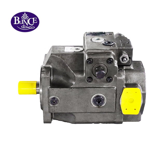
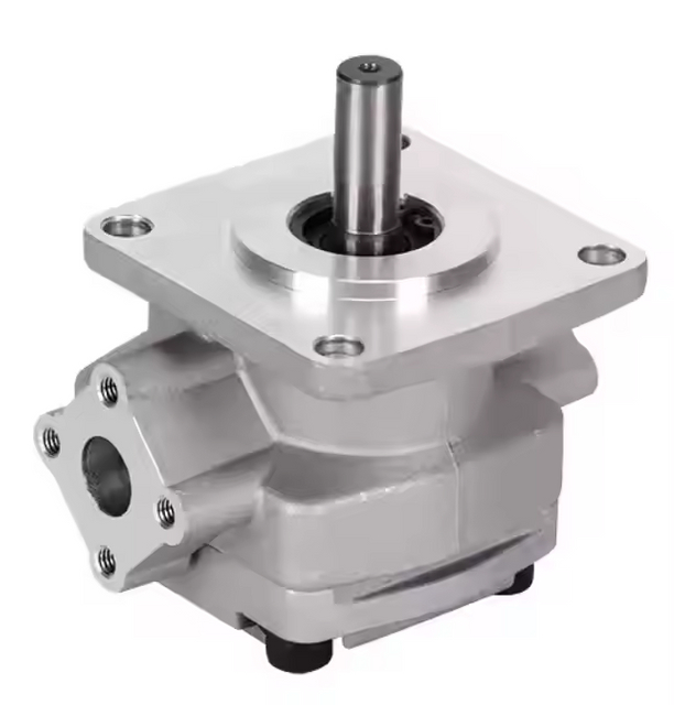
A parts diagram gives names to what a technician sees on the bench: the input shaft, body, gears or other pumping elements, support bushes, side plates, seals and ports. In an external gear pump, the shaft drives one gear and the second gear follows. Oil fills the spaces as the teeth come apart, travels around the casing, then is pushed out when the teeth close again.
That is enough to understand the layout. It is not enough to approve a replacement. A pump can look almost identical and still have the wrong shaft, rotation, displacement or port arrangement. For a real swap, use the maker's drawing and the machine documentation.
How oil moves through a simple external gear pump
Reading it as a flow sequence is usually easier than memorising a list of labels.
Step
What happens
Parts involved
1. Drive
The prime mover turns the input shaft.
Drive shaft, mounting flange, bearing or bushing
2. Draw in oil
The gear teeth separate, increasing the available volume and allowing oil to enter.
Suction inlet, housing, drive gear, idler gear
3. Carry oil
The gears trap oil between their teeth and the housing, carrying it around the outside of the gears.
Drive gear, idler gear, housing, side plates
4. Discharge oil
The teeth mesh again, reducing the trapped volume and sending oil to the pressure line.
Outlet port, gears, side plates, housing
The shaft and flange join the pump to the drive. The body and side plates contain the working chambers. Gears move the oil, while the bushes or bearings keep the shafts located. The seal sits where the shaft comes out of the body.
Actual pumps are less tidy than this sketch. They may have compensation parts, extra sections or separate drain connections. Even within the BLINCE SGP gear-pump range, the displacement and configuration vary. Check the drawing for the exact model.
What a hydraulic pump actually does
An engine, electric motor or PTO turns the pump. The pump sends oil into the circuit. Pressure appears when the circuit resists that flow — perhaps at a loaded cylinder, a hydraulic motor, a narrow valve passage, a dirty filter or the relief valve.
This is why the pump should not be blamed too quickly. A low gauge reading can also come from a relief valve that is opening early, leakage in a cylinder, a worn motor, or a restriction further downstream. The BLINCE hydraulic-pump types guide is useful here: it ties the pump to displacement, speed, oil condition and the rest of the machine.
Most hydraulic pumps on mobile and industrial equipment are positive-displacement designs. Each turn carries a known volume of oil from inlet to outlet. Gear, vane and piston pumps do that job differently, so the internals do not look the same.
Main hydraulic pump components and their jobs
Part
What it does
Why it matters
Drive shaft
Transfers torque into the pump
Key, spline, taper, diameter and length must match the driver
Mounting flange and pilot
Locates the pump on the drive
The correct bolt pattern alone does not guarantee alignment
Housing
Supports internal parts and forms fluid passages
Outside size does not prove displacement or pressure rating
Pumping element
Creates changing volume to move oil
It may be gears, vanes or pistons
Bearings or bushings
Support shafts and control clearance
Wear can increase noise, leakage and shaft movement
Side plates / wear plates
Close pumping chambers at the sides
Their clearance affects volumetric efficiency
Inlet port
Brings oil from the reservoir
Restriction or air entry here can damage the pump
Outlet port
Sends flow to the system
Port size and routing affect pressure drop
Shaft seal
Limits leakage around the drive shaft
A leak can also point to heat or misalignment
Type code
Identifies the exact configuration
It is the best starting point for the right data sheet
Names vary by manufacturer and pump type. A gear pump commonly uses gears, bushings and side plates. A piston pump may have a cylinder block, pistons, valve plate, swash plate and control components. Do not force one diagram's terminology onto every pump.
How an external gear pump works
External gear pumps are common because the mechanism is straightforward. Two externally meshing gears sit inside a close-fitting housing. One gear is driven by the input shaft; its mesh turns the second gear.
Inlet: When teeth separate, the space between teeth and housing increases. This creates a lower-pressure area and oil enters from the reservoir.
Transfer: Oil is trapped in pockets between the gear teeth and housing, then carried around the outer circumference of each gear.
Separation: The point where the gears mesh separates inlet and outlet regions; the main flow does not pass directly through the centre.
Outlet: The teeth mesh again at the outlet. The trapped volume reduces and oil is displaced into the pressure line.
The pump does not create a fixed pressure by itself. With an open outlet it produces flow with little resistance. When it feeds a loaded actuator, pressure rises until the load moves, a valve opens, or a limit is reached. Pressure control therefore belongs to the circuit as well as to the pump selection.
Why internal clearance matters
Every rotating pump needs a small operating clearance for lubrication and movement. The design challenge is to prevent too much oil from leaking internally from the pressure side back to the inlet side.
As parts wear, internal leakage can rise. A machine may work acceptably when oil is cold but slow down when the oil warms and becomes less viscous. That can be consistent with pump wear, but it is not proof: a relief valve, an actuator or a bypassing control valve may cause a similar symptom.
Some gear-pump designs use pressure-related compensation to manage clearance. The published SGP2 information lists axial-clearance compensation and radial hydraulic balance for that series. These are series-specific details; do not assume every gear pump has the same construction.
Do not overlook the inlet port
The inlet is often called the suction port, but it cannot pull oil through any hose arrangement. Oil has to reach it freely and without air leaks. Small hose, a clogged strainer, a soft hose that closes up, very cold oil, excessive lift from the tank or a loose fitting can all starve the inlet.
The first sign may be a harsh sound or unsteady movement. Cavitation is linked to inadequate inlet pressure; aeration means air has entered the oil. A machine can have both. Replacing the pump before inspecting the inlet side is a good way to see the same problem return.
Do not simply increase the fitting size. Look at the complete route: hose length, bends, tank level, oil temperature, strainer condition and the flow the pump is actually trying to draw.
Estimating flow from displacement and speed
Displacement tells you the volume moved in one shaft revolution, usually in cm³/rev or mL/rev. Combine it with rpm and you have a quick theoretical flow estimate:
Calculated example: a 25 cm³/rev pump at 1,800 rpm has theoretical flow of 45 L/min.
25 × 1,800 ÷ 1,000 = 45 L/min
In service, the meter will not show the exact theoretical number. Internal leakage changes with pressure, oil temperature, speed and wear. BLINCE publishes SGP1 examples from 19 to 36 mL/rev, so “SGP pump” by itself does not tell you the flow.
A 32 cm³/rev pump at the same 1,800 rpm would theoretically provide 57.6 L/min. That is not automatically an upgrade. The driver must supply more torque at the same pressure, and unused flow can become heat across a relief path.
Displacement, flow and pressure are not the same thing
Term
Meaning
Example
Displacement
Volume moved per revolution
25 cm³/rev
Flow
Volume delivered per unit time
45 L/min theoretical at 1,800 rpm
Pressure
Resistance to flow in the circuit
Depends on load and restrictions
Torque
Turning force required at the shaft
Rises with pressure and displacement
Power
Rate of energy transfer
Depends mainly on flow, pressure and efficiency
This is why a pump can have a suitable displacement but still be wrong for the application. Pressure duty, speed, drive power, cooling and oil condition must remain inside the selected pump's published limits.
How gear, vane and piston pump diagrams differ
Gear pump
The main pumping elements are gears. The diagram usually shows a housing, drive shaft, driven gear, bushings or bearings, side plates, seals and ports. Gear pumps are often fixed displacement and practical where a compact, straightforward pump is needed.
Vane pump
A vane pump has a rotor with sliding vanes inside a cam ring. As the rotor turns, chamber volume opens and closes. Its parts diagram may show a rotor, vanes, cam ring, side plates and port plate. Vane pumps can suit duties where smooth operation and lower pulsation are important, but oil cleanliness and exact application requirements still matter.
Piston pump
An axial or radial piston pump uses pistons to form pumping chambers. Its diagram can include pistons, a cylinder block, valve plate, swash plate or eccentric mechanism, bearings and control components. It should not be treated as a direct replacement for a gear pump simply because the target flow appears similar.
The BLINCE hydraulic-pump category includes gear, vane and piston families. Use it to understand available types, then use the selected product page and data sheet for a real selection.
How to identify a pump from the diagram and the actual unit
If the old pump is on the bench, start with measurable evidence rather than a visual web search.
Photograph the complete nameplate or stamped code before cleaning it.
Photograph all sides, including ports, arrows and casting marks.
Measure shaft diameter, key or spline, usable length and retaining feature.
Measure the flange pilot, bolt pattern and mounting depth.
Record port type, thread or flange, direction and centre distance.
Confirm rotation using the manufacturer's stated viewing direction, commonly from the shaft end.
Record whether it is a single, tandem or through-drive construction.
Collect normal/peak pressure, required flow, driver speed, oil type, normal temperature and duty cycle.
The first items establish mechanical fit. The final items establish whether the pump will work after it is fitted. Both are necessary.
Five common diagram-reading mistakes
1. Confusing an outlet port with a drain port
Simple gear pumps may have inlet and outlet ports only. Other designs can have case-drain or control ports. Check the exact drawing; do not identify a port from its position on an unrelated image.
2. Guessing rotation
Clockwise and counter-clockwise depend on the viewing direction. Always state the reference, for example “viewed from the shaft end.” A mirrored port layout is not adequate evidence.
3. Estimating displacement from the outside
Gear count, casting size and paint colour do not establish displacement. Use the type code, product data sheet or measured flow under defined conditions.
4. Replacing only the seal after a shaft leak
The seal may be the failed component, but the cause may be shaft wear, bearing movement, coupling misalignment, excessive temperature or fluid incompatibility. Inspect the wider condition first.
5. Treating the pump as the complete circuit
The pump is connected to the reservoir, inlet line, pressure line, relief valve, control valves, actuators, return filter and cooler. Any of these can alter the symptom observed at the pump.
Symptom guide: what to check before ordering a replacement
Symptom
Possible pump-related explanation
Other checks
Whine or growl
Inlet restriction, aeration or wear
Tank level, hose, strainer, fittings, oil viscosity
These are fault-finding leads, not a remote diagnosis. Isolate the machine as required and use suitable test equipment before opening or measuring a pressurised circuit.
When is replacement the sensible option?
Replace a pump when testing shows it no longer meets the machine's required performance within its rated duty, or when the internal damage makes repair poor value. If nobody knows why the previous unit failed, stop there first. A new pump can be damaged by the same underlying fault.
Pause and investigate when there is metal debris in the oil, repeated new-pump failures, a foamy or collapsed inlet line, an unreadable model code, altered driver speed or a changed duty cycle. Installing a clean pump into contaminated oil can create another failure without solving the original problem.
For product orientation, BLINCE supplies SGP hydraulic gear pumps alongside other pump families. Select from the verified model drawing and complete operating data, not an outside photograph alone.
What to send for a replacement quotation
Old model code and nameplate photos
Photos from all sides
Shaft and flange dimensions
Inlet/outlet port specification and direction
Required rotation and viewing convention
Displacement or measured flow requirement
Normal and peak pressure
Driver speed and drive type
Fluid type, normal temperature and contamination history
Application, duty cycle and failure symptoms
BLINCE can use this information to compare a candidate, identify missing details and flag incompatibility risks before quotation. Final approval should always follow the selected product data sheet and the machine's own limits.
FAQ
What are the main parts of a hydraulic gear pump?
Look for the housing, mounting flange, input shaft, drive gear, idler gear, bushes or bearings, side plates, shaft seal and the inlet/outlet ports. The layout changes from one model to another.
What does a shaft seal do?
It keeps oil from escaping where the shaft leaves the pump body. A leaking seal may simply be worn, but look at the shaft surface, alignment, bearing play and oil temperature before fitting another one.
How do I calculate hydraulic pump flow?
Multiply cm³/rev by rpm, then divide by 1,000. That gives theoretical L/min. Test flow will be lower, especially as pressure rises or the oil gets hot.
Is a larger hydraulic pump always better?
No. More displacement raises flow, but it also asks more of the driver and can create relief heat. The circuit decides whether the extra flow is useful.
Can I identify a pump from outside dimensions alone?
No. Outside dimensions do not settle displacement, rotation, shaft style, ports, pressure rating or seals. Find the type code and the matching drawing.
Why does a new hydraulic pump make noise?
Start with the basics: fluid level, inlet line, air leaks, rotation, drive speed, oil viscosity and relief setting. Many noisy new pumps are reacting to the circuit rather than failing internally.
This article is a general engineering guide. Final component selection should be based on machine drawings, measured hydraulic data, working conditions, safety requirements, and confirmation from a qualified hydraulic engineer or supplier.
Blince Hydraulic Team
Blince Hydraulic is an industry-leading company dedicated to precision-engineered fluid power manufacturing and custom hydraulic solutions. Backed by decades of deep field expertise in industrial machinery and thousands of successful global deployments, our engineering team focuses entirely on high-performance hydraulic component manufacturing, including specialized orbital motors, high-pressure travel drives motor, and robust directional control valves. Our production infrastructure utilizes state-of-the-art multi-axis CNC machining systems and is fully ISO 9001 certified to guarantee repeatable volumetric accuracy across every single manufacturing run.
We deliver fast, highly dependable, and cost-efficient hydraulic solutions to heavy industry distributors, machinery OEMs, and maintenance crews across more than 150 countries. Whether your active project calls for a small-volume batch of customized shaft profiles or a large-scale production run of severe-duty cast iron gear pump, we configure our flexible production schedules to meet your target lead times with total pricing predictability. Partnering with Blince means securing maximum system efficiency, elite material quality, and uncompromised fluid power professionalism.
To learn more about our complete product lineup, visit our official website: www.blince.com.