Consider a retrofit proposal. A fixed-displacement pump turns at 1,800 rpm, and the machine cycle is too slow. Raising the drive to 2,400 rpm appears to offer 33% more flow without changing the flange, shaft or plumbing. On paper, it is the smallest modification.
Now add the conditions that the first proposal left out. The pump whines during a cold start. The electric motor already runs near its loaded current. One quick coupler becomes hot after repeated cycles. The pump outlet gauge reaches the expected pressure, but no one has measured flow at the actuator or pressure at the pump inlet.
The arithmetic may be correct while the purchase decision is still wrong. More rpm asks the same inlet to feed more oil, the same drive to supply more power, and the same valves and return path to pass more flow. A high speed hydraulic pump is therefore a complete operating point, not a pump label.
Short Answer
Increase pump speed only when the exact pump model is approved for the proposed rpm at the required pressure, fluid condition, inlet condition and duty cycle. Confirm that the drive can supply the added power, then measure whether the extra flow reaches the actuator without excessive pressure loss, noise or heat.
Choose a larger displacement at lower rpm when the existing pump cannot run fast enough and the larger pump fits the mounting, torque and inlet requirements. If the machine used to meet its cycle time, diagnose lost delivery or downstream restriction before sizing either option. The BLINCE hydraulic pump range provides several pump architectures, while the pump and motor matching guide shows why useful flow and loaded pressure must be considered together.
Evidence Boundary: What the Numbers Can and Cannot Prove
Three kinds of information appear in this guide. Published values come from a current product page or manufacturer document. Calculated examples show a selection method using stated assumptions. Measured values must come from the actual machine at named test points. A calculated flow is not a BLINCE rating, and a published maximum from another manufacturer cannot approve a BLINCE model.
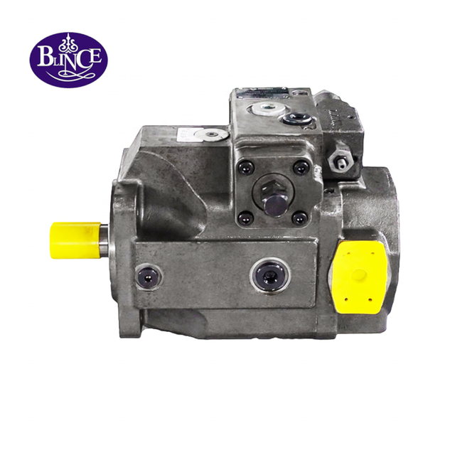
The BLINCE 20VQ–45VQ vane-pump page demonstrates why a series name is insufficient. Its table lists 2,700 r/min for the clear 20VQ 7 mL/rev row, 2,500 r/min for the 35VQ 64 mL/rev row, and 2,400 r/min for the 45VQ 134 mL/rev row. Those entries are useful screening facts. They do not establish one universal VQ speed or prove that pressure, speed, viscosity and continuous duty maxima are simultaneously available.
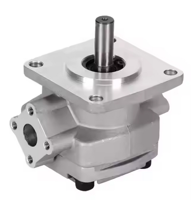
BLINCE also publishes an HGP gear-pump page, confirming a real commercial product family. The public page does not provide the model-specific speed envelope needed for this decision, so that value remains unknown until the complete code and approved data sheet are available. Shaft load, inlet pressure and performance-curve data require the same discipline when a general category page does not publish them.
Manufacturer data reinforces the point without becoming a BLINCE specification. The Parker P1M table lists maximum speed at 1 bar absolute inlet pressure: 3,300 rpm for 28 cm³/rev and 2,600 rpm for 105 cm³/rev. Danfoss GearMe technical information defines maximum speed for a particular pump at rated pressure and notes that minimum operating speed increases as pressure rises. The practical lesson for screening a BLINCE VQ model or requesting the missing HGP operating limits is narrow: read speed, displacement, pressure and inlet conditions as one envelope.
First Decision: Does the Machine Need More Flow, or Has It Lost Flow?
A new design starts with required motion. A machine that has become slow starts with a change history. Mixing those two routes often leads to an unnecessary larger pump.
For a new design, record the actuator speed or cycle-time target, load pressure, simultaneous functions and time spent in each operating state. Rapid approach may need high flow at modest pressure, while the loaded movement needs less flow at higher pressure. A fixed-displacement pump supplies oil whenever it turns, so extra capacity during one movement may become bypass flow during another. The hydraulic matching method connects demand to pump delivery, and the oil-cooler sizing guide helps separate generated heat from heat-rejection capacity.
For a machine that was previously fast enough, repeat the original duty at comparable oil temperature and load. Measure pump-shaft speed, pump outlet pressure, delivered flow and pressure near the actuator. Then note what changed: a hose, coupler, filter, valve, oil grade, reservoir level, drive setting or repair. The pressure test-point guide explains why one gauge cannot represent the entire circuit, while the pump inlet troubleshooting path covers supply faults that can make a serviceable pump appear undersized.
The decision changes with that evidence. If shaft speed and pump outlet flow are lower than the earlier baseline, investigate the drive or pump. If flow leaves the pump but the actuator remains slow, find the downstream loss. If the original machine never met the required cycle, continue to the sizing comparison.
Calculate the Candidate Flow Before Discussing Pump Size
For a fixed-displacement pump, theoretical flow follows displacement and shaft speed:
Qth = Vg × n / 1000Qactual ≈ Vg × n × ηv / 1000Qth, Qactual = flow in L/minVg = displacement in cm³/revn = pump-shaft speed in rpmηv = assumed volumetric efficiency
The second expression is an estimate. Actual volumetric efficiency changes with pump design, clearances, pressure, speed, viscosity and temperature. Use a current performance curve for the final model. The BLINCE pump category can identify a candidate architecture, and pressure readings at defined locations keep measured comparisons tied to the intended duty.
Example 1: Raise a 20 cm³/rev Pump From 1,800 to 2,400 rpm
Assume a 20 cm³/rev pump and a volumetric efficiency of 0.90 at both candidate points. This constant efficiency is an illustration, not a prediction.
The proposed speed rises by 33.3%, and the estimated delivery rises by the same proportion because the example holds efficiency constant. The result answers only one question: 2,400 rpm could produce enough calculated flow if 43.2 L/min meets the machine target. It does not approve the speed or prove that 43.2 L/min will reach the actuator. The next action is to check the exact VQ or other model-specific speed limit and compare the predicted gain with the actual circuit flow requirement.
Example 2: Keep 1,800 rpm and Increase Displacement
Suppose the machine requires 40 L/min and the drive must remain at 1,800 rpm. With the same illustrative 0.90 volumetric efficiency:
About 24.7 cm³/rev is the screening displacement. It is not an order code. The next available catalog size may deliver more than 40 L/min, increase shaft torque, use a different inlet port, or require another flange. Compare the candidate within the current BLINCE pump range, then check whether the existing quick couplers and passages can pass the new operating flow.
Same Flow Does Not Mean the Same Mechanical Load
More useful flow at the same pressure requires more hydraulic power. The drive cannot supply a 33% flow increase under load without a corresponding energy path.
Continue the 43.2 L/min example at a pump pressure difference of 160 bar and assume total pump efficiency of 0.85:
The 13.55 kW figure is mechanical input to the pump. Electric input would be higher because motor and drive losses remain outside this calculation. Before raising speed, compare the required power with the prime mover's continuous and intermittent capability. Then review coupling speed, alignment and allowable shaft load using the pump coupling guidance; if several pump sections work together, add their demands using the tandem-pump selection method.
A larger pump producing the same 43.2 L/min at 1,800 rpm would need about 26.67 cm³/rev under the same 0.90 assumption. At 160 bar and 0.85 total efficiency, shaft power remains about 13.55 kW, but torque rises to roughly 71.9 N·m. Lower speed therefore reduces the rpm requirement while increasing torque at the shaft. The slower option may suit one drive and overload another; check the actual coupling and shaft arrangement and any PTO ratio and rotation constraints before choosing it.
This comparison is the main tradeoff. Higher speed may preserve pump displacement and mounting, but challenges speed approval and inlet filling. More displacement may keep rpm moderate, but increases shaft torque and may change the physical interface. Use the published VQ speed differences and the incomplete public HGP speed information as reminders to obtain the exact model envelope. Neither route reduces the flow that the inlet and downstream circuit must carry.
Follow the Added Flow From the Reservoir to the Return Line
The pump can deliver extra oil only if the inlet supplies it. A suction hose that worked at 32 L/min may create unacceptable restriction at 43 L/min, particularly with cold oil or a low reservoir level. A blocked screen, collapsing liner, tight fitting, partly closed valve or restricted breather can reduce available inlet pressure. Inspect the pump suction path together with the reservoir breather and air path, then measure close to the pump during the condition that produces the largest restriction.
Record inlet pressure during cold start, normal hot operation, maximum requested speed and the lowest permitted oil level. Match the instrument reference to the specification: absolute pressure and gauge pressure are not interchangeable. Use an approved installed test point and the machine procedure; never loosen a live hydraulic connection to create a measurement. The gauge-placement guide supports the measurement plan, and the coupling guide helps separate inlet noise from vibration or misalignment.
After the pump, added flow crosses valves, fittings, hoses and possibly quick couplers. Pressure loss rises with flow according to the component and fluid condition. A thread size that remains unchanged does not prove that the passage is adequate. Measure pressure immediately before and after the suspected restriction and compare the result with the quick-coupler pressure-loss method. Use the pump-to-load matching guide to keep pump outlet flow separate from useful actuator flow.
Unused flow can become heat. If 10 L/min crosses a 160 bar restriction, the theoretical hydraulic loss is:
The value applies only to the stated flow and pressure drop. A properly unloaded path may run at far lower pressure. Locate the loss before increasing cooler capacity: the cooler-sizing process can evaluate heat rejection, while the tandem and simultaneous-demand checks show when several sections contribute to input power or return flow.
Return flow can exceed pump delivery on a cylinder circuit because the two piston areas differ. Combined functions can also send several return streams through one filter or cooler. Measure the actual peak in the relevant direction instead of copying the pump flow into the return-line specification. The pressure-test layout can reveal a restricted return path, and the oil-cooler guide covers the backpressure risk of an undersized cooler.
Choose the Route After the Measurements
Use the following table only after required flow, pressure, duty and current machine condition are known.
Candidate route
Evidence that supports it
Main benefit
Cost or failure risk
Approval data
Increase the existing pump speed
Exact code is approved at the new rpm and pressure; inlet and drive have margin
May retain displacement and mounting
Inlet starvation, noise, bearing/shaft speed limit and added drive power
Model envelope, inlet readings, drive curve, measured flow and duty
Increase displacement at lower rpm
Required flow fits a larger model at the available speed
Avoids an excessive rpm target
Higher shaft torque, larger package, different ports or flange
Performance curve, torque capacity, dimensions and inlet requirement
Restore lost delivery
Machine previously met the target and measurements show a new loss
Recovers performance without increasing nominal pump flow
Diagnosis may uncover more than one restriction or worn component
Before/after flow and pressure, oil temperature and service history
Change pump or control architecture
Demand varies widely across the cycle and unused flow creates loss
Can reduce bypass or throttling during low-demand states
New controls, commissioning and circuit compatibility
Schematic, duty trace, standby state, control logic and validation plan
The table is a routing tool, not a product recommendation. A verified HGP gear-pump configuration may suit a simple fixed-flow duty, while another architecture in the BLINCE pump range may suit changing demand. Installed cost must include drive changes, valves, plumbing, cooling, control work, commissioning and maintenance access—not only the pump quotation.
Machine Details That Can Reverse the Choice
Electric Power Unit
Identify how the proposed speed will be produced. A higher motor nameplate speed, pulley change and variable-frequency drive create different torque, cooling and overspeed questions. Check loaded motor current, allowable torque across the speed range, coupling rating and alignment. The pump-drive matching guide connects power to the hydraulic duty, while the coupling installation guide covers misalignment and external-load risks that higher rpm can aggravate.
Engine or PTO Drive
Calculate actual pump-shaft speed across the full engine range and every gearbox stage. A ratio that supplies enough flow at working speed may overspeed the pump at transport or high-idle speed. Confirm viewing direction for rotation and add simultaneous steering or auxiliary loads. The PTO pump guide provides the ratio checks, and the tandem-pump guide helps when one shaft drives more than one section.
Long Continuous Duty
A short unloaded demonstration cannot approve a production shift. Record stabilized oil temperature, delivered flow, loaded pressure and time spent near each operating point. Check cold startup separately because inlet filling may be worst before the oil warms. The inlet diagnostic guide addresses the cold supply path, and the cooler-sizing guide supports the sustained thermal review.
Purchasing Mistakes and the Evidence That Corrects Them
The maximum-rpm number belongs to the complete operating condition. Buyers often lift one speed from a table because it appears to answer the question directly. A different displacement, inlet pressure or duty can change the limit. Record the full code and obtain the model-specific envelope before treating rpm as approved.
Pressure capacity does not approve speed. A page may publish a high pressure while omitting bearing speed, shaft load or inlet information. The pressure number can screen one requirement, but it cannot fill the missing speed data. The VQ table visibly separates displacement and speed entries, while the HGP page demonstrates why an unpublished rpm remains a quotation question.
A proportional-flow calculation is not a performance curve. The 32.4-to-43.2 L/min example assumes unchanged volumetric efficiency. If inlet filling worsens or leakage changes, measured delivery will differ. Compare flow at the same pressure and temperature, then use defined test locations and the pump inlet checks to explain the difference.
Lower rpm does not remove torque or plumbing limits. The larger-displacement example reduces speed from 2,400 to 1,800 rpm but raises calculated shaft torque from 53.9 to 71.9 N·m at the same flow and pressure assumptions. Both candidates still require 43.2 L/min through the inlet and downstream circuit. Check the coupling load path and the quick-coupler flow path before calling the slower option safer.
A slow actuator does not prove that the pump is too small. If the pump delivers the required flow but a valve, coupler, filter or return path consumes pressure, more nominal pump flow may add heat without restoring useful motion. Measure on both sides of the suspected loss and compare the result with the matching guide and cooler heat-load method.
Who Should Pause Before Ordering
Pause an rpm increase when the complete pump code, approved speed envelope or inlet measurement is missing. The same applies when the prime mover is already overloaded, the pump has unexplained noise, or the machine lost performance without an intentional duty change. These conditions call for measurements before a larger or faster pump.
A larger-displacement order is also premature when shaft torque, coupling capacity, flange, shaft, rotation, ports or installation envelope have not been checked. A pump that meets the flow calculation can still be mechanically incompatible. Review the pump family and interface direction together with the coupling and alignment requirements.
This guide does not approve modifications to steering, personnel lifting, braking or other safety-related functions. A responsible engineer must assess the changed motion, failure behavior and protective architecture using the machine instructions and applicable standards. A generic open-circuit calculation is also insufficient for a closed-loop hydrostatic charge circuit, aircraft system or fluid outside the selected pump's approved specification.
Quote Request Format
Send one package that separates measured values from targets and estimates.
Machine and duty
Machine type and function
Current and required cycle time
Required flow and working/peak pressure
Time at rapid approach, loaded motion, hold, unload and return
Functions that operate simultaneously
Drive
Prime mover type, power and torque data
Minimum, normal and maximum pump-shaft rpm
Gearbox, belt or PTO ratio
Rotation with viewing direction
Coupling, flange, shaft and external-load arrangement
Pump identity
Complete existing model code and displacement
Nameplate and installation photographs
Current approved data sheet, if available
Candidate model or architecture being considered
Oil and inlet
Fluid grade and viscosity data
Cold-start, normal and maximum oil temperature
Inlet pressure at a named point, stating absolute or gauge reference
Reservoir level range, breather, suction hose dimensions, strainer and valves
Circuit and evidence
Hydraulic schematic and control description
Pump-outlet, actuator and return pressure measurements
Flow measurement point and method
Valve, coupler, filter and cooler data
Recent repairs, failure debris, noise/video and temperature trend
For a retrofit, record the original operating point and the proposed target in the same format. Mark each entry as measured, published, calculated or unknown. Photographs of the pressure test points and drive installation help BLINCE interpret the numbers before recommending a pump direction.
FAQ
What rpm counts as high speed for a hydraulic pump?
There is no universal cutoff. The useful limit belongs to the exact model, displacement, pressure, inlet condition, fluid and duty. Even models in one family can publish different maximum speeds.
Will a 33% increase in pump rpm give 33% more flow?
Theoretical flow rises by 33% for a fixed displacement. Actual delivery follows that change only if volumetric efficiency and inlet filling remain comparable. The drive and downstream circuit must also accept the new operating point.
Can I run a pump used at 1,500 rpm at 3,000 rpm?
Its present operating speed does not prove either approval or prohibition. Check the complete product code and current data sheet for the proposed pressure, inlet and fluid condition, then assess the drive and circuit at 3,000 rpm.
Is a larger pump at lower rpm automatically the safer choice?
No. It may avoid an excessive speed requirement, but it raises shaft torque for the same power and can change mounting, ports and inlet requirements. At the same delivered flow, the suction and downstream lines still carry that flow.
Why did the pump become louder after a speed increase without making the actuator much faster?
The inlet may not be filling the pump, the drive may be vibrating, or added flow may be lost through a restriction or bypass path. Record shaft speed, inlet pressure, pump outlet pressure, actuator pressure, delivered flow and oil temperature together before blaming internal wear.
Should I increase rpm when the machine was faster before?
First recover a comparable baseline. A change in oil temperature, pump condition, drive speed, suction restriction, valve position, coupler, filter or return backpressure may have reduced useful flow. Increasing nominal speed can hide the symptom while increasing heat or wear.
Make the Operating Point Reviewable Before Choosing the Pump
The right question is not whether a pump can rotate quickly. It is whether the exact pump can deliver the required flow at the required pressure while the inlet, drive, shaft, valves and return path remain inside their limits for the complete duty cycle.
Send BLINCE the required flow-pressure duty, complete pump code, shaft-speed range, inlet measurement, drive data and circuit layout. BLINCE can compare candidate displacement and pump configurations, identify missing limits, and show whether the project should proceed toward higher rpm, more displacement, loss correction or a different control arrangement before quotation.
This article is a general engineering guide. Final component selection should be based on machine drawings, measured hydraulic data, working conditions, safety requirements, and confirmation from a qualified hydraulic engineer or supplier.
Blince Hydraulic Team
Blince Hydraulic is an industry-leading company dedicated to precision-engineered fluid power manufacturing and custom hydraulic solutions. Backed by decades of deep field expertise in industrial machinery and thousands of successful global deployments, our engineering team focuses entirely on high-performance hydraulic component manufacturing, including specialized orbital motors, high-pressure travel drives motor, and robust directional control valves. Our production infrastructure utilizes state-of-the-art multi-axis CNC machining systems and is fully ISO 9001 certified to guarantee repeatable volumetric accuracy across every single manufacturing run.
We deliver fast, highly dependable, and cost-efficient hydraulic solutions to heavy industry distributors, machinery OEMs, and maintenance crews across more than 150 countries. Whether your active project calls for a small-volume batch of customized shaft profiles or a large-scale production run of severe-duty cast iron gear pump, we configure our flexible production schedules to meet your target lead times with total pricing predictability. Partnering with Blince means securing maximum system efficiency, elite material quality, and uncompromised fluid power professionalism.
To learn more about our complete product lineup, visit our official website: www.blince.com.