A tractor PTO can turn a hydraulic pump and still be a poor match for the job.
The first test often looks encouraging. The shaft turns at the expected nominal speed, the pump sends oil toward the valve, and the cylinder moves with no load. Trouble begins when the implement reaches the field. A conveyor slows in heavy material. A log splitter takes twice as long as expected. The oil gets hot after twenty minutes. The coupling rattles whenever the relief valve opens. Someone then orders a larger pump because the machine “needs more flow.”
That decision may increase cost without correcting the mismatch. A larger displacement can raise theoretical flow at the same PTO speed, but it also raises the torque demanded from the PTO. If the suction hose, valve, couplers, return line, reservoir, and cooler were sized for the old flow, the extra oil may become pressure drop and heat rather than useful actuator speed.
This is why PTO hydraulic pump selection should begin with the work cycle, not the shaft diameter or a target flow printed in an advertisement. The buyer needs to connect five quantities: actual pump speed, displacement per revolution, required flow, working pressure, and input torque. Rotation, mounting, inlet conditions, pressure spikes, and duty cycle then decide whether the preliminary calculation can survive on the machine.
The numbers below follow the same order used on a practical pump review: first the implement, then pump speed, oil delivery, pressure, and PTO torque. A 20 gpm job is worked at both 540 and 1,000 rpm because the difference is easy to underestimate when two pumps share a similar mounting face. The last part of the guide shows what BLINCE would need before checking an HGP series hydraulic gear pump, an AZPW configuration, an SGP pump, or another family against the machine.
The Short Answer
A PTO hydraulic pump should be selected from the required actuator flow and pressure at the actual pump shaft speed, not from PTO speed alone. For a fixed-displacement pump, theoretical flow is displacement multiplied by rpm. Actual delivery is lower because volumetric efficiency is below 100 percent. Hydraulic power is flow multiplied by pressure, while the PTO and coupling must supply the corresponding input torque after efficiency losses are included.
Put 20 gpm into the displacement calculation at 540 rpm and the result is surprisingly large: about 9.51 in⊃3;/rev, or 156 cm³/rev, when 90 percent volumetric efficiency is used for screening. Run the pump at 1,000 rpm and the figure falls to roughly 5.13 in⊃3;/rev, or 84 cm³/rev. That smaller number is useful, but it comes with a harder inlet check and a firm need to verify permitted speed. At this point there is still no selected pump; rotation, shaft, mounting, pressure limits, suction layout, and duty remain open.
One number is still missing before that 20 gpm request is ready for quotation: the supplier needs the speed at the pump shaft and the PTO torque available at working pressure. Without both, the flow target is only a wish list.
Why Trust This Guide
BLINCE supplies hydraulic pumps together with motors, valves, cylinders, hoses, fittings, coolers, gauges, and related system components. That product range matters here because PTO pump complaints frequently begin outside the pump. A restrictive inlet can make a good pump noisy. A small directional valve can waste the extra delivery. A high return pressure can slow the motor. A weak coupling can fail before the pressure limit is reached.
The equations used below follow published hydraulic-pump relationships. Danfoss presents flow, torque, and power equations for gear pumps in its Lumi aluminum gear pump technical information. Parker Chelsea’s Understanding Power Take-Off Systems similarly connects equipment power, PTO speed ratio, torque, rotation, and duty in a vehicle-mounted selection process.
These sources provide a method, not a universal product guarantee. Efficiencies in the worked examples are stated assumptions. Final displacement, maximum speed, pressure, shaft load, oil viscosity, temperature, and mounting limits must come from the selected pump and PTO data.
Start With the Implement, Not the PTO Label
Start with what the operator sees. A tipper may want high flow for less than a minute, while a conveyor or fertilizer spreader can keep a motor turning through most of the shift. A log splitter has a rapid approach followed by a short high-force event. Note how long full delivery is actually required and listen for engine-speed loss when the load comes on. Those observations are more useful than calling every attachment “intermittent.”
The required information changes with the actuator. A cylinder needs enough oil volume to complete its stroke in the target time. A hydraulic motor needs enough flow for speed and enough pressure differential for torque. A steering or priority circuit may reserve part of the pump output before the implement receives any oil. Simultaneous functions require another check because adding every nominal flow can oversize the pump, while ignoring real overlap can leave the machine slow.
A service note does not need polished language. It needs the sequence of events:
Tractor PTO marked 540 rpm. Cutter motor needs about 20 gpm. It works at 2,100 psi and touches 2,500 psi in heavy material. We run 12 minutes, stop 3 minutes, and repeat. The old pump is clockwise viewed at the shaft. Suction hose measures 1-1/4 inch ID, about 1.2 m long. Tank oil was 72°C after forty minutes.
That note gives the supplier a load, flow, pressure, duty, rotation, inlet path, and temperature story. “Quote a 540 rpm PTO pump” does not.
What the PTO Changes
A power take-off transfers mechanical power from an engine or transmission to auxiliary equipment. The PTO nameplate or vehicle literature may state a nominal output speed, a speed ratio, an intermittent or continuous torque capacity, and an output rotation. The pump only experiences what reaches its own shaft after any gearbox, adapter, clutch, coupling, or belt drive.
Engine speed is only the first number in the drive train. With a stated 0.8:1 PTO ratio, for example, a 1,500 rpm transmission input gives 1,200 rpm at the PTO under that maker's convention. Add a step-up box and the pump sees another ratio. This is worth measuring under load; it also avoids a surprisingly common argument about which side of a ratio the manufacturer placed first.
Rotation deserves the same discipline. “Clockwise” is incomplete unless the viewing direction is stated. A pump may be described from the shaft end, while a PTO drawing may show output rotation from the rear of the vehicle. An incorrect interpretation can make the pump run backward, prevent normal inlet filling, damage a shaft seal, or send pressure toward a port intended as the inlet.
The hydraulic pump coupling alignment guide is relevant when an adapter or separate coupling connects the PTO to the pump. A compatible spline does not prove that the shafts are aligned, that the engagement length is sufficient, or that the pump ports are free from pipe stress.
Flow Begins With Displacement and Actual Pump Speed
A fixed-displacement pump moves nearly the same geometric volume each revolution. In SI units, the first-pass relationship is:
The efficiency term is where the tidy calculation meets a real pump. Hot oil, high pressure, wear, and pump design all move it. Use a data-sheet curve when one exists. Otherwise, label the assumed efficiency in the notes and use the result only to find the right size range.
Worked Example: Can a 540 RPM PTO Produce 20 GPM?
Suppose an attachment needs an estimated actual flow of 20 US gpm. The PTO drives the pump directly at 540 rpm. For preliminary screening only, assume 90 percent volumetric efficiency.
The required displacement is:
displacement = 20 × 231 / (540 × 0.90)
displacement = 9.51 in⊃3;/rev
Converting to metric:
9.51 in⊃3;/rev × 16.387 = approximately 156 cm³/rev
The 156 cm³/rev result should stop the quotation for a moment. It is beyond the displacement range of many compact aluminum gear-pump frames, and it points toward a heavy PTO torque demand. Recheck the attachment first: was 20 gpm calculated from motor displacement or cylinder time, or copied from an old pump label? If the flow is real, the next discussion is an approved speed ratio, a different pump frame, and the PTO torque limit.
The calculator changes noticeably when pump speed is 1,000 rpm:
displacement = 20 × 231 / (1000 × 0.90)
displacement = 5.13 in⊃3;/rev = approximately 84 cm³/rev
The higher pump speed reduces required displacement by about 46 percent. It does not reduce the hydraulic power required at the same flow and pressure. It changes how that power appears as shaft torque and speed.
Preliminary condition
540 rpm direct drive
1,000 rpm drive
Purchasing implication
Target actual flow
20 gpm
20 gpm
Same actuator speed target
Assumed volumetric efficiency
90%
90%
Confirm with exact pump data
Calculated displacement
9.51 in⊃3;/rev / 156 cm³/rev
5.13 in⊃3;/rev / 84 cm³/rev
Higher speed permits smaller displacement
Hydraulic power at 2,500 psi
29.2 hp
29.2 hp
Pressure and flow set hydraulic power
Estimated input power at 85% overall efficiency
34.3 hp
34.3 hp
Drive must cover losses
Estimated input torque
334 lb-ft
180 lb-ft
Lower speed requires more shaft torque
Main risk
Pump frame and PTO torque may be too small
Inlet starvation or pump overspeed
Confirm both drive and hydraulic limits
The right-hand column is where the decision belongs. Running at 1,000 rpm reduces displacement and shaft torque, provided the selected pump is rated for that speed and the inlet can keep it filled. Staying at 540 rpm avoids one speed-change arrangement, but the price of that simplicity may be a much larger pump and a PTO that cannot carry the torque. Neither side of the table is an approval.
Pressure Determines Power and Torque Demand
Flow answers how fast oil volume moves. Pressure develops when that flow meets the load and circuit resistance. PTO selection therefore needs the expected working pressure, not only the pump’s maximum rating.
Now put load pressure into the same job. In US customary units, hydraulic power is screened with:
Thirty-four horsepower at 540 rpm is not a light shaft load. The 334 lb-ft result still excludes unknown start-up behavior, cold-oil drag, pressure spikes, and losses that were not included in the 85 percent assumption. Use it to reject an undersized PTO early, then finish the check with the continuous and intermittent ratings for the actual hardware.
A Metric Screening Example
For comparison, take a smaller metric job: 40 L/min at 160 bar, with the pump running at 1,000 rpm. An 85 percent total efficiency is used only for this estimate.
The result is about 12.55 kW into the shaft and 120 N·m at 1,000 rpm. If the same 40 L/min were used at only 40 bar, shaft demand would be much lower even though pump displacement had not changed. That is why a flow line on a quotation needs a working-pressure line beside it.
Duty Cycle Changes the Acceptable Selection
A tipper pump that operates for 25 seconds, rests while the body unloads, and returns for another 20 seconds has a different thermal and mechanical duty from a feed conveyor that runs for two hours. Both may need 20 gpm at some point, but their average heat rejection, PTO bearing load, pump temperature, reservoir turnover, and cooler requirement are not the same.
Parker Chelsea’s PTO selection guide treats operation longer than five minutes in every fifteen as continuous duty for that guide’s process. Other manufacturers may define duty differently, so use the exact PTO and pump documentation. The important habit is to record the cycle rather than calling every application “intermittent.” Twelve minutes on and three minutes off is not a short tip cycle.
Pressure duty matters too. A circuit that reaches 2,500 psi for one second at the end of a cylinder stroke is not equivalent to a hydraulic motor that runs at 2,500 psi for ten minutes. Peak pressure can screen survival. Continuous pressure and speed determine heat, wear, and realistic service life.
Rotation, Port Function, and Shaft Details
Gear pumps depend on correct inlet and outlet orientation. The large port is often the inlet, but “often” is not a specification. Some configurations use different port positions, reversible arrangements, or model-specific covers. Confirm the rotation arrow, shaft-end viewing direction, inlet port, pressure port, and whether the pump can be reconfigured by an approved procedure.
The BLINCE AZPW series hydraulic gear pump page lists left- and right-rotation options and multiple inlet/outlet arrangements. That makes it relevant to PTO packaging, but the exact displacement, permitted speed, shaft, flange, and pressure conditions still need the ordered model data.
Shaft compatibility goes beyond spline count or key width. Check shaft diameter, spline standard, key size, usable engagement length, shoulder position, allowable radial and axial load, and coupling retention. A heavy overhung pulley should not be placed on a pump shaft unless the pump is designed for that load or an external bearing support carries it.
Mounting Is Part of Pump Life
A PTO-mounted pump may bolt directly to an adapter or hang from a shaft connection with a support bracket. Either arrangement must prevent the pump mass and hose forces from bending the PTO output. A long, oil-filled pressure hose can pull on the pump as the vehicle vibrates. A suction hose under tension can distort an aluminum housing or move the pump away from alignment.
Where a separate coupling is used, alignment must be checked after the pipes and brackets are installed. The pump shaft is not a tool for pulling two mounting faces together. If rigid pipework has to be forced into position, correct the pipe route before tightening the pump.
The anti-rotation support is not a good place for improvisation. A chain that can swing into the shaft, a thin strap that flexes with every pressure cycle, or a bracket bearing on the pump body can create a second failure. Follow the PTO or pump maker's support detail, guard the rotating parts, and leave enough access to see a loose fastener or fresh oil leak.
The Inlet Can Reject a Correct Pump
One replacement pump we would question immediately is a 20 gpm unit fed through the old 12 gpm suction layout. Each revolution now asks the tank for more oil, yet the hose, screen, valve, elbows, and tank outlet have not changed. Add cold oil or a small air leak at a fitting and the new pump may start complaining before pressure reaches the implement.
A pressure-hose label says little about vacuum support. The inner tube may pull inward even though the hose carries a high burst rating in the other direction. Suction construction, bore, length, and bend layout deserve their own check; the hydraulic tubing and hose selection guide separates those duties from pressure and return service.
Listen before the oil warms. A whine that fades after five minutes, foam at the tank, or a hose wall that draws inward is useful evidence. So is a machine that gains speed as viscosity falls. Those clues put the suction path ahead of the relief valve on the inspection list.
The Pressure and Return Sides Must Carry the New Flow
Suppose the larger pump actually delivers the planned 20 gpm. The directional valve, quick couplers, filters, cooler, motor ports, cylinder ports, and return line must pass that flow at the real oil temperature. A component can have the correct thread and still have a smaller internal passage.
A restriction can consume part of the pump upgrade without stopping the machine. Take a measured 100 psi drop across a valve, coupler, or hose while 20 gpm is passing. The lost hydraulic power is approximately:
loss = 20 × 100 / 1714 = 1.17 hp, or about 0.87 kW.
That loss may not look dramatic on a pump outlet gauge, especially if the gauge is upstream. Comparing pressure before and after the suspected restriction under the same load is more useful. The pressure gauge placement guide shows why a local pressure number cannot describe the full flow path.
Return pressure also affects hydraulic motors. Useful motor torque depends on the pressure difference between inlet and outlet. A high return pressure can reduce that differential even when the pump inlet gauge looks healthy. If the PTO pump drives a motor attachment, read pump delivery, valve loss, motor inlet, motor outlet, and case drain conditions together.
Which BLINCE Gear Pump Family Should Be Considered?
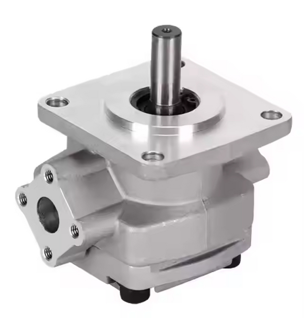
The product family comes after the operating calculation. BLINCE lists several gear-pump ranges, including HGP, AZPW, and SGP configurations. They should be treated as candidate families, not interchangeable boxes.
BLINCE publishes 250 bar as the maximum working pressure on the HGP series page and names forklift steering and machine-tool hydraulic stations as applications. Those entries describe part of the envelope, not a tractor-PTO approval. The order code still has to produce the right displacement, shaft, flange, rotation, speed range, and port arrangement for the duty.
The SGP hydraulic gear pump may be relevant where a compact gear-pump arrangement suits the machine. The AZPW family may be useful where rotation and port configuration are central. For a very large displacement at low shaft speed, a different frame, ratio, or pump type may be more practical than forcing a compact gear pump to meet the calculated flow.
Selection question
Smaller direct-drive gear pump
Larger low-speed gear pump
Higher-speed drive with smaller displacement
Packaging
Usually compact
Larger housing and heavier drive
Adds ratio or PTO-speed requirements
Shaft torque
Lower only if power demand is lower
High at low rpm
Lower torque at higher rpm for same power
Inlet demand
Easier at lower flow
Large volume per revolution
Higher velocity and cavitation sensitivity
Cost and complexity
Often simpler
May require stronger PTO and bracket
Ratio hardware and alignment add work
Best fit
Moderate flow within published limits
Low-speed application with verified torque capacity
When approved pump speed and inlet design allow it
Who should avoid it
Buyers needing flow beyond the frame
Machines with light PTOs or weak supports
Systems without verified speed ratio or adequate suction
The table is a decision aid, not a ranking. A smaller pump is not automatically safer if it runs above its speed or pressure limit. A large pump is not automatically stronger if the PTO cannot carry its torque. A speed-increasing drive is not an upgrade if the inlet and bearings cannot support the higher rpm.
Equipment-Specific Checks
Tractors and Agricultural Implements
A farm implement may spend six months parked, then work a long day around dust, fertilizer, rain, and vibration. Inspect the breather and hose ends before using last season's pump figures. During the actual pass, check whether the tractor holds 540 or 1,000 rpm and whether the implement expects open-center or closed-center supply; both points can change the conclusion.
A sprayer or spreader motor may need steady speed rather than the highest possible flow. If engine rpm changes, a fixed-displacement PTO pump changes delivery with it. A flow control can limit excess speed, but throttling away a large surplus creates heat. Selecting closer to the real operating point is usually more efficient than oversizing the pump and wasting the difference.
Dump Trailers and Tipping Bodies
These applications often have short cycles and high cylinder force. The pump may reach relief pressure near the end of travel if the operator holds the control. Record the required cylinder volume and acceptable raise time before choosing displacement. A 20 gpm pump is unnecessary if the cylinder and structure only need 10 gpm to meet a safe cycle time.
Check lowering flow separately. Gravity-assisted return can exceed pump flow, so the return hose, valve, and tank connection may need to pass more oil than the pump delivers during raising. A larger pump does not solve an undersized lowering path.
Log Splitters, Augers, and Conveyors
A log splitter alternates between rapid movement and high force. An auger or conveyor may run continuously with changing torque. These duties should not share one selection shortcut. The splitter calculation begins with cylinder volume and stroke time; the rotating attachment begins with motor displacement, target rpm, pressure differential, and duty.
When a PTO pump drives a hydraulic motor, compare it with the hydraulic pump and motor matching guide. A motor can be correctly sized and still run slowly if pump flow falls with engine speed or return pressure rises through couplers and valves.
Service Trucks and Mobile Power Units
Service equipment may idle for long periods and then operate a crane, winch, cylinder, or tool circuit. Engine idle speed may not provide the pump rpm assumed in the catalog calculation. If the operator must raise engine speed for useful flow, confirm noise, heat, PTO speed, and vehicle safety controls at that operating point.
Multiple functions require a sequence review. A crane and outrigger may not need full flow simultaneously, while a cooler fan or hydraulic motor may run continuously in the background. Add only flows that truly overlap, but do not ignore priority flow reserved for steering or controls.
Who Should Not Buy a Direct 540 RPM PTO Gear Pump Yet?
Do not order from a flow label alone if the actual pump speed is unknown. A vehicle with an undocumented PTO ratio, slipping clutch, variable engine speed, or extra gearbox cannot be sized responsibly from “540 rpm” written in an email.
The direct-drive purchase should stop when the PTO's continuous torque rating falls below the demand. Our example lands near 334 lb-ft at 540 rpm and 2,500 psi before extra uncertainty is added. The fact that the pump slides onto the spline does not improve that rating.
A second hold point is the old circuit. When its valve, couplers, suction hose, return, filter, or cooler was selected around 12 gpm, ordering 20 gpm first merely moves the argument downstream. The attachment may move; it may also run hotter and become difficult to meter.
Fixed displacement is also a poor starting point for some control requirements. If actuator speed must remain steady while engine rpm varies, or the machine spends long periods at standby and needs load-sensing behavior, the surrounding circuit has to provide that control. Otherwise a variable pump or another architecture belongs in the discussion.
Common Buying and Installation Mistakes
Mistake 1: Treating 540 RPM as the Pump Speed
The PTO may have a ratio, and the engine may not hold its nominal speed under load. Confirm speed at the pump shaft, including any gearbox or belt ratio.
Mistake 2: Choosing From GPM Without Calculating Displacement
The same 20 gpm target works out to roughly 156 cm³/rev at 540 rpm but 84 cm³/rev at 1,000 rpm under the stated efficiency assumption. That difference also appears at the shaft: lower speed means more torque for the same power.
Mistake 3: Comparing Maximum Pressure Only
Maximum pressure does not determine flow, torque capacity, thermal duty, shaft load, or acceptable speed. Select from the complete operating envelope.
Mistake 4: Reversing the Pump
Clockwise and counterclockwise need a defined viewing direction. Confirm the PTO output and pump shaft-end convention before the first start.
Mistake 5: Reusing an Undersized Suction Hose
A larger displacement pulls more oil per revolution. A long, small, soft, or internally damaged hose can starve the new pump even when it fits the port.
Mistake 6: Increasing Relief Pressure to Recover Speed
Relief pressure does not create pump flow. If the implement is slow because of insufficient displacement, low rpm, internal leakage, or restriction, raising the setting adds stress and heat.
Mistake 7: Ignoring PTO and Coupling Torque
The shaft can fit while the torque rating does not. Check continuous and intermittent capacities for the exact PTO, coupling, adapter, and pump shaft.
Mistake 8: Testing Only at No Load
A pump may turn quietly with an unloaded valve and fail when pressure reaches 2,500 psi. Repeat the test at normal oil temperature, expected flow, and realistic load.
Mistake 9: Installing a Larger Pump Into Dirty Oil
Debris from the previous pump can remain in the reservoir, hoses, valve, cooler, and filter. The hydraulic contamination control guide is relevant before the replacement enters the same oil path.
Mistake 10: Buying the Pump Before Checking the Implement
A dragging cylinder, worn motor, blocked coupler, wrong valve center, or undersized return can create a pump complaint. Read the complete failure path before making the pump the first purchase.
A Quote Request That Helps
“Quote a 20 gpm 540 rpm PTO pump” leaves the most important choices unresolved.
A useful request is closer to this:
Tractor-mounted conveyor. PTO tag says 540 rpm; the attached drawing shows clockwise rotation viewed from the output end. Please verify that view against the pump. The motor needs about 20 gpm at the valve. We recorded 2,100 psi in normal material and 2,500 psi briefly when the belt loaded up. Typical cycle is 12 minutes running, 3 minutes stopped, for as long as four hours. Suction hose: 1-1/4 inch ID, 1.2 m, two elbows. ISO VG 46 oil reached 72°C. Photos include the spline, mounting face, tank outlet, ports, coupling, and old nameplate.
That information allows a supplier to challenge the initial assumption. The correct answer may be a specific gear-pump displacement, a different PTO ratio, a stronger coupling, a larger inlet line, a flow target change, or a different pump architecture.
required flow, working pressure, peak pressure, and duty cycle;
existing pump model, displacement, rotation, shaft, flange, and port details;
suction hose ID, length, tank outlet, strainers, valves, and oil viscosity;
pressure-line, valve, coupler, filter, cooler, and return-line sizes;
reservoir volume, oil temperature, ambient temperature, and contamination history;
photos and a short video of the symptom under load where safe.
FAQ
How do I size a PTO hydraulic pump?
Write down the actuator's real flow and loaded pressure, then find the speed at the pump shaft. Use those numbers to screen displacement, power, and torque. Only after that calculation should the exact PTO and pump limits be checked: speed, rotation, mounting, inlet condition, duty, oil temperature, and pressure.
What displacement is needed for a 20 gpm pump at 540 rpm?
Using 90 percent volumetric efficiency for a first pass gives 9.51 in⊃3;/rev, about 156 cm³/rev. That is a size-range warning rather than a model choice. It may lead to a larger frame, a revised flow target, or an approved higher pump speed once PTO torque is known.
How much horsepower does 20 gpm at 2,500 psi require?
The oil receives about 29.2 hp in theory. With 85 percent overall efficiency used for screening, the drive side rises to about 34.3 hp. A cold start or a pressure spike can ask for more, so the final margin comes from the PTO and pump data rather than this single point.
How much PTO torque is needed for 20 gpm at 2,500 psi and 540 rpm?
At 540 rpm, the 34.3 hp input works out near 334 lb-ft. The same power at 1,000 rpm is about 180 lb-ft. These figures are useful because they can disqualify a light PTO early; the maker's continuous and intermittent ratings make the final call.
Is a 1,000 rpm PTO pump better than a 540 rpm PTO pump?
It depends on what is already limiting the installation. At 1,000 rpm the pump can be smaller and shaft torque is lower, but the inlet has less time to fill each revolution and the speed rating matters. Direct 540 rpm is mechanically simpler; its drawback is the large displacement and torque needed for high flow.
Can I use a hydraulic gear pump directly on a tractor PTO?
Sometimes, but connection is only the first check. The rotation and ports must agree, the PTO must carry the torque, and the pump needs suitable speed, pressure, inlet, support, and guarding. An adapter, gearbox, coupling, or external bearing support may be part of the correct installation.
Does increasing the relief-valve setting increase pump flow?
No. A fixed-displacement pump’s theoretical flow mainly follows displacement and speed. A higher relief setting may allow more load pressure, but it does not correct low rpm, worn pump leakage, inlet starvation, or downstream restriction and can add heat or mechanical stress.
Why does a PTO hydraulic pump get hot?
Heat often shows up where excess power is being lost: oil crossing relief, 20 gpm being squeezed through a small valve, a tight coupler, or high return pressure. Starved inlet flow and aeration add their own heat and noise. Record oil temperature and pressure drop at the loaded condition before choosing another cooler.
Can the same PTO pump run both a cylinder and a hydraulic motor?
Possibly, but the valve arrangement, flow priority, pressure needs, return paths, motor case drain, cylinder volume, and simultaneous operation must be checked. A cylinder may need short high-pressure flow, while a motor may need continuous stable flow and low return pressure.
What pump rotation should I order?
Match the pump’s required rotation to the PTO output using the viewing convention specified by both manufacturers. Submit photos and drawings that show the shaft-end view, port positions, and rotation arrows. Do not rely on “clockwise” without a reference direction.
Is a larger PTO pump always faster?
Its theoretical delivery is higher at the same speed. The attachment gains speed only when the PTO can turn it under pressure and the entire oil path accepts the added flow. A restrictive valve or return can leave the operator with more heat instead of more work.
What information should I send for a PTO hydraulic pump quote?
A useful package includes the PTO tag and drawing, ratio, rotation view, torque ratings, measured pump rpm, implement function, loaded pressure, target flow, and run/rest cycle. Add the old pump code, shaft and flange measurements, port and hose photos, suction and return details, reservoir size, oil grade, temperature, and the original complaint.
Final Takeaway
A PTO hydraulic pump is not selected by one speed label, one flow target, or one spline. The useful question is whether the PTO, pump, inlet, control circuit, actuator, return path, reservoir, and cooling system can deliver the required work as one installation.
The calculation leaves one useful warning. With 90 percent volumetric efficiency used for screening, 20 gpm needs about 156 cm³/rev at 540 rpm and 84 cm³/rev at 1,000 rpm. Add 2,500 psi and an 85 percent overall-efficiency assumption: input rises to about 34.3 hp, or 334 lb-ft at 540 rpm. Those figures are not a promised operating point. They are enough to catch an implausible pump-and-PTO combination before money is spent.
For BLINCE to review the pump, send the PTO drawing and rating, measured pump speed, rotation view, loaded flow and pressure, run/rest cycle, shaft and flange measurements, line sizes, reservoir details, oil temperature, and clear installation photos. The useful outcome may be a gear-pump order. It may instead be a ratio change, a larger suction line, or a request for one missing measurement before any model is quoted.
This article is a general engineering guide. Final component selection should be based on machine drawings, measured hydraulic data, working conditions, safety requirements, and confirmation from a qualified hydraulic engineer or supplier.
Blince Hydraulic Team
Blince Hydraulic is an industry-leading company dedicated to precision-engineered fluid power manufacturing and custom hydraulic solutions. Backed by decades of deep field expertise in industrial machinery and thousands of successful global deployments, our engineering team focuses entirely on high-performance hydraulic component manufacturing, including specialized orbital motors, high-pressure travel drives motor, and robust directional control valves. Our production infrastructure utilizes state-of-the-art multi-axis CNC machining systems and is fully ISO 9001 certified to guarantee repeatable volumetric accuracy across every single manufacturing run.
We deliver fast, highly dependable, and cost-efficient hydraulic solutions to heavy industry distributors, machinery OEMs, and maintenance crews across more than 150 countries. Whether your active project calls for a small-volume batch of customized shaft profiles or a large-scale production run of severe-duty cast iron gear pump, we configure our flexible production schedules to meet your target lead times with total pricing predictability. Partnering with Blince means securing maximum system efficiency, elite material quality, and uncompromised fluid power professionalism.
To learn more about our complete product lineup, visit our official website: www.blince.com.