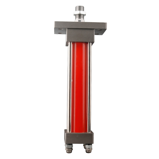
A long hydraulic cylinder can lift the load in the workshop and still be the wrong cylinder for the machine.
The usual warning is not dramatic at first. The rod looks straight when retracted. The pressure gauge reaches the expected number. During a slow no-load extension, everything appears normal. Then the cylinder is installed at full reach, the load shifts slightly, and the rod begins to bow. A seal starts leaking a week later. The gland wears on one side. In a worse case, the rod bends permanently or the cylinder folds sideways before the relief valve opens.
The buying conversation often starts with bore and pressure: “We need an 80 mm bore cylinder rated for 160 bar.” Those numbers describe potential push force, but they do not prove that the extended rod can carry that force as a compression column. Stroke, exposed rod length, mounting style, rod-end guidance, side load, dynamic shock, and the way the machine frame moves are just as important.
That is the core of hydraulic cylinder buckling. A push-stroke cylinder does two jobs at once: it generates force from pressure, and its piston rod must remain stable while carrying that compressive force. A larger bore can increase the force trying to buckle the rod. A longer stroke can reduce column stability sharply. Copying only the flange, port thread, and nominal pressure can therefore produce a replacement that fits the machine but is not safe for the working geometry.
This article gives a field-oriented method for evaluating rod diameter, effective length, mounting, and push load before ordering a replacement hydraulic cylinder. It includes an Euler screening calculation, explains why the result is only preliminary, compares larger rods with stop tubes and external guides, and shows what information a cylinder supplier needs before making a responsible recommendation.
The Short Answer
Hydraulic cylinder rod buckling occurs when a rod under compression becomes laterally unstable before the material reaches its simple compressive strength limit. The risk rises quickly as the unsupported or effectively unsupported length increases. For an ideal round rod, Euler column theory shows that critical load is proportional to the fourth power of rod diameter and inversely proportional to the square of effective length.
That relationship is useful, but a real cylinder is not an ideal laboratory column. The piston, rod bearing, clevises, spherical bearings, frame stiffness, mounting clearance, stop tube, load guidance, and stroke position all change the boundary condition. Manufacturer sizing charts or an application review should make the final decision. Parker’s application guide, for example, directs users to determine mounting and guidance conditions, establish a basic length, check stop-tube requirements, and then select rod diameter from the load and length data rather than from bore alone .
For purchasing, the practical rule is simple: do not approve a long-stroke push cylinder from bore, stroke, and pressure alone. Add actual push load, maximum extension, mount type, rod-end connection, load guidance, operating angle, speed, shock, and safety consequence.
Why Rod Buckling Is Often Misdiagnosed
A bent rod is visible, so the rod material gets blamed. Yet many buckling failures begin outside the rod. A worn clevis pin allows the load line to move. A base plate twists when the cylinder reaches maximum force. A trunnion is installed a few millimeters off center. A guided carriage binds near the end of travel. The rod is then asked to carry compression and bending at the same time.
The opposite mistake also occurs. A technician sees side load and assumes alignment is the only issue, even though the rod is simply too slender for the push force and effective length. The hydraulic cylinder installation guide is useful for checking pin freedom, mounting faces, and linkage alignment, but installation quality does not remove the need for a buckling calculation.
A third error comes from pressure testing. If an 80 mm bore cylinder is loaded until a gauge shows 160 bar, the gauge confirms pressure at its connection. It does not confirm that the rod is straight, that the load is concentric, or that the mount behaves like the assumption used in the calculation. The pressure-gauge placement guide explains why one local reading cannot describe every loss or mechanical condition in a circuit.
Start With the Motion, Not the Cylinder Label
Before calculating anything, write down what the machine does during the push stroke.
Does the rod push vertically, horizontally, or at a changing angle? Is the cylinder fixed at both ends, or does it pivot on pins? Does an external rail guide the load, or is the rod expected to locate the moving structure? Is maximum force required near the beginning of the stroke, in the middle, or when the rod is almost fully extended? Does the load remain centered, or can wind, material buildup, linkage wear, or an uneven payload move it sideways?
These questions change the effective column length. A rigidly guided rod end behaves differently from a free or poorly guided end. A fixed mount on a stiff test frame may not behave like the same mounting pattern welded to a thin machine bracket. On a long-stroke cylinder, the last 100 mm of extension can be the most demanding part of the cycle because the exposed rod is longest while the linkage may also demand its highest force.
A useful service note sounds like this:
The cylinder pushes a 9 kN guided carriage horizontally. Bore is 80 mm, rod is 45 mm, and stroke is 1,200 mm. The rod is about 1,500 mm from the effective head support to the load connection at full extension. Working pressure reaches 160 bar during the final 150 mm. The rear clevis pivots, but the rod-end eye has noticeable side clearance. The previous rod bent toward the operator side.
That description gives a supplier more engineering value than “quote the same 80/45 × 1,200 cylinder.” It identifies force, effective length, guidance, peak position, and the direction of the previous failure.
What Buckling Actually Means
Material yield and column buckling are different failure modes. A short, thick rod may fail only when compressive stress becomes too high. A long, slender rod can lose lateral stability at a much lower average stress. Once it bows, the load becomes eccentric, bending moment increases, and the deflection can grow rapidly.
For an ideal elastic column, Euler’s equation is:
Pcr = π⊃2; × E × I / (K × L)⊃2;
where:
Pcr is the theoretical critical buckling load in newtons;
E is Young’s modulus of the rod material in pascals;
I is the second moment of area in m⁴;
K is the effective-length factor determined by end conditions;
L is the unsupported physical length in meters.
For a solid round rod:
I = π × d⁴ / 64
where d is rod diameter in meters.
The two relationships explain why apparently small changes matter. Increasing rod diameter from 45 mm to 50 mm is an 11.1% diameter increase, but the ideal bending stiffness term rises by roughly 52% because diameter is raised to the fourth power. Doubling effective length, however, reduces the ideal critical load to one quarter.
Do not treat those percentages as a cylinder rating. Threaded rod ends, cross holes, corrosion, chrome damage, manufacturing tolerances, dynamic loading, initial straightness, bearing clearance, and real mount flexibility all reduce the confidence of a simple ideal-column calculation. A wear-resistant cylinder rod product may address surface durability in its intended application, but surface treatment alone does not establish buckling capacity.
A Worked Screening Example
Consider a double-acting cylinder with the following preliminary data:
bore diameter: 80 mm;
rod diameter: 45 mm;
maximum push pressure: 160 bar;
effective physical length used for screening: 1.50 m;
steel elastic modulus assumption: 200 GPa;
load treated first as centered and static;
friction, shock, side load, and safety factor not yet included.
Step 1: Calculate Theoretical Push Force
The full piston area is:
A = π × D⊃2; / 4
A = π × 0.080⊃2; / 4 = 0.0050265 m²
At 160 bar, or 16 MPa:
F = pressure × area
F = 16,000,000 × 0.0050265 = 80,425 N ≈ 80.4 kN
This is theoretical cap-end force before mechanical friction and before considering whether the pump, valve, hoses, or relief setting can maintain that pressure under motion. It is also the compression demand that the rod may experience if the machine actually reaches that pressure while pushing.
Step 2: Calculate the Rod Area Moment
For a 45 mm solid rod:
I = π × 0.045⁴ / 64 ≈ 2.013 × 10⁻⁷ m⁴
Step 3: Compare Different Ideal End Conditions
Using L = 1.50 m:
Idealized end condition
Example K factor
Effective length K × L
Euler critical load
Comparison with 80.4 kN push force
Fixed-fixed
0.5
0.75 m
about 706 kN
High theoretical margin, but rarely a fair assumption for a pin-mounted machine
Fixed-pinned approximation
0.7
1.05 m
about 360 kN
Still depends on genuine frame and rod-end restraint
Pinned-pinned
1.0
1.50 m
about 177 kN
Theoretical ratio is only about 2.2 before real-world reductions
Fixed-free
2.0
3.00 m
about 44 kN
Below the theoretical hydraulic push force
The same 45 mm rod moves from apparently comfortable to clearly inadequate only because the assumed end condition changes. That is why a generic online hydraulic cylinder rod buckling calculator cannot finish the selection unless its effective-length model matches the real machine.
Even the pinned-pinned result should not be approved as “safe” from this table. A theoretical ratio of about 2.2 may be consumed by shock, imperfect alignment, weak mounting, initial rod straightness, thread details, and the supplier’s required design margin. Final selection belongs in the cylinder manufacturer’s load-length chart or a documented engineering review.
Step 4: See What a Larger Rod Changes
Keeping the same 1.50 m length and pinned-pinned idealization, the Euler values are approximately:
Rod diameter
Ideal pinned-pinned critical load
Change from 45 mm
Important purchasing consequence
45 mm
177 kN
baseline
May be too close after real conditions and safety factors are applied
50 mm
269 kN
+52%
Higher stability, but lower annular area and higher retract flow for the same pump input
56 mm
424 kN
+140%
More stiffness and cost; rod-end and gland dimensions also change
63 mm
678 kN
+284%
Stronger column, but not a cure for side load or weak machine guidance
This comparison shows the benefit of a larger rod, but it also exposes a common sales shortcut. “Use the biggest rod available” is not a complete answer. The rod must fit the cylinder series, pressure envelope, seal system, mount, retract-force requirement, desired speed, and machine space. A heavy-duty tie-rod cylinder may offer a more suitable construction for a demanding application than a compact cylinder, but the exact series data still need to be checked against the load and effective length.
Bore Size Can Make the Buckling Problem Worse
Buyers sometimes increase bore because the old cylinder feels weak. At the same pressure, a larger bore creates more push force. If rod diameter and effective length remain unchanged, that extra force may move the design closer to buckling.
At 160 bar, theoretical push force is about 50.3 kN for a 63 mm bore, 80.4 kN for an 80 mm bore, and 125.7 kN for a 100 mm bore. Moving from 80 mm to 100 mm raises theoretical force by roughly 56%, but it does nothing by itself to increase the column capacity of a 45 mm rod.
A larger bore also needs more oil for the same speed. If pump flow stays fixed, extension becomes slower. If the pump is increased to restore speed, the valve, hose, fittings, filter, and return path must carry the added flow. This is why cylinder bore selection should be tied to force, speed, and rod stability rather than treated as a one-number upgrade.
Push Stroke and Pull Stroke Are Not the Same Buckling Case
The rod is mainly in tension during a pull stroke. Tension does not produce Euler buckling, although rod threads, attachment strength, fatigue, and side load still matter. During a push stroke, the rod carries compression and can become unstable.
This distinction matters on reversing machines. A cylinder may pull a scraper smoothly for years but bend after the linkage is modified so the same cylinder pushes the load. The bore, rod, ports, and pressure are unchanged; the structural job is not.
If a replacement is ordered for a double-acting machine, state which direction carries the highest load. The supplier should not assume that the cap-end stroke is the critical one simply because it creates more theoretical force. Geometry can make the rod-end stroke mechanically harder, while a counterbalance or pressure-control arrangement may also change actual cylinder pressure. When holding and motion interact, the cylinder drift troubleshooting guide helps separate structural movement from hydraulic leakage.
Effective Length Depends on Mounting and Guidance
The visible rod length is not always the effective buckling length. A clevis-mounted cylinder that pivots at both ends behaves differently from a flange-mounted cylinder with a rigidly guided rod-end carriage. A spherical bearing may prevent binding but also allows angular movement. A nominally guided slide may lose restraint when its wear pads develop clearance.
Parker’s published engineering data groups applications by mount and rod guidance, then uses a basic or adjusted length for rod and stop-tube selection. Its guidance also warns that piston rods are not normally intended to absorb bending moments or loads perpendicular to rod travel.
Field evidence should agree with the assumed mount. With the machine depressurized and safely supported, inspect pin clearance, spherical bearings, bushings, welds, frame plates, external guides, and attachment play. Watch the rod through the full stroke from two directions. A polished stripe on one side, uneven gland wear, a bent clevis, or repeat seal leakage is evidence that the load line is moving.
The HSG hydraulic cylinder, a compact CX cylinder, and a tie-rod design do not share one universal mounting model. Series choice should follow the machine structure and service access, not only the pressure label.
Side Load Is Not Solved by a Larger Rod
A larger rod increases stiffness. That can delay visible bending, but it may also transmit more side force into the rod bearing, gland, piston, and mounting structure. If the load needs lateral guidance, provide an external guide or correct the linkage.
The tradeoff is important:
Option
Main advantage
Main limitation
Best use
Larger rod diameter
Raises column stiffness and theoretical buckling load
Adds cost and mass; changes annular area; cannot correct misalignment
Verified compressive-load stability issue with acceptable circuit effects
Stop tube
Increases distance between piston and rod bearing at full extension, reducing bearing load
Increases gross cylinder length and may affect package space
Long push strokes where manufacturer data calls for it
External linear guide
Carries transverse load and controls motion path
Adds components, alignment work, lubrication, and space
Carriages, platens, gates, and tooling with unavoidable side forces
Larger bore
Increases push force at the same pressure
Can increase buckling demand and oil consumption
A genuine force shortage after rod stability and circuit capacity are checked
Higher relief setting
May allow higher cylinder force
Adds stress and heat; does not improve rod stability
Only when the whole system is rated and the required force is documented
Parker describes a stop tube as a way to increase the distance between the piston bearing and rod bearing, reducing bearing load on long push-stroke cylinders near full extension (Parker heavy-duty cylinder engineering data). It does not turn the rod into a linear rail, and it does not replace a rod-diameter check.
Rod-End Threads and Attachments Matter
The rod body may pass a preliminary buckling screen while the rod-end connection remains the weak point. A reduced threaded section has less area and different stress concentration. A long rod extension increases effective length. A clevis with an offset pin introduces bending. A jam nut that is not seated can allow movement and fretting.
Do not model the cylinder as a uniform 50 mm bar if the load actually enters through a smaller threaded section or a long custom extension. Send the rod-end drawing with thread size, engagement length, shoulder position, clevis dimensions, pin diameter, and any spacer or spherical bearing.
If the previous failure occurred at the thread runout rather than as a smooth mid-span bow, the investigation should include fatigue, thread geometry, loose attachments, and shock. A buckling calculator may be looking at the wrong failure mode.
Dynamic Loads Are Higher Than the Quiet Calculation
The 80.4 kN example assumed static pressure and centered load. Real machines stop, reverse, strike material, and reach mechanical limits. A dump body can shift as material slides. A clamp can hit a hard part. An excavator attachment can catch in the ground. These events create transient loads that are not visible in a steady-state spreadsheet.
A relief valve limits hydraulic pressure only after pressure reaches its setting and the valve responds. Mechanical inertia and frame impact still matter. If the cylinder is driven rapidly toward a hard stop, reducing speed near the endpoint or using appropriate cushioning can protect the machine, but cushioning does not make an undersized rod safe through the full stroke.
For high-consequence lifts, presses, tilting systems, or suspended loads, ask for a documented load case rather than applying a casual multiplier. Include maximum normal load, credible overload, acceleration, deceleration, impact, wind or off-center load, and the result of a hose or valve failure. Safety-related load holding also needs the correct valve and mechanical design; a large rod is not a load-holding device.
Stop Tube, Long Stroke, and Closed Length
Long-stroke buyers often focus on net travel and forget gross cylinder length. A stop tube occupies internal length, so the cylinder package may need to become longer to preserve the required net stroke. That can interfere with the machine frame, transport envelope, or service access.
The decision should therefore be made before the drawing is frozen. A compact hydraulic cylinder can solve a space problem in the right duty, but compact packaging does not automatically suit a long unsupported push stroke. Conversely, a longer heavy-duty cylinder may need frame changes that the buyer did not include in the first quote request.
Compare three dimensions on the drawing: retracted pin-to-pin length, extended pin-to-pin length, and the effective unsupported or basic length used for the stability check. They are related, but they are not interchangeable.
Temperature, Contamination, and Wear Change the Real Margin
Buckling is mechanical, yet the hydraulic condition can move the operating point. Cold oil may cause pressure spikes and slow motion. Hot oil can increase internal leakage, so the pump runs longer or the operator holds the valve against relief. Contamination can score the rod, damage bearings, or make a valve shift unpredictably.
A rod with corrosion pits or chrome flaking should not be treated as the perfect round section used in a clean calculation. Nor should a worn gland be assumed to guide the rod as designed. If the machine has already suffered a pump or component failure, the hydraulic contamination control guide is relevant before a new cylinder is installed into the same oil path.
Hose routing also affects side load. A short, stiff hose can pull on a port or cylinder as the machine moves. A hose that rubs, twists, or reaches its minimum bend radius at full extension can apply an unexpected transverse force. Check the hydraulic tubing and hose selection guide when the rod bends only near one end of travel or after hose replacement.
Equipment-Specific Checks
Dump Trailers and Tipping Bodies
A tipping cylinder works through changing geometry. The highest cylinder force may occur early in the lift when leverage is poor, while the longest exposed rod occurs later. Material can stick to one side of the body and move the load line away from the cylinder axis.
Record body weight, payload, hinge location, cylinder pin coordinates, initial angle, maximum angle, and whether the load can remain uneven. A larger bore may start the body more easily, but it can also increase compressive demand on the rod and mounting brackets. Buyers who only know payload tonnage do not yet have enough information for a buckling review.
Presses and Clamping Machines
Press and clamp cylinders may have good external guidance, which can reduce lateral movement, but tooling alignment and platen stiffness still matter. A load cell or pressure reading should be recorded near the point of maximum extension, not only at the beginning of the cycle.
A heavy-duty cylinder series may be appropriate where serviceability and structural duty justify it. A buyer should still state whether the cylinder pushes against a rigid die, a spring-like assembly, or a part that can shift during compression.
Agricultural and Forestry Equipment
Pins wear, frames flex, and loads rarely stay cleanly centered in field equipment. Mud can hide a bent bracket. A log, bale, or implement can pull the linkage sideways. Seasonal storage can leave corrosion on an exposed rod.
Check the machine under the real attachment and at the real operating angle. A cylinder that passes on a workshop stand may see a different effective length on a loader, harvester, splitter, or forestry grapple. For these machines, rod protection and seal life matter, but a durable rod surface still needs correct structural alignment.
Mobile Construction Machinery
Boom, blade, stabilizer, and attachment cylinders can experience shock and rapidly changing load direction. A worn pin or oval hole changes the boundary condition every time the load reverses. If a rod bends repeatedly in the same direction, mark the machine orientation and inspect the whole linkage before ordering another cylinder.
Do not assume that a cylinder bursting article and a buckling article describe the same failure. Cylinder bursting concerns pressure containment failures; rod buckling concerns compression stability. The same event can damage both, but the calculations and evidence are different.
Who Should Not Buy a Larger-Bore Replacement
Do not buy a larger-bore cylinder as the first response if the original rod bent, the linkage is misaligned, the carriage binds, the mount flexes, or the effective push length has increased. More bore area raises force and can make the structural problem worse.
Do not choose a long-stroke cylinder from an online calculator alone when the load is suspended, people work near the mechanism, a failure can overturn equipment, or the mounting condition is uncertain. These applications need a documented manufacturer or engineering review.
Do not buy the stiffest or largest rod merely because it fits the bore series if the machine requires high retract force, limited return flow, low moving mass, or a short retracted package. The larger rod changes annular area and can change circuit behavior.
Finally, do not buy another identical cylinder after two similar rod failures until the pin centers, frame alignment, guidance, hose forces, pressure history, and failure direction have been recorded. Repetition is evidence that the original cause remains.
Common Buying and Diagnostic Mistakes
Mistake 1: Calculating Push Force but Not Column Stability
Bore and pressure answer “how hard can the piston push?” They do not answer “will the extended rod remain straight?” Both calculations belong in a long push-stroke selection.
Mistake 2: Using Stroke as the Only Length
Net stroke is not always the effective buckling length. Rod extension, mount position, clevis geometry, stop tube, and external guidance alter the basic length used by manufacturer methods.
Mistake 3: Assuming Pinned and Fixed Ends Are Interchangeable
The worked example changed from 177 kN to 44 kN when the ideal K factor changed from 1 to 2. An optimistic end condition can produce a dangerously optimistic result.
Mistake 4: Increasing Bore Without Increasing Rod Capacity
At the same pressure, more bore area means more compression force. A force upgrade may require a rod, mount, pin, frame, and oil-flow review.
Mistake 5: Using a Larger Rod to Hide Side Load
Stiffness is not guidance. Correct the load path or add an appropriate external guide instead of asking the rod bearing to carry a bending problem.
Mistake 6: Ignoring the Rod-End Thread
The smallest and most highly stressed section may be at the thread or cross hole. Include custom rod extensions and attachments in the review.
Mistake 7: Testing Only Retracted or at No Load
The risk is often highest close to full extension under push load. A quiet bench cycle does not reproduce that condition.
Mistake 8: Treating Stop Tube as a Universal Cure
A stop tube can reduce bearing stress at full extension. It does not repair flexible mounts, remove side load, or automatically make the rod diameter adequate.
Mistake 9: Copying the Old Cylinder After the Machine Changed
A heavier attachment, different pin location, altered stroke, higher relief setting, or faster cycle can invalidate the old selection even when the old part number is known.
What to Send for a Useful Cylinder Quote
“Quote 80/45 × 1,200 at 160 bar” is not enough for a long push-stroke cylinder. Send a short application package:
cylinder bore and rod diameter, if already constrained;
net stroke, retracted length, and any nonstandard rod extension;
maximum normal working pressure and relief setting;
actual required push and pull loads, including load direction;
cylinder speed and cycle frequency;
mounting type at cap end and rod end;
whether pins pivot freely and whether spherical bearings are used;
external guidance method and distance from the load connection;
maximum physical and effective length at the critical stroke position;
horizontal, vertical, or variable installation angle;
dynamic events such as impact, rapid reversal, material shift, or emergency stop;
rod-end thread, clevis, pin, cross hole, or custom attachment drawing;
oil type, temperature range, contamination history, and environment;
photos of the whole mechanism at retracted, mid-stroke, and full extension;
photos and measurements of the failed rod, gland, pins, and mounting brackets.
For an existing machine, include the failure story. “Rod bent 12 mm toward the left side after the body reached 70% lift” is useful. “Cylinder bad” is not.
BLINCE can compare that information with its hydraulic cylinder range, including tie-rod, compact, HSG, MOB, and application-specific rod options. The outcome may be a larger rod, a different cylinder series, a stop-tube requirement, a mounting correction, an external guide, or a request for more machine data. A technically honest quote may challenge the cylinder requested on the first email.
FAQ
What is hydraulic cylinder rod buckling?
It is lateral instability of a piston rod under compressive push load. A long or slender rod can bow before its simple compressive stress reaches material yield. Stroke, effective length, rod diameter, end restraint, guidance, side load, and dynamic force all influence the risk.
How is hydraulic cylinder buckling load calculated?
Euler’s ideal-column equation, Pcr = π⊃2;EI/(KL)⊃2;, is useful for preliminary screening. For a round rod, I = πd⁴/64. Final selection should follow the cylinder manufacturer’s load-length chart or engineering method because real mounts, rod ends, bearings, stop tubes, clearances, and safety margins are not captured by a generic calculation.
Is the cylinder stroke the same as the effective buckling length?
Not necessarily. Effective or basic length can include rod extension and mounting geometry, and it changes with end guidance. Manufacturer charts define how to establish the length for each mounting group. Use the fully extended critical geometry, not only the catalog stroke.
Does a larger rod always prevent buckling?
It raises theoretical column stiffness strongly, but it does not correct side load, flexible brackets, binding guides, worn pins, or shock. It also reduces annular area, affects retract force and return flow, adds mass, and may require a different gland or cylinder series.
Does a larger bore make a cylinder safer?
Not automatically. A larger bore creates more push force at the same pressure and can increase buckling demand if rod diameter and effective length are unchanged. It also needs more oil for the same speed.
Can a stop tube replace a larger piston rod?
No. A stop tube can increase bearing separation and reduce bearing load near full extension. Rod diameter still needs to be checked for compression stability, and the machine may need external guidance.
Why did the new cylinder rod bend when the old one lasted for years?
Possible causes include a changed rod diameter or extension, different mount clearance, worn pins, altered linkage geometry, a higher relief setting, a new attachment, faster operation, poor alignment, or loss of external guidance. Compare the complete old and new installation rather than the part labels alone.
Can a hydraulic cylinder rod buckle below the relief-valve setting?
Yes. Buckling depends on compressive force and effective geometry. A long slender rod or poorly restrained mount may become unstable at a load below the hydraulic system’s maximum pressure rating.
Should a buckling check use working pressure or relief pressure?
Use credible maximum force for the load case, including system settings and transient conditions, under the responsible engineering method. Normal working pressure alone may miss an overload or end-of-stroke event; blindly using only relief pressure may also misrepresent the actual machine sequence. Document both.
What should I inspect after a rod bends?
Record bend direction and stroke position, then inspect pins, clevises, spherical bearings, rod-end threads, gland wear, external guides, frame welds, hose forces, pressure history, and load distribution. Do not straighten or discard the evidence before the cause is reviewed.
Who should not use a generic hydraulic cylinder buckling calculator as the final answer?
Anyone selecting a cylinder for lifting people, suspended loads, high-speed presses, overturning-risk machinery, uncertain mounting, severe shock, or poorly guided long strokes should obtain a documented application review. A calculator is a screen, not a safety certification.
Final Takeaway
A hydraulic cylinder can match bore, stroke, pressure, ports, and pin centers and still have the wrong rod for the job. The missing question is usually structural: what compression load reaches the rod when it is longest, and how is that rod actually restrained?
Use force calculation to establish the demand. Use effective length and rod diameter to screen column stability. Then bring the machine back into the decision: mounting stiffness, pin clearance, external guidance, side load, shock, rod-end geometry, temperature, and service history. A larger rod, stop tube, external guide, or different cylinder series may help, but each solves a different problem.
For a hydraulic cylinder rod buckling review, send BLINCE the bore, rod, stroke, working and relief pressure, mounting drawings, rod-end details, pin-to-pin dimensions, maximum extension, load and speed, installation angle, guidance method, and photos of the mechanism and any previous failure. BLINCE can use that evidence to review the requested hydraulic cylinder and identify which dimensions still need confirmation before quotation.
This article is a general engineering guide. Final component selection should be based on machine drawings, measured hydraulic data, working conditions, safety requirements, and confirmation from a qualified hydraulic engineer or supplier.
Blince Hydraulic Team
Blince Hydraulic is an industry-leading company dedicated to precision-engineered fluid power manufacturing and custom hydraulic solutions. Backed by decades of deep field expertise in industrial machinery and thousands of successful global deployments, our engineering team focuses entirely on high-performance hydraulic component manufacturing, including specialized orbital motors, high-pressure travel drives motor, and robust directional control valves. Our production infrastructure utilizes state-of-the-art multi-axis CNC machining systems and is fully ISO 9001 certified to guarantee repeatable volumetric accuracy across every single manufacturing run.
We deliver fast, highly dependable, and cost-efficient hydraulic solutions to heavy industry distributors, machinery OEMs, and maintenance crews across more than 150 countries. Whether your active project calls for a small-volume batch of customized shaft profiles or a large-scale production run of severe-duty cast iron gear pump, we configure our flexible production schedules to meet your target lead times with total pricing predictability. Partnering with Blince means securing maximum system efficiency, elite material quality, and uncompromised fluid power professionalism.
To learn more about our complete product lineup, visit our official website: www.blince.com.