A machine specification asks for fast approach, a slow loaded stroke and a short pressure hold. The purchasing sheet contains two large numbers: maximum flow and maximum pressure. Multiplying them looks like a sensible way to choose the drive. But those demands may occur at different times—or the circuit may make them occur together at the pump even when they do not occur together at the cylinder.
Short answer
For a hydraulic pump selection calculation, divide the cycle into operating stages, calculate each stage's actuator demand, then determine the flow and pressure the pump must actually supply. Select displacement from required delivery at available shaft speed, and check drive power at simultaneous pressure–flow points. A smaller drive is justified only when the control circuit limits the pump's real demand, including transitions and credible abnormal states.
Start with a cycle record, not two maximum values
A useful sizing sheet describes what happens between the beginning of one cycle and the beginning of the next. Record approach, loaded travel, dwell, return and waiting time separately. Identify which actuators operate together and which movements are prevented by the control sequence. Then attach the relevant pump-outlet pressure to each state rather than copying the relief setting into every row. The flow calculation guide supports the volume calculation, while pressure test-point placement helps distinguish a local actuator reading from the pressure the pump must overcome. Neither a cylinder speed target nor a pressure rating is a complete operating point.
For an existing machine, distinguish a new production target from lost performance. A cylinder that once met the timing requirement but now slows after warming up needs diagnosis before a larger pump. Record oil temperature, shaft speed and loaded delivery under comparable conditions; otherwise the replacement specification may compensate for leakage or a restriction that remains in the system. The oil viscosity discussion explains why temperature belongs beside the measurements, and the contamination-control guide provides the accompanying fluid-condition checks. On a new design, mark missing values as estimates rather than presenting them as measurements.
Published selection methods also use time-dependent demand. Bosch Rexroth's Size & Select Assistant accepts pressure, flow and duration by cycle phase and treats dynamic behavior and component utilization separately. That supports a staged calculation, not a promise that a low average load permits any smaller motor. This article applies that principle to an illustrative cylinder cycle. It does not select a Rexroth or BLINCE model through the tool, establish press safety compliance, or replace the machine builder's assessment of starting, transitions, stopping and failure behavior.
What the product pages establish—and what they leave open
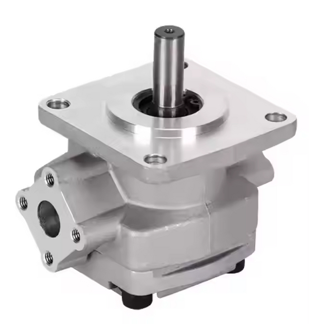
BLINCE lists hydraulic gear pumps and a PVE variable-displacement axial piston pump family. The circuit requirement determines which route to investigate; matching a maximum-flow figure does not make the two architectures interchangeable. The current public pages establish product-family listings, but this example does not transfer a series-level pressure, speed or efficiency claim into a specific order. Obtain the complete configuration and its approved operating envelope before comparing a candidate with the duty sheet. An illustrated displacement below is a calculation input, not a claim that a particular stocked pump meets every condition.
The 20VQ, 25VQ, 35VQ and 45VQ product page offers another pump-family reference with displacement codes and differing published limits. A family heading cannot establish one continuous pressure or speed limit for every displacement. For the drive side, the electric pump selection guide separates hydraulic demand from motor and supply considerations. Bring those two documents together only after identifying the exact pump code, control type, fluid, mounting and operating speed. A larger numerical rating does not settle whether the candidate can deliver the required sequence, and an acceptable steady-state point does not prove acceptable transient behavior.
Worked example: one cylinder, three different flow demands
Consider a hypothetical horizontal, double-acting, single-rod cylinder in a conventional open circuit. It has a 100 mm bore, a 60 mm rod and a 500 mm stroke. There is no regeneration circuit, accumulator assistance or second moving actuator. The illustrative sequence is 400 mm approach in four seconds, the remaining 100 mm working stroke in ten seconds, six seconds of hold, a full return in five seconds and fifteen seconds waiting. These assumptions keep the geometry visible. Use the pump-flow method for a different actuator, and check tandem supply arrangements before applying the example to several independently supplied functions.
The movement times here describe constant-speed portions for a preliminary calculation; acceleration, deceleration, compression and valve response are omitted. They are not free time. If four seconds is the entire available approach window, its moving portion may be shorter and its peak flow higher. The electric-drive duty discussion is relevant when the drive must accelerate repeatedly, while coupling and shaft checks become important when those demands reach the pump mechanically. Keep the first calculation and the later dynamic allowance separate so that the reviewer can see what has been estimated and what still needs confirmation.
Calculate chamber areas and delivered volume
For bore D, rod diameter d and movement length L, use millimetres throughout the area and volume calculation:
Cap-end area Ac = π × D⊃2; / 4
 = π × 100⊃2; / 4
 = 7,853.98 mm²
Annular area Aa = π × (D⊃2; − d⊃2;) / 4
 = π × (100⊃2; − 60⊃2;) / 4
 = 5,026.55 mm²
Chamber volume V [L] = A [mm²] × L [mm] / 1,000,000
Required chamber flow Q [L/min] = 60 × V [L] / t [s]
Approach: V = 7,853.98 × 400 / 1,000,000 = 3.1416 L
 Q = 60 × 3.1416 / 4 = 47.12 L/min
Working stroke: V = 7,853.98 × 100 / 1,000,000 = 0.7854 L
 Q = 60 × 0.7854 / 10 = 4.71 L/min
Retraction supply: V = 5,026.55 × 500 / 1,000,000 = 2.5133 L
 Q = 60 × 2.5133 / 5 = 30.16 L/min
The pump must support about ten times as much useful cylinder flow during approach as during the working stroke. Choosing only the working requirement would make approach too slow; selecting only the approach requirement leaves the control design unfinished. At each stage, the cylinder either receives the intended flow or moves at a different speed. The remaining pump delivery must be reduced, routed elsewhere or dissipated through a pressure drop. The flow-sizing explanation establishes the demand side; pressure measurements along the delivery path help establish where the proposed circuit spends that flow under load.
During retraction, the cap-end chamber empties while the smaller annular chamber fills. Volume continuity therefore gives a return flow different from pump supply. This matters before the filter, cooler and return plumbing are selected, particularly if another branch joins that line. Use the return-path considerations for coolers together with the reservoir return arrangement to follow the oil beyond the cylinder. Do not copy 30.16 L/min into every component's sizing box. The area-ratio result below assumes the stated non-regenerative circuit and negligible leakage, not every possible cylinder connection.
Retraction return flow = supply flow × Ac / Aa
 = 30.16 × (7,853.98 / 5,026.55)
 ≈ 47.12 L/min
Convert the highest delivery requirement into displacement
For preliminary sizing at a fixed shaft speed, estimated pump delivery is Q = Vg × n × ηv / 1000, with displacement Vg in cm³/rev, speed n in rpm and volumetric efficiency ηv as a decimal. Assume 1,450 rpm and ηv = 0.90 solely for this example. The pump-flow calculation page explains these variables; the gear-pump category is a starting point for requesting actual displacement choices and performance curves. Efficiency changes with the operating point. A single assumed value is useful for a first calculation but is not a guarantee at cold start, hot oil, low speed and maximum pressure alike.
The 40 cm³/rev example supplies more than the calculated approach requirement under the assumed conditions. That difference is not a universal recommended margin and is not an instruction to buy a 40 cm³ pump. Check whether the candidate delivers enough at the worst relevant temperature and load, then decide how excess delivery is managed during slower movements. A VQ displacement-code comparison shows why the exact size must be identified, while pump coupling verification reminds the purchaser that a numerical flow match does not establish shaft, flange or installation compatibility. Add allowances by their cause rather than hiding them in an unexplained percentage.
Power depends on what happens at the pump
Use simultaneous pump pressure difference and actual pump outlet flow when estimating hydraulic output power. Mechanical shaft input is higher because the pump has losses; electric supply input includes additional motor and drive losses. These boundaries matter when comparing quotations. Parker's hydraulic pump equations, printed page 17 give the pressure–flow power relationship with an efficiency correction. In SI units, one bar is 100,000 Pa and one litre per minute is 1/60,000 m³/s, producing the divisor 600 for power in kW.
Suppose the illustrative pump pressure differences are 40 bar during approach, 180 bar during the working stroke and 50 bar during retraction. These are assumed pump operating pressures, not force calculations or recommended settings. If the pump could match just the required movement delivery, the following steady-state powers would result with an assumed total efficiency of 0.85. The pressure-measurement guide helps establish comparable field inputs, and the AC/DC sizing discussion explains why the shaft figures remain different from electrical input. Hold leakage, waiting losses and transient demands are deliberately not assigned invented values.
Movement
Assumed pump Δp
Required delivery
Calculated hydraulic power
Estimated shaft input, ηt = 0.85
Approach
40 bar
47.12 L/min
3.14 kW
3.70 kW
Working stroke
180 bar
4.71 L/min
1.41 kW
1.66 kW
Retraction
50 bar
30.16 L/min
2.51 kW
2.96 kW
Multiplying 180 bar by 47.12 L/min describes a different operating point: approximately 14.14 kW hydraulic output and 16.63 kW shaft input at the assumed efficiency. It does not describe any one movement in the demand-matched table. That observation identifies a control opportunity, not an approved smaller motor. The PVE variable-displacement route requires an appropriate control configuration to change delivery, and the tandem-circuit guide shows why separate pump sections need their own pressure and flow accounting. Before removing the higher power point from the drive specification, establish what prevents it from occurring.
A fixed-displacement pump delivering 52.20 L/min can still see 180 bar while the cylinder uses only 4.71 L/min. In a hypothetical throttled working stage where the surplus crosses a relief path at that pressure, the pump supplies the full flow against the high pressure. The shaft estimate is then 180 × 52.20 / (600 × 0.85) = 18.42 kW. The gear-pump product route does not itself include an unloading strategy; that belongs to the circuit. The heat-rejection guide is relevant because approximately 47.49 L/min of surplus flow would be dissipated rather than converted into the intended cylinder movement.
This is the exception that makes the selection decision practical. Non-simultaneous actuator demands can become simultaneous pump demands through the chosen control arrangement. Follow the surplus flow on the schematic during work and hold before approving a reduced drive rating. A pump that destrokes, a properly controlled variable-speed drive, or a correctly engineered high-low circuit may remove much of that surplus, but the mechanisms differ. Use the double-pump circuit explanation to identify section states and the pressure test-point guide to verify those states during commissioning. Do not use a relief valve as the assumed normal speed-control solution without calculating the consequences.
Choose the control route after calculating the stages
The table compares system directions, not product equivalents. Each route must satisfy the required movement, the remaining low-flow states and the machine's protective functions. Purchase price alone misses the valve, drive, cooling and commissioning work. A cooling assessment should include losses introduced by the proposed control route, while a fixed-displacement vane-pump inquiry must include how flow will be managed throughout the cycle. Ask bidders to show circuits that achieve the same job before comparing the prices of their pumps.
Route
Where it can fit
Benefit
Cost or limitation
Evidence needed
Fixed-displacement pump with suitable unloading/control
Fairly steady flow demand or a cycle with an effective low-pressure idle route
Straightforward pump architecture
Excess flow during loaded slow travel may create heat; valves and drive still need sizing
State-by-state schematic, bypass pressure and actual delivery
Variable-displacement pump with the required controller
Changing delivery demand where the chosen control can follow the required operating states
Can reduce unnecessary displacement
Controller behavior, low-flow losses and response must be verified
Full control code, performance map, response and standby data
High-low pump arrangement
High-flow low-pressure approach followed by lower-flow high-pressure work
Separates the two supply requirements
Unloading, isolation and transition logic add design work; both sections retain losses
Each section's pressure/flow, switching behavior and shaft demand
Variable-speed drive with a compatible pump
A cycle that can be served within approved speed and response limits
Can adjust delivery through speed
Minimum speed, inlet filling, acceleration and drive cooling constrain the range
Pump speed envelope, motor/drive curves and dynamic duty
A pressure-compensated pump is not automatically a programmable flow source. Its particular controller responds to particular signals, and a fast-to-slow transition may still need coordinated valves, displacement control or speed control. Specify whether the machine needs pressure limitation, flow control, load sensing or an electronically commanded profile; do not treat those names as synonyms. The PVE family page opens the product discussion, but it does not replace the control schematic. Pair that inquiry with the electric-drive selection questions when speed variation is proposed, because pump response and drive response must meet the same movement window.
High-low operation also needs more than a tandem mounting. HAWE's D6910 dual-stage pump document, pages 1 and 4 describes rapid-traverse and working phases with pressure-actuated bypass of the low-pressure flow. For a candidate system, establish the pressure at which the large section unloads, the pressure that remains across that section, and how the high-pressure side is isolated. The tandem selection guide supports the combined shaft assessment, while coupling checks cover its mechanical handoff. Neither an unloaded section nor a stopped actuator proves zero input power.
Hold time and average power answer different questions
A six-second hold is not adequately described by writing zero beside the cylinder speed. The cylinder may be stationary while leakage requires replenishment, while a pressure-compensated pump supplies standby flow, or while a fixed pump sends delivery through a relief path. Those states have very different input powers. Read the pressure-point guidance to identify where the held pressure actually exists, and use the oil-cooling assessment to track losses during that dwell. Mark the hold row “unknown—confirm circuit and leakage” until its flow route is established. Do not silently substitute the moving-stage efficiency into a nearly zero-delivery condition.
For the hypothetical relief loss already calculated, ten seconds at 14.25 kW in a forty-second cycle contributes approximately 3.56 kW to the cycle-average heat load from that path alone. It does not include hold losses, return restrictions, mechanical losses or waiting losses. The result can support a thermal comparison but cannot approve motor peak torque or determine cooler size by itself. The electric motor duty discussion addresses the drive-side distinction, and the delivery calculation should retain the same flow boundary when those stage results are compared. Averages describe accumulated energy over time; the machine must still pass through each instantaneous operating state.
One-path cycle-average loss
= 14.2463 kW × 10 s / 40 s
= 3.56 kW
This is not the whole system heat load or a motor rating.
Check the installation that has to deliver the calculation
The fastest stage usually deserves particular inlet attention because the pump must fill its chambers at the proposed speed and displacement. Review suction geometry, reservoir level across the complete cylinder stroke, breather condition and the applicable inlet limit at the actual oil viscosity. A short warm trial does not represent a cold start. The reservoir baffle discussion helps follow return oil away from the suction zone, and the viscosity guide gives context for comparing cold and normal operating conditions. Approval still depends on the selected pump's documentation; there is no universal suction-pressure number to insert into this example.
Return-side capacity must be checked at the flow that actually reaches it. In the example, retraction requires about 30.16 L/min into the rod side but expels about 47.12 L/min from the cap end. Add other simultaneous return streams and any pump bypass stream only where they physically join. A return filter and cooler can therefore see different flows depending on their positions. Use the filter and cleanliness checklist together with the cooler pressure-drop review to check those components at the relevant viscosity. A nominal flow label without its test condition is not enough to establish the restriction in the proposed circuit.
If several functions share one pump, first establish whether the sequence permits simultaneous movement. Sum the flows that must occur together, then identify the pressure the common supply actually maintains. For example, a low-pressure branch supplied from a higher-pressure common line may lose energy across its control valve; its lower load pressure does not automatically reduce the pump's pressure for that branch's flow. The tandem circuit guide provides the contrasting case of separately supplied sections, and gauge placement helps locate the relevant pressure boundary. Write down the architecture before adding branch powers; otherwise a neat spreadsheet can understate the shared supply demand.
Mechanical checks come after the duty calculation but before purchase approval. Confirm rotation as defined by the pump drawing, the shaft and pilot, flange, coupling engagement, mounting alignment and any permitted external loads. A speed conversion or larger displacement may alter the demand on an unchanged coupling. The coupling alignment guide is the practical follow-up, and the VQ product code reference illustrates why a family name alone does not identify an assembly. Also confirm access for service and permitted pipe loads rather than allowing a plumbing arrangement to dictate how the pump sits on its mount.
Mistakes that make a plausible specification fail
One common shortcut is to use the relief setting as required load pressure, then multiply it by a free-flow test result. The two values may represent different temperature, speed and circuit states. The opposite shortcut is to discard that combined point simply because the actuator only needs a small working flow. It may still occur upstream through bypass. Resolve both errors with a stage record tied to named pressure measurement points and a distinction between theoretical and delivered pump flow. Check whether the circuit can actually produce the condition used in the calculation before deciding which answer is conservative.
Another tempting shortcut is to add a percentage allowance to every line: cylinder flow, pump displacement, shaft power and cooling. Several unexplained margins can stack into excessive installed capacity, yet still miss cold-start inlet behavior or a short switching peak. Assign each allowance to its cause and check whether another calculation already includes it. The oil-temperature and viscosity relationship is one reason operating conditions deserve explicit treatment, while contamination-control requirements belong in the reliability specification rather than a generic power allowance. A reviewable selection sheet states the assumptions openly and identifies which ones must be replaced by curves or measurements.
When this preliminary method is not enough
Pause a purchase based only on this example if the circuit includes regeneration, accumulators, overrunning loads, multiple pumps with interacting controllers, or safety-related load holding. Those features change the flow route, energy source or failure response. An undocumented alteration to a lifting or pressing machine also requires the appropriate qualified review and machine-specific procedures. A variable pump candidate cannot supply that approval by itself, and the pressure test-point guide is not a safety validation procedure. The calculation remains useful as a demand record, but it is not a substitute for determining the permitted circuit architecture and protective measures.
Do not start loaded tests, open lines, alter relief settings or enter a hazardous movement zone to collect missing data from this article. Follow the machine's isolation, depressurization, load-support and commissioning procedures, using qualified personnel and suitable rated instruments. Record unavailable measurements as unknown until they can be obtained safely.
Send a cycle-based request, not just a pump size
A technically useful request makes two proposals comparable. Ask each supplier to state the operating point used for displacement, the pressure–flow point used for drive input, the assumed control state during hold, and which losses are included in its estimate. If one proposal assumes high-pressure bypass and another assumes destroking, their motor sizes describe different systems. The electric power-unit selection guide helps organize the drive information, and the tandem pump guide helps organize multiple-section proposals. Resolve those differences before treating a lower motor rating or a smaller pump as a commercial advantage.
Include these fields with the request:
Machine task: required motion, cylinder bore/rod/stroke or other actuator data, load direction, target cycle and permitted simultaneous actions.
Stage record: movement length, duration, pressure at a named point, required flow, actual pump flow where measured, and the surplus-flow route.
Drive: available shaft speed and range, motor or engine data, available supply, starting method, starts per hour and relevant duty limits.
Fluid and environment: oil designation, viscosity information, cold/normal/high oil temperatures, ambient conditions and required cleanliness.
Circuit and installation: marked schematic, unloading and hold logic, inlet arrangement, return/filter/cooler positions, full pump code, rotation, shaft, flange, ports and available space.
Evidence status: identify each number as published, measured, calculated, assumed or unknown; attach the applicable curves and explain the measurement conditions.
FAQ
Can I size the pump from cylinder cycle time alone?
No. Geometry and time establish a preliminary chamber-flow requirement, not the required pressure or complete pump duty. The force requirement, return pressure, losses, simultaneous functions and circuit state must also be known. Acceleration and compression can add demands that the constant-speed calculation omits. Start with the timing calculation, then turn it into a stage-by-stage pump requirement before selecting a model.
Should I multiply maximum pressure by maximum flow?
Do so when those maxima can coincide at the pump, including a defined abnormal or transition state that the drive must accommodate. Do not assume they coincide merely because both appear on a specification sheet. Equally, do not assume they cannot coincide because the cylinder uses less flow under load: a fixed pump may still deliver surplus flow through a high-pressure bypass.
Is the calculated 40 cm³/rev pump the recommended size?
No. It is an illustrative candidate based on 1,450 rpm and an assumed volumetric efficiency of 0.90. The example has not selected a BLINCE model, control code or installation. Actual performance curves, permitted speed and pressure combinations, inlet conditions, fluid and interfaces may change the suitable displacement or rule out a candidate entirely.
Does a stationary cylinder mean the pump needs no power?
Not necessarily. Holding may involve leakage replacement, controller standby losses or substantial relief flow. A pump can also unload while an approved load-holding arrangement maintains cylinder pressure. Identify the real hold circuit and its permitted behavior; neither a zero speed reading nor a pressure gauge alone establishes shaft input or safe load retention.
Can a larger cooler justify retaining high-pressure bypass?
Cooling capacity can address a verified heat-rejection requirement, but it does not remove the associated drive demand or resolve control and component limits. Compare the complete cost of the proposed bypass route with a suitable alternative, including energy, cooler pressure drop and commissioning work. An acceptable oil temperature alone does not prove the pump, drive or protective functions are correctly selected.
What should be measured first on a machine that became slow?
Record the changed state: oil temperature, shaft speed, load and which movement is affected. Then obtain appropriately located pressure and flow readings under the machine's approved test procedure. A slowing machine may have lost pump delivery or developed a downstream restriction. Increasing displacement before separating those possibilities can preserve the fault while adding demand elsewhere.
Put the cycle sheet beside the product inquiry
Send BLINCE the stage record, marked circuit, available drive speed and the complete pump/interface information. The initial review can compare candidate pump and control directions, identify missing operating limits and show whether the proposed drive calculation depends on unverified bypass, hold or transition behavior. Confirm those points before requesting a final model and quotation.
This article is a general engineering guide. Final component selection should be based on machine drawings, measured hydraulic data, working conditions, safety requirements, and confirmation from a qualified hydraulic engineer or supplier.
Blince Hydraulic Team
Blince Hydraulic is an industry-leading company dedicated to precision-engineered fluid power manufacturing and custom hydraulic solutions. Backed by decades of deep field expertise in industrial machinery and thousands of successful global deployments, our engineering team focuses entirely on high-performance hydraulic component manufacturing, including specialized orbital motors, high-pressure travel drives motor, and robust directional control valves. Our production infrastructure utilizes state-of-the-art multi-axis CNC machining systems and is fully ISO 9001 certified to guarantee repeatable volumetric accuracy across every single manufacturing run.
We deliver fast, highly dependable, and cost-efficient hydraulic solutions to heavy industry distributors, machinery OEMs, and maintenance crews across more than 150 countries. Whether your active project calls for a small-volume batch of customized shaft profiles or a large-scale production run of severe-duty cast iron gear pump, we configure our flexible production schedules to meet your target lead times with total pricing predictability. Partnering with Blince means securing maximum system efficiency, elite material quality, and uncompromised fluid power professionalism.
To learn more about our complete product lineup, visit our official website: www.blince.com.