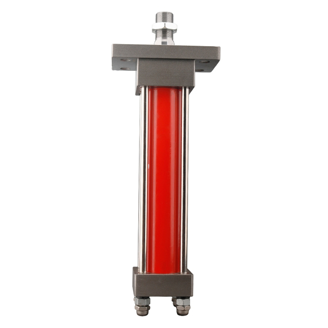
A cylinder that bangs at the end of its stroke rarely arrives as a neat cushioning question.
The operator usually reports a different problem. A loader bucket snaps back when it reaches the stop. A clamp closes smoothly, then hits the fixture hard enough to loosen bolts. A dump body shudders at full extension. On a small press, the rod reaches the end cap with a sharp metallic knock even though the movement looked controlled a moment earlier.
The first repair is often to reduce the main flow control. That may soften the impact, but it also slows the useful part of the stroke. Somebody then turns the relief valve down, changes the hose, or orders a larger hydraulic cylinder. The machine may become slower without becoming safer.
End-of-stroke shock is a motion problem before it is a cylinder-model problem. The moving mass has velocity, the load may be helping or resisting the motion, and the oil leaving the cylinder needs a controlled path. A cushion can manage that final part of the travel, but only when its type, direction, energy capacity, and adjustment suit the real machine.
This guide is for equipment builders, repair shops, maintenance teams, and buyers comparing a standard cylinder with a cushioned hydraulic cylinder. It explains what the cushion changes, how to estimate the demand with field data, why return flow matters, and when an external deceleration method is the better answer.
Quick Answer
Near the end of travel, a cushioned cylinder changes the route taken by the exhaust oil. The cushion spear or sleeve enters a close-fitting passage, so most of the oil can leave only through a much smaller opening. Pressure then builds on the exhausting side of the piston and checks the load before metal reaches the internal stop.
The cushion does not reduce speed through the entire stroke. It does not replace a relief valve, a load-holding valve, correct mounting, or a properly sized hydraulic flow control valve. It also works only when the cylinder travels far enough to enter the cushion zone.
For a purchasing decision, do not send only bore, stroke, and working pressure. Send the moving mass, cylinder orientation, actual extension and retraction speed, pump flow, load direction, frequency, oil temperature, and which end of the stroke is hitting. Those details decide whether cushioning is needed at the cap end, rod end, both ends, or somewhere outside the cylinder.
Why Trust This Guide
BLINCE's work covers more than the cylinder body. It includes HOB small round hydraulic cylinders, heavy-duty and compact cylinders, as well as the pumps, valves, hoses, and gauges around them. That wider view is useful on a hard-stop complaint: excessive flow, a rough spool transition, trapped pressure, worn pins, or a load accelerating downhill can all leave the cylinder taking the blame.
The engineering approach here also follows published cylinder-manufacturer guidance. Parker describes cushions as devices for absorbing energy at the stroke ends and notes that application data such as load, velocity, pressure, orientation, and mounting are needed for final selection. Its application engineering guide also distinguishes adjustable cushions from self-regulating designs rather than treating every cushion screw as interchangeable.
The purpose is not to replace the cylinder manufacturer's cushion-capacity chart. It is to help a buyer arrive with the right measurements, reject obvious mismatches, and avoid adjusting a symptom while leaving the cause untouched.
Start With the Impact Story, Not the Cushion Screw
Before changing an adjustment, write down what the machine does in plain language.
Note the direction first: rod out, rod in, or both. Then watch whether the piston completes its stroke or the machine structure arrives at a stop first. Run the same check cold and again after the oil is warm. If the noise appeared after a pump, valve, hose, rebuild, or attachment change, record that too; the timing often narrows the search faster than another adjustment.
Those details separate four very different situations:
The piston reaches the internal end stop with too much kinetic energy.
The machine hits an external stop before the internal cushion becomes active.
A valve or load creates a pressure shock even though piston speed is modest.
Mounting clearance, worn pins, or side load creates a mechanical knock that sounds hydraulic.
If the rod does not travel through the cushion zone, turning the cushion adjustment cannot fix the impact. The same principle appears in BLINCE's hydraulic cylinder installation guide: alignment, pins, bushings, stroke, and structure have to be checked together.
A useful field note might read:
The 100 mm bore cylinder lowers a 1,500 kg fixture. Retraction speed is approximately 0.25 m/s. The knock occurs only during the last 20 mm, after the oil reaches 55°C. The rod-end cushion is almost fully closed, and return pressure rises sharply near the stop.
That sentence tells a supplier far more than “need a cushioned cylinder.”
What Hydraulic Cylinder Cushioning Actually Does
In a typical built-in cushion, the piston approaches the cylinder head or cap and a cushion spear enters a matching bore. The main exhaust path closes progressively. Oil trapped in the end chamber must then leave through a restricted passage, often controlled by a needle-type cushion valve.
That restriction creates back pressure against the moving piston. The piston decelerates, and the kinetic energy of the moving mass is absorbed over a short distance instead of being released in one abrupt impact. A check-valve path commonly allows relatively free oil entry when the cylinder starts moving away from the cushioned end.
The MathWorks cylinder-cushion model illustrates the same basic mechanism: a cushion bush reduces the exhaust path near the end position while a separate controlled opening carries the remaining flow. The exact geometry, however, is manufacturer-specific.
The adjustment screw usually changes the exhaust restriction, not the point where cushioning begins. Closing it further increases the cushioning effect and usually lengthens the deceleration time. Opening it reduces back pressure and allows a faster approach to the end stop.
Too little restriction leaves a hard impact. Too much restriction can make the cylinder crawl, stop short, generate heat, or create a pressure peak in the cushioned chamber. The correct setting is not “fully closed plus half a turn.” It is the setting that decelerates the actual load smoothly while still allowing full stroke under realistic temperature and pressure.
Four Ways to Manage End-of-Stroke Energy
Method
Main advantage
Main limitation
Best fit
Who should avoid it
Built-in adjustable cushion
Compact and tunable on the machine
Works only near the designed stroke end; incorrect adjustment can create heat or incomplete stroke
Machines that stop before entering the cushion zone
Built-in fixed or self-regulating cushion
Repeatable and less dependent on operator adjustment
Less adaptable when mass, speed, or oil viscosity changes widely
Stable repetitive cycles
Applications with large variation in load or velocity
External deceleration or flow-control circuit
Deceleration point and rate can be placed outside the cylinder
Adds valves, plumbing, tuning, and failure points
Mid-stroke slowing, retrofits, special motion profiles
Buyers seeking the simplest low-cost circuit
Mechanical stop or shock absorber
Keeps structural positioning independent of the cylinder end cap
Must be sized for impact energy and mounted correctly
Machines needing a defined external stop
Systems expecting the cylinder cushion to hold or position the load
These choices are not quality grades from weak to strong. They solve different motion problems.
An integral cushion keeps the plumbing tidy and leaves most of the working stroke alone. Its useful range, however, is close to the endpoint. Moving the deceleration function into an external valve gives the designer an earlier slowing point, but it also introduces a spool, pilot signal, and extra flow path that must all behave consistently.
A mechanical stop answers the question "where must the machine stop?" It does not answer "how will the moving energy be removed?" A shock absorber or hydraulic deceleration stage may still be needed, and the cylinder's internal end cap should not become the everyday impact surface unless the machine and cylinder were designed for that duty.
The Three Numbers That Decide Whether Cushioning Is Easy or Difficult
Three measurements should be collected before a cushion is specified:
Moving mass, including tooling, linkage, payload, piston, rod, and attached hardware
Actual piston velocity immediately before the cushion zone
Load direction relative to motion, especially whether gravity assists the movement
The horizontal kinetic energy is:
E_kinetic = 0.5 × m × v⊃2;
where:
E is energy in joules
m is moving mass in kilograms
v is velocity in metres per second
Take a shop example: the carriage, fixture, and tooling weigh 1,500 kg together. A timed video puts the approach speed at 0.25 m/s. For horizontal travel, the worksheet reads:
E_kinetic = 0.5 × 1,500 × 0.25⊃2; = 46.9 J
Turn that carriage into a lowering load and the worksheet changes sharply. If deceleration happens across the last 30 mm, gravity continues doing work while the cushion is trying to stop the movement:
E_gravity = m × g × s
E_gravity = 1,500 × 9.81 × 0.03 = 441.5 J
The vertical-down case is therefore not a 46.9 J problem. Before accounting for hydraulic drive pressure and losses, the moving system already presents about 488 J across that short distance. This is why a cushion that feels comfortable on a horizontal bench may be inadequate when the same cylinder lowers a heavy fixture.
These calculations are screening tools, not a product guarantee. Final selection must use the cylinder manufacturer's cushion-energy data and the real load geometry. Parker's hydraulic cylinder cushioning data explicitly modifies the energy calculation for inclined and vertical movement.
Cylinder Speed Must Be Calculated From Flow and Area
Operators often estimate speed by watching the rod. A quotation needs a better number.
For extension of a double-acting cylinder:
v_extension = Q_in / A_piston
For retraction:
v_retraction = Q_in / A_annular
where:
Q is actual inlet flow in m³/s
A_piston = π × D⊃2; / 4
A_annular = π × (D⊃2; - d⊃2;) / 4
D is bore diameter
d is rod diameter
Consider a 100 mm bore cylinder with a 56 mm rod receiving 80 L/min.
The bore gives 7,854 mm² of full piston area; subtracting the rod leaves 5,391 mm² on the annular side. Put 80 L/min into the cap end and the calculated extension speed is 0.170 m/s. Send the same flow to the rod end and the smaller working area raises the retraction speed to about 0.247 m/s.
The retraction speed is roughly 45% higher even though pump flow has not changed. A buyer who specifies “80 L/min at both ends” but does not state bore and rod diameter leaves out the number that determines piston velocity and cushion demand.
Actual speed will be lower because of leakage, valve pressure drop, pump efficiency, and load behavior. Measure it under the condition that produces the impact instead of relying only on calculated pump delivery.
Return Flow Can Be Higher Than Pump Flow
The cushion controls oil leaving the cylinder, so exhaust flow matters as much as inlet flow.
Follow the oil out of that 100/56 mm cylinder. With 80 L/min entering the cap end, the rod-side line carries only the volume displaced by the annular area:
The cap-side line now has to clear 116.6 L/min through its port, fittings, hose, valve, and shared return. The cushion adds an intentional restriction at the very end. If the return line was chosen from the 80 L/min pump label alone, the resulting back pressure should not be surprising.
The hydraulic tubing selection guide is relevant here because inside diameter, fittings, bends, and routing affect the exhaust path. A hose thread can fit while its internal passage is still too small.
Cushion Pressure Is Not the Same as Main Working Pressure
The pump outlet gauge cannot show the whole event. The cushion creates pressure in the exhaust chamber, often for a short time near the end of travel. If the only gauge is at the pump, the technician may see normal supply pressure and miss the pressure acting against the opposite side of the piston.
Install suitable test points near both cylinder ports when practical. Record pressure through the complete stroke, not just at rest. The BLINCE guide to hydraulic pressure gauge placement explains why one local reading cannot reveal losses or trapped pressure elsewhere.
If cap-end supply pressure is 160 bar while rod-end cushion pressure rises to 90 bar, the cylinder does not receive the same net extending force as a circuit with a near-zero rod-end pressure. The exact force balance uses piston and annular areas, not a simple subtraction of gauge readings.
High cushion pressure is not automatically proof of a bad cylinder. It may show that the adjustment is too restrictive, the load is too fast, the exhaust hose is small, the directional valve passage is undersized, or the return manifold is already pressurised.
Cap-End and Rod-End Cushions Do Different Work
A cap-end cushion acts near the end of retraction or extension depending on the manufacturer's naming convention and cylinder layout, so the quotation should identify the physical motion rather than relying only on “head” and “cap.” State whether the rod is moving out or in when the impact occurs.
The two ends also have different hydraulic areas. A rod-end cushion may have less available annular area, while the cap end sees full piston area. Drive pressure, load direction, return pressure, and the cushion geometry all change the energy that can be managed.
If the machine only hits hard at full extension, buying cushioning at both ends may add cost without solving another problem. If a reciprocating machine reverses at both endpoints with meaningful mass and speed, two-end cushioning may be justified.
The ROB heavy-duty tie-rod cylinder and other BLINCE cylinder families can be reviewed against load, stroke, mounting, pressure, and customization requirements. Cushion availability and configuration must be confirmed for the exact series and size; it should never be assumed from a category photo.
How to Adjust a Hydraulic Cylinder Cushion
Adjustment should follow the cylinder manual and site safety procedure. The moving load and stored hydraulic pressure can be dangerous. Isolate energy before touching an adjuster, and keep personnel outside the swept area during testing.
A practical commissioning sequence is:
Confirm the cylinder, cushion direction, ports, and adjustment locations.
Bleed air and bring the oil to representative working temperature.
Begin with the manufacturer's recommended setting, not a guessed number.
Run the cylinder at reduced load and speed.
Change the adjustment in small recorded increments.
Increase speed and load gradually while watching both port pressures.
Confirm that the piston reaches full stroke without a hard impact or long dwell.
Repeat enough cycles to expose temperature-related changes.
Lock or protect the adjustment where the design provides that feature.
Turning an adjustable cushion clockwise commonly increases restriction, but that convention is not universal enough to replace the manual. Do not force the screw against its seat. A damaged needle or seat can make repeatable adjustment impossible.
Parker's MA3 hydraulic cylinder operating instructions describe the aim clearly: achieve full stroke without striking the cap too hard. That is a better acceptance criterion than “the cylinder became quiet.”
Why a Cushion May Work Cold and Fail Hot
Oil viscosity changes with temperature. Cold oil creates more resistance through a small cushion passage, so the cylinder may slow strongly or stop before full stroke during startup. As the oil warms and viscosity falls, the same adjustment may provide less damping and allow a harder impact.
Internal leakage also tends to become more visible with hot, thinner oil. A worn piston seal can change speed and pressure on both sides of the piston. A flow-control setting that looked stable during a five-minute test may drift after an hour.
Record at least three conditions: cold startup, normal working temperature, and the hottest expected continuous cycle. If the adjustment only works at one temperature, the application may need a different cushion profile, external control, lower approach speed, or a review of oil grade.
Do not treat every hot cylinder as a cushion problem. Relief flow, valve throttling, undersized return lines, and a restricted hydraulic oil cooler can add heat elsewhere. The oil cooler sizing guide helps separate heat removal from heat generation.
When the Directional Valve Creates the Shock
Some impacts occur before the piston reaches the cushion zone. A directional valve that closes an actuator port abruptly can stop a moving mass by trapping oil. A spool transition can also connect or block ports in a way that creates a pressure pulse.
If the noise occurs when the lever is released mid-stroke, the cylinder cushion is not the first suspect. Check the hydraulic directional control valve, spool center, metering notches, pilot timing, and load-holding circuit.
The BLINCE directional control valve selection guide explains why valves with similar ports can behave differently during neutral and transition. A cushion cannot correct a valve that sends the wrong pressure path to the actuator.
For suspended or overrunning loads, a counterbalance or load-control valve may be required. Do not expect an end cushion to hold a load after motion stops. Cushioning is for deceleration, not static load security.
When an External Deceleration Circuit Is Better
An external solution deserves consideration when:
The machine must slow before the built-in cushion zone
The stopping position varies
The cylinder does not use its full stroke
Approach speed must change with product size or recipe
A sensor and proportional valve already control motion
The cylinder cannot be replaced easily
An external flow-control or proportional circuit can begin deceleration at a sensor-defined position. It may offer a longer, smoother ramp than a short built-in cushion. It can also be tuned without changing the cylinder.
The tradeoff is complexity. Sensors, electrical logic, proportional valves, pilot lines, and software create more possible faults. A simple machine with a stable load may be more reliable with a correctly sized integral cushion.
Do not install a simple throttle and assume the speed will remain constant under changing load. A pressure-compensated flow control may be required. For a detailed comparison, see the BLINCE article on hydraulic flow control valve troubleshooting.
Equipment-Specific Checks
Industrial Presses and Clamps
A press or clamp often needs fast approach, controlled working speed, and gentle stopping. The cushion should not be used to compensate for a cylinder that is too fast throughout the entire stroke. Separate approach flow, work flow, and end deceleration where cycle control matters.
Confirm whether the fixture stops the load before the piston reaches full stroke. If it does, an internal cushion may never engage. A CX compact hydraulic cylinder can suit space-limited machinery, but compact packaging does not remove the need to review energy, guidance, and external stops.
Agricultural Machinery
Agricultural cylinders work with changing loads, dust, temperature swings, worn pins, and field repairs. A cushion adjustment that was correct with an empty implement may be inadequate when the hopper or attachment is full.
Inspect pin clearance and linkage geometry before blaming the cushion. Contaminated oil can block a small cushion passage, so the hydraulic contamination control guide is relevant when adjustment becomes inconsistent.
Construction and Material Handling Equipment
Booms, buckets, lift tables, and stabilizers can create overrunning loads. Gravity may add far more energy than the horizontal kinetic calculation suggests. Record whether the load is lifting or lowering and whether a load-control valve is installed.
A HSG hydraulic cylinder or heavy-duty tie-rod cylinder should be selected from actual structure, pressure, stroke, mounting, and duty data. Cushioning is one option inside a larger machine-safety review, not a substitute for it.
Repetitive Industrial Automation
High cycle count changes the commercial decision. A small impact repeated every six seconds can loosen fasteners, mark tooling, and shorten seal life even when a single cycle looks harmless.
Record cycles per minute, hours per shift, mass variation, working temperature, and acceptable stop time. A fixed self-regulating cushion may reduce adjustment work, while an adjustable cushion may suit commissioning. For variable recipes and demanding positioning, a controlled external deceleration profile may justify the added components.
Who Should Not Buy a Cushioned Cylinder Yet?
Do not order a cushioned replacement cylinder as the first step if any of the following is true:
The machine hits an external stop before the cylinder reaches full stroke
The noise occurs during valve shifting in mid-stroke
Pins, bushings, or brackets are visibly worn or misaligned
The cylinder moves slowly with a light load and has little end-of-stroke energy
The real need is precise mid-stroke positioning
The circuit lacks required load-holding or overrun control
The hose and valve cannot carry the exhaust flow
No one has measured speed, load, or oil temperature
These buyers may need a mounting repair, valve review, external deceleration circuit, mechanical stop, or flow correction before choosing another cylinder.
A cushioned cylinder is a poor purchase when it is being asked to hide a structural or circuit defect. It becomes a good purchase when the endpoint, moving energy, flow path, and adjustment method are understood.
Practical Checklist Before Ordering
Question
Minimum useful information
Why it changes the choice
Which motion hits hard?
Rod extending, rod retracting, or both
Determines cushion end
Does the cylinder reach full stroke?
Measured stroke and external stop position
Confirms whether the cushion can engage
How fast is the piston?
Timed travel or measured m/s under load
Determines kinetic energy
What mass is moving?
Load, tooling, linkage, rod, and carriage
Determines deceleration demand
Is gravity helping the motion?
Horizontal, lifting, or lowering angle
Adds or subtracts energy
What are the cylinder dimensions?
Bore, rod, stroke, closed length, mounting
Determines speed, force, and fit
What is actual flow?
Pump flow and valve flow at working pressure
Determines speed and exhaust flow
What are both port pressures?
Pressure traces near the impact
Reveals cushion and return pressure
What is the oil condition?
Grade, temperature range, cleanliness
Changes restriction and repeatability
How often does it cycle?
Cycles/minute and hours/shift
Changes heat and fatigue exposure
If half these answers are unknown, a preliminary selection can still begin. It should not be presented as a final cushion validation.
Where Cushioning Jobs Commonly Go Wrong
The Machine Is Quiet, So the Adjustment Must Be Right
Silence does not prove correct deceleration. An over-restricted cushion may create high back pressure, heat, or a long dwell before full stroke. Record pressure and stroke time while adjusting.
Mistake 2: Slowing the Entire Machine to Fix the Final 20 mm
Reducing main flow can soften impact but sacrifices cycle time through the full stroke. If only the endpoint is wrong, use a method that targets the endpoint.
Mistake 3: Ordering Cushions on Both Ends Without Checking the Motion
One-end cushioning may be enough. Adding unused options increases cost and can complicate service without improving the application.
Mistake 4: Ignoring Return Flow
On retraction, the cap-end exhaust can exceed pump delivery because the two piston areas are different. Trace that calculated volume through the actual hose bore, elbows, fittings, valve gallery, and return manifold.
Expecting the Cushion to Hold the Load
A cushion decelerates motion near the stroke end. It does not securely hold a suspended load in neutral. Use the correct load-control architecture.
Mistake 6: Adjusting With Cold Oil Only
Viscosity changes what the small exhaust opening does. A setting made during a cold, empty cycle deserves another test after the oil is warm and the real load is attached.
Overlooking Dirt in a Very Small Passage
A small particle can disturb a needle, check valve, or cushion passage. If adjustment changes from cycle to cycle, inspect oil cleanliness and the component before ordering another cylinder.
Mistake 8: Assuming the Product Photo Confirms Cushioning
Cylinder series often have many options. Confirm cushion direction, adjustment type, port location, seals, pressure, and dimensional code for the exact ordered configuration.
A Quote Request That Gives Engineering Something to Work With
Instead of writing:
Quote 100 × 56 × 800 cushioned cylinder.
send a short technical note:
We are lowering a 1,500 kg fixture with a 100/56 × 800 mm cylinder. Loaded retraction takes 3.2 seconds, then the machine hits hard during the final 25 mm. Pump delivery is about 80 L/min and operating pressure reaches 160 bar. Oil normally runs at 50–60°C. A counterbalance valve is installed; cap-end oil returns through a 3/4-inch hose into a shared manifold. The piston does complete its internal stroke. Please check cap-end cushion capacity and tell us which two-port pressure traces or mounting drawings you need.
That request identifies mass, direction, speed, dimensions, flow, pressure, temperature, return path, and the end requiring attention. It allows a supplier to challenge the hose size, cushion capacity, valve arrangement, or cylinder choice before metal is ordered.
For a BLINCE review, include photos of the existing cylinder, nameplate, mounting pins, hose routing, ports, external stops, and any cushion adjusters. The MOB cylinder series, HOB, ROB, CX, and HSG families cover different installation envelopes; the correct series still depends on verified working data.
FAQ
What happens inside a cushioned hydraulic cylinder?
As the piston nears one end, a spear or sleeve closes the normal exhaust route. The remaining oil is metered through a smaller passage, and the pressure on that side checks the piston before it reaches the stop.
What is a sensible way to adjust the cushion?
Use the cylinder manual and isolate stored energy before touching the adjuster. Start at the stated baseline, warm the oil, and make one small, recorded change at a time. Bring speed and load up gradually while checking that the piston completes its stroke and that pressure does not climb simply because the impact became quieter.
Will closing the cushion screw always soften the stop?
Closing the screw often reduces the exhaust opening, although the direction and usable range depend on the design. Past a certain point, extra restriction produces crawl, heat, high pressure, or a piston that stops short. The needle should never be forced into its seat.
Does a cushion slow the cylinder through its whole stroke?
No. A built-in end cushion normally acts only near the end position. Use a flow-control or motion-control solution if speed must be managed through the full stroke or at a mid-stroke position.
Can cushioning replace a relief valve?
No. A relief valve limits system pressure. A cushion manages deceleration near an endpoint. They perform different safety and control functions.
Can cushioning hold a suspended load?
No. A cushion is not a certified load-holding device. Suspended or overrunning loads may require counterbalance valves, pilot-operated check valves, mechanical locks, and other machine-safety measures.
Why does the cylinder still hit hard with the cushion fully closed?
Possible causes include excessive speed or mass, insufficient cushion capacity, a damaged spear or needle, internal leakage, contamination, an external stop reached before the cushion zone, or a valve-generated shock outside the cushion event.
Why does the cylinder stop before full stroke?
The cushion may be over-restricted, oil may be cold, available pressure may be low, return pressure may be high, or the load may change near the endpoint. Check both port pressures and the mechanical stop before opening the adjuster blindly.
Do I need cushioning at both ends?
Only if meaningful impact energy exists at both endpoints. State which motion hits, the speed in each direction, and whether the load helps or resists movement.
Should I specify an adjustable cushion instead of a fixed one?
Choose it because the application needs tuning, not because adjustment sounds like an upgrade. Variable loads and commissioning work can justify an adjuster. A stable, repetitive machine may be easier to keep consistent with a correctly selected fixed or self-regulating design.
How does oil temperature affect cushion adjustment?
Cold viscous oil creates more restriction; hot thinner oil creates less. A setting that works cold may allow a harder impact when hot, while a setting tuned hot may stop the cylinder short during cold startup.
What data should I send for a cushioned cylinder quotation?
Send bore, rod, stroke, mounting, ports, pressure, actual flow, moving mass, orientation, speed in both directions, cushion end, working temperature, cycle rate, valve arrangement, hose size, and photos or drawings.
Final Takeaway
Hydraulic cylinder cushioning should begin with the moving load, not the adjustment screw.
Time the approach, name the end that hits, and verify that the piston actually enters its cushion zone. Work out the area ratio and follow the expected return flow through the real plumbing. With both port pressures recorded at working temperature, the choice between an integral cushion, external deceleration, and a mechanical stop becomes much less speculative.
For a BLINCE custom hydraulic cylinder review, the useful evidence is not a model number alone. Send the cylinder dimensions, moving mass, a full-cycle video, flow and two-port pressure readings, oil temperature, mounting drawing, and the point where the impact begins. We can then read the cylinder alongside the pump, valve, hoses, fittings, and machine structure.
The goal is not merely to make the final stroke quieter. It is to remove the energy in a controlled way without adding unnecessary heat, delay, or repeat failure.
This article is a general engineering guide. Final component selection should be based on machine drawings, measured hydraulic data, working conditions, safety requirements, and confirmation from a qualified hydraulic engineer or supplier.
Blince Hydraulic Team
Blince Hydraulic is an industry-leading company dedicated to precision-engineered fluid power manufacturing and custom hydraulic solutions. Backed by decades of deep field expertise in industrial machinery and thousands of successful global deployments, our engineering team focuses entirely on high-performance hydraulic component manufacturing, including specialized orbital motors, high-pressure travel drives motor, and robust directional control valves. Our production infrastructure utilizes state-of-the-art multi-axis CNC machining systems and is fully ISO 9001 certified to guarantee repeatable volumetric accuracy across every single manufacturing run.
We deliver fast, highly dependable, and cost-efficient hydraulic solutions to heavy industry distributors, machinery OEMs, and maintenance crews across more than 150 countries. Whether your active project calls for a small-volume batch of customized shaft profiles or a large-scale production run of severe-duty cast iron gear pump, we configure our flexible production schedules to meet your target lead times with total pricing predictability. Partnering with Blince means securing maximum system efficiency, elite material quality, and uncompromised fluid power professionalism.
To learn more about our complete product lineup, visit our official website: www.blince.com.