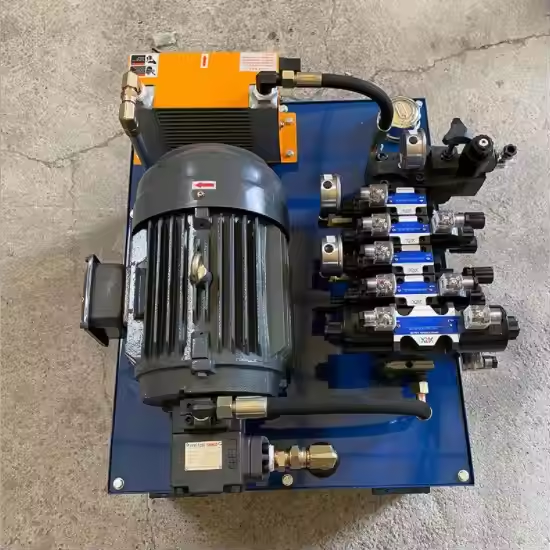
A hydraulic power unit can reach the relief setting and still be wrong for the machine.
The gauge climbs to 160 bar. The cylinder moves, but it takes twelve seconds instead of seven. After forty minutes, the tank is hot, the electric motor current is higher than expected, and the operator begins pausing between cycles. The first suggestion is often a larger pump. The second is a larger oil cooler. Neither suggestion answers the useful question: where is the available power going?
The missing flow may begin at the pump inlet. It may be lost through a small directional valve, a filter, a long return hose, or a relief valve that remains open during part of the cycle. The electric motor may be large enough for the average load but too small for repeated starts. The reservoir may hold enough oil to cover the suction port while providing too little time for air to leave the fluid. A custom hydraulic power unit has to be selected as a working circuit, not as a tank with a motor bolted on top.
This is the sort of sizing job that usually lands on several desks. Maintenance knows when the machine slows down. Purchasing has the old model number. The builder knows how much space is left beside the frame. None of those facts is enough on its own. Put them together, however, and the pump, electric motor, tank, valves, filters, and cooler can be discussed before a supplier commits to a layout that is expensive to change.
Start With the Machine Cycle, Not the Power Unit Catalog
Begin with a stopwatch and the machine, not a pump catalogue. Follow one complete cycle. A press might cross most of its travel quickly, slow near the workpiece, hold force for eight seconds, then come home almost unloaded. A lift may start hard but move only six times in an hour. A conveyor is the opposite sort of problem: moderate pressure, perhaps, but no long rest. Their peak gauge readings could match while their power units need quite different motors, tanks, and cooling arrangements.
Record each actuator separately. For a cylinder, note bore, rod diameter, stroke, load direction, required travel time, and the hardest point in the linkage. For a rotary drive, note displacement, target rpm, starting torque, case-drain arrangement, and whether the load can overrun the motor. The hydraulic pump and motor matching guide explains why speed, torque, return pressure, and oil temperature have to be read together.
Then write down which functions operate at the same time. A 25 L/min steering branch and a 35 L/min clamp branch do not necessarily require a 60 L/min pump if the control sequence prevents simultaneous operation. The same two branches may require all 60 L/min if the operator can use both together. The schematic, valve logic, and PLC sequence decide which statement is true.
For field work, one plain sentence is more valuable than a polished part-number request:
The unit extends an 80 mm bore cylinder through 500 mm in 7 seconds, holds a 22 kN load for 10 seconds, retracts unloaded, and repeats four times per minute. Oil reaches 63 C after one hour, while pump outlet pressure is 160 bar and return pressure is 9 bar during extension.
That note already gives a supplier a place to start. "Quote a 7.5 kW hydraulic power pack" does not.
What a Hydraulic Power Unit Actually Includes
On the shop floor, "power unit" may mean anything from a motor-pump set on a small tank to a complete hydraulic station with a manifold and control cabinet. The useful boundary is functional: it stores and conditions the oil, drives the pump, limits pressure, and sends controlled flow toward the machine. Directional valves, filters, a filler breather, level and temperature indication, test couplings, an accumulator, a heater, or a cooler may be fitted when the duty calls for them. They are not required merely to make the assembly look complete.
One change tends to move several other limits. Add pump displacement and the valve block, filter, cooler, hoses, and tank return must carry the extra oil. Reduce tank height to clear a guard and the suction port may sit too close to returning, aerated fluid. Raise the relief setting and shaft torque rises with it; so does the possible load on the cylinders, pipework, and machine structure. That chain of effects is where a compact, tidy-looking unit can become a poor working unit.
Required actuator flow, pressure, control method, speed, and duty
Copying the old pump or selecting by maximum pressure
Electric motor
Pressure-flow demand, efficiency, starting method, overload, and duty
Using hydraulic power as the motor nameplate value
Reservoir
Oil volume changes, heat, air release, suction conditions, and service access
Applying one universal tank-to-flow ratio
Valve and manifold
Function sequence, flow, pressure drop, center condition, and safety
Matching only port thread and spool count
Filtration
Component sensitivity, ingression risk, pressure drop, and maintenance
Installing the finest element that fits
Cooler or heater
Calculated or measured heat load, ambient condition, and oil range
Buying by pump flow alone
Instrumentation
Commissioning and failure decisions that must be made
Installing one gauge at the pump outlet
Step 1: Convert Actuator Motion Into Required Flow
Flow mainly controls actuator speed. Pressure develops in response to resistance and load. Keeping those two jobs separate prevents one of the most common mistakes in power-unit selection: increasing the relief setting because a cylinder is slow.
For a double-acting cylinder, first calculate the area that actually sees pressure on the working stroke:
A_piston = pi x D^2 / 4
The rod-side annular area is:
A_annular = pi x (D^2 - d^2) / 4
Where D is bore and d is rod diameter. Required flow follows from area and speed:
Q = A x v
The field version of the calculation is less abstract: find the oil volume needed to fill the working chamber, then ask how quickly that volume has to arrive. Run the numbers twice. Extension uses the full bore area; retraction uses the smaller annular area around the rod. With one fixed flow, a double-acting hydraulic cylinder will therefore commonly return faster than it extends.
Cylinder Example: 80 mm Bore, 500 mm Stroke
For an 80 mm bore, the full piston area works out to roughly 5,026.5 mm2. Move that area through a 500 mm stroke and the cap end takes about 2.51 liters. That is the volume which must arrive after the valve shifts, not merely the volume shown in the pump catalogue.
To move those 2.51 liters in 7.2 seconds requires about 20.9 L/min on paper. A pump marked 20 L/min is already short before leakage is counted. Valve transition, acceleration, warm-oil leakage, and a second function can take another share. In other words, 20.9 is a useful target at the cylinder port, not permission to order the nearest nominal pump.
For a hydraulic motor, the same volume-and-time idea appears as displacement per revolution:
Q_theoretical (L/min) = displacement (cm3/rev) x speed (rpm) / 1000
A 250 cm3/rev motor at 80 rpm consumes 20 L/min in the ideal calculation. The real supply has to cover leakage as well. Deliver only 18 L/min after pump wear and valve losses and the shaft cannot hold the calculated speed; increasing pressure will not replace the missing oil.
Branch totals need a quick reality check. If two cylinders are interlocked and never move together, adding both peak flows oversizes the source. If an operator can feather both spools at once, ignoring one branch does the opposite. Priority steering, regenerative circuits, accumulators, and variable pumps make the nameplate sum even less reliable; for those machines, trace the schematic through the actual sequence.
Step 2: Choose Pump Displacement From Real Drive Speed
For a fixed-displacement pump, theoretical delivery is:
Actual flow can be estimated by multiplying by volumetric efficiency:
Q_actual = Q_theoretical x volumetric efficiency
Take a 16 cm3/rev HGP series hydraulic gear pump driven at 1,450 rpm. Multiplication gives 23.2 L/min before internal leakage. Using 90 percent volumetric efficiency as a temporary estimating value brings the expected delivery back to 20.9 L/min.
That 90 percent figure is a worksheet assumption, not a promised BLINCE rating. Pump construction, pressure, speed, oil viscosity, temperature, and wear all move it. Final selection should come from the curve for the exact pump. At this stage, the estimate is only answering a rough question: is 16 cm3/rev plausible, or are we plainly in the wrong size range?
Check the speed at the pump shaft, not the number remembered from the motor brochure. A 50 Hz induction motor does not normally turn at its 1,500 rpm synchronous speed once loaded. Engines wander through a wider range, and PTO ratios are often passed along incorrectly. A design based on 1,800 rpm that actually receives 1,450 rpm loses about one-fifth of its theoretical flow before pump leakage enters the discussion.
Fixed or Variable Displacement?
A fixed gear pump makes sense when the machine wants roughly the same delivery each cycle and the circuit has an honest way to unload it. It is inexpensive and familiar to service. Trouble starts when most of that fixed flow spends long periods squeezed through a metering edge or dumped across relief while the actuator barely moves.
A variable-displacement axial piston pump can back away from full displacement when the control tells it demand has fallen. That saves wasted flow only when the control is set up correctly. Load-sense plumbing, compensator settings, clean oil, and an open case drain become part of commissioning; the piston-pump case-drain guide covers one of the less visible failure paths.
Selection question
Fixed-displacement starting point
Variable-displacement starting point
Flow demand
Fairly stable or handled by simple sequencing
Changes widely through the cycle
Control complexity
Lower
Higher
Idle loss
Can be high if flow is throttled or sent over relief
Can be lower when the pump destrokes correctly
Contamination sensitivity
Often more tolerant, depending on pump type
Controls and close clearances need stronger discipline
Purchase cost
Usually lower
Usually higher
Commissioning data
Rotation, inlet, relief, flow, pressure
Adds compensator, load-sense, case drain, control settings
Best reason to choose
Honest match to a simple duty
Real energy or control benefit in a changing duty
Do not choose a variable pump only because it sounds more advanced. Do not choose a gear pump only because it is familiar. The machine cycle should make the decision.
Step 3: Calculate Hydraulic Power Before Choosing Motor kW
Once flow has been tied to speed, pressure and flow can be combined to estimate hydraulic output:
P_hydraulic (kW) = pressure (bar) x flow (L/min) / 600
For the running point used here, 160 bar and 20.9 L/min give:
160 x 20.9 / 600 = 5.57 kW
The motor cannot be sized at 5.57 kW exactly. Part of its shaft power is lost in the pump and drive. Using 85 percent overall efficiency as an early estimate gives:
P_motor_input = 5.57 / 0.85 = 6.55 kW
A 7.5 kW motor may be a reasonable starting point for this example. It is not an automatic final choice. Starting under load, cold-oil viscosity, relief operation, voltage and frequency, service factor, ambient temperature, altitude, enclosure, starts per hour, and the actual pump efficiency still matter.
Motor current should be recorded under the real duty. A power unit that runs comfortably during one cylinder stroke may trip after repeated starts or after the oil warms and the machine begins holding pressure longer. The hydraulic calculation does not replace the electrical design; it gives the electrical designer a load case to check, while the pump coupling alignment guide covers the mechanical checks between the two machines.
Peak Power Is Not the Same as Continuous Power
A lift may need 160 bar for five seconds and then rest for two minutes. A press may use high pressure only at the end of the forming stroke. A conveyor can demand moderate pressure continuously. Nameplate selection should reflect how long the motor carries each load, whether it can cool between cycles, and whether the machine starts while the hydraulic circuit is unloaded.
If the pump starts against pressure, review the valve center, unloading arrangement, check valves, and trapped pressure. An oversized motor can hide a poor start circuit, but it does not remove the pressure spike or mechanical shock. The hydraulic check valve selection guide is relevant when pressure remains trapped after shutdown.
Worked Selection Example: A Small Industrial Lifting Unit
Consider a lifting fixture with these preliminary requirements:
80 mm bore, 45 mm rod, 500 mm stroke;
22 kN maximum external load during extension;
7.2-second target extension time;
four complete cycles per minute during a 20-minute production batch;
160 bar maximum intended working pressure;
a 400 V, 50 Hz, three-phase electrical supply;
indoor service, normally 15-35 C around the unit.
The cap end holds about 2.51 liters over the stated stroke. Spreading that volume over 7.2 seconds produces the 20.9 L/min target. A 16 cm3/rev pump at 1,450 rpm gives 23.2 L/min theoretically and, with the temporary efficiency allowance, lands close to 20.9 L/min.
If all 20.9 L/min were delivered at 160 bar, the hydraulic output would be 5.57 kW. Allowing for the assumed losses raises the shaft requirement to 6.55 kW. That puts a 7.5 kW motor on the shortlist, but not yet on the order: cold starting, starts per hour, overload, and the real pressure trace still have to agree.
The force check also matters. At 160 bar, an 80 mm bore gives about 80.4 kN theoretical extension force, far above the stated 22 kN load. That difference is a warning, not a benefit. Either the actual working pressure will be much lower, the linkage has a large mechanical disadvantage, or the initial data are incomplete. A correct supplier should ask which statement applies before setting the relief valve.
This example shows why flow and pressure should not be copied from separate catalog rows. The speed target points toward about 21 L/min. The load may need much less than 160 bar. The correct motor and relief setting can only be finalized after the real force and linkage are confirmed.
Step 4: Size the Reservoir Without Worshipping One Ratio
The familiar shortcut is to make reservoir volume a multiple of pump flow. Ratios such as two, three, or five times pump flow are often used during early planning. They are not universal design rules. A 60-liter reservoir may be generous for one 20 L/min intermittent unit and inadequate for another unit with continuous throttling, poor airflow, a large differential-cylinder volume, and heavy contamination exposure.
The reservoir has several jobs. It must keep the suction inlet covered through every actuator position, hold the oil displaced by cylinders and accumulators, allow space for thermal expansion, slow the returning oil enough for air and contamination management, and give maintenance staff access to clean and inspect it. It also contributes surface area and oil mass to thermal control.
Start by calculating the maximum change in system oil volume. A large single-rod cylinder stores different quantities on the cap and rod sides. Several cylinders can extend together. An accumulator may release and recover a meaningful oil volume. The tank must stay within safe minimum and maximum levels through the complete sequence, not only when every actuator is retracted.
Then look at return flow. Cylinder retraction can send more oil back to the reservoir than the pump is supplying because the rod reduces annular volume. A regenerative circuit can create another flow pattern. The return diffuser, filter, cooler, and port layout must handle that peak without turning the tank into a foam generator.
A Better Reservoir Screening Table
Condition
What pushes reservoir size upward
What may allow a compact tank
What must still be verified
Continuous industrial duty
Heat load, long run time, air release
Effective cooler and efficient circuit
Stable oil temperature and deaeration
Intermittent lift or clamp
Large cylinder volume change
Long rest time between cycles
Minimum level at full extension
Mobile equipment
Tilt, vibration, limited space
Purpose-designed compact layout
Suction coverage on slopes and return aeration
High-speed return flow
Foam risk and short residence time
Diffusers and careful tank geometry
Peak return velocity and baffle layout
Dirty or humid environment
Service and contamination control
Sealed filling and good breather location
Filter access and water removal
Variable-displacement unit
Controls may reduce idle heat
Lower average flow
Case drain, standby loss, and transient return flow
A preliminary range can begin with roughly two to five liters of reservoir volume per L/min of pump flow for many conventional units, but the final number must be justified by the factors above. Treat the ratio as a conversation starter, not as proof.
The suction and return ports should be separated enough to prevent hot, aerated return oil from going straight back into the pump. Internal baffles, diffusers, and sensible port positions can help, while poor geometry can defeat a large tank. The hydraulic tank breather guide covers how oil-level movement also changes the required air path.
Step 5: Find the Heat Source Before Adding a Cooler
Every loss becomes heat. Pump leakage, motor inefficiency, valve pressure drop, relief flow, undersized hoses, tight couplers, filter restriction, and return back pressure all consume power without producing useful motion.
A quick heat estimate for a known pressure drop is:
Heat loss (kW) = pressure drop (bar) x flow (L/min) / 600
If 20 L/min crosses a valve with a 40 bar pressure drop, approximately 1.33 kW is being converted into heat at that condition. If the same loss continues for most of the shift, it is not a small thermal detail.
Relief flow is more severe. Sending 20 L/min across a 160 bar relief setting represents about 5.33 kW of hydraulic power turning mainly into heat. A cooler may remove part of that heat, but the better first repair is often to stop the circuit from sitting on relief.
Measure oil temperature as a trend. Record tank temperature, ambient temperature, cycle state, pump pressure, return pressure, and motor current at regular intervals until the unit reaches a stable condition or exceeds the allowed range. One reading taken after the machine has been switched off cannot show where the heat was produced.
When real heat rejection is needed, size the cooler from heat load, oil flow, allowable oil temperature, ambient air or water condition, contamination, fan power, and pressure drop. The hydraulic oil cooler sizing guide explains why a larger core is not automatically a better circuit.
For units that need forced-air cooling, a product such as the BLINCE AD series hydraulic oil cooler should be selected against the calculated heat rejection and actual oil path. Do not use the pump's nominal flow as the only cooler specification.
Step 6: Check Valve Capacity and Control Logic
The valve block decides where the pump flow goes when the actuator moves, stops, holds, or changes direction. A well-sized pump can look weak behind an undersized spool. A correctly sized electric motor can run hot if the valve center keeps the pump loaded in neutral.
For each valve, confirm rated flow, working pressure, internal pressure drop, spool function, center condition, actuation method, voltage, manual override, and drain or pilot requirements. The directional control valve selection guide shows why matching the port pattern is not enough.
Pressure control also needs a hierarchy. The main relief protects the source circuit. A reducing valve may limit one branch. A counterbalance valve may control an overrunning load. A sequence valve may start the next function only after the first one develops pressure. If their settings overlap carelessly, the power unit can chatter, heat, or perform functions in the wrong order.
Flow control deserves the same treatment. Metering 30 L/min down to 8 L/min with a fixed pump can waste a large amount of power unless unused flow is unloaded or used elsewhere. Before specifying a bigger reservoir and cooler, compare the circuit with the hydraulic flow control valve troubleshooting guide.
Step 7: Design the Suction and Return Paths as Parts of the Unit
The pump cannot deliver oil it cannot receive. A long suction hose, small fitting, closed valve, dirty strainer, collapsed liner, high cold-oil viscosity, or poor tank outlet can starve a pump even while the reservoir looks full.
Keep the suction path short and generous, using the pump manufacturer's inlet limits rather than a convenient hose size. Avoid unnecessary elbows and reducers. Make sure the line does not rise into an air pocket. If the pump is mounted above the oil level, priming and allowable inlet conditions need explicit confirmation.
The return side should be checked for peak flow, not only pump delivery. Filters, coolers, manifolds, hoses, and fittings create cumulative pressure drop. High return pressure can reduce cylinder force, reduce motor torque, increase seal stress, and make the tank run hotter.
The hydraulic hoses and fittings range is a product starting point, but a correct hose assembly still needs working and peak pressure, flow, fluid, temperature, route, bend radius, abrasion, impulse duty, fitting geometry, and installation movement. Thread size alone does not prove internal flow capacity.
Step 8: Specify Filtration and Breathing Around Component Needs
Clean-looking oil is not necessarily clean oil. New oil can carry particles from storage and transfer. New hoses can contain cutting dust. A new welded tank can release scale or fabrication debris if it was not prepared correctly.
Filter selection should consider target cleanliness, component sensitivity, beta performance, cold-start viscosity, collapse or bypass behavior, indicator settings, and the maintenance interval. A fine filter that spends every cold start in bypass may provide less protection than the purchase order suggests.
Return filtration is common, but it does not protect the pump from debris already sitting in the reservoir. Suction strainers can catch large material while also creating inlet restriction if they are too small or neglected. Pressure filters protect sensitive downstream components but require the correct pressure rating and a sensible place in the circuit.
After a pump or motor failure, inspect the reservoir, hoses, valve block, cooler, and actuator paths before installing the replacement. The hydraulic contamination control guide explains why the failed component is often only the first visible result.
The breather must pass air as the oil level changes while excluding the contamination expected at the site. A small indoor unit and an outdoor agricultural power pack do not breathe the same air. Filler design, transfer filtration, rain exposure, washdown, humidity, and service access should be written into the specification.
Step 9: Put Test Points Where Decisions Will Be Made
One pump-outlet gauge is useful, but it cannot show the pressure lost across the pressure filter, valve, cooler, or return line. It cannot prove what pressure reaches the cylinder or motor. It also cannot separate a short relief spike from a sustained loaded condition.
Useful points may include pump outlet, before and after a pressure filter, valve inlet, actuator work ports, return line, cooler inlet and outlet, and piston-pump case drain where applicable. The exact set should follow the failures the maintenance team may need to diagnose.
Select gauge range for the measurement. A 400 bar gauge may survive a 25 bar return test, but it will not provide useful resolution. Pulsation and vibration may also require a liquid-filled gauge, snubber, remote test coupling, or transducer rather than a bare gauge on a vibrating manifold.
The hydraulic pressure gauge placement guide provides the broader pressure-mapping method. Building the test points into a new power unit is usually cheaper than adding them after the first unexplained failure.
Duty-Cycle Checks by Machine Type
Presses, Clamps, and Machine Tools
A press or clamp often needs fast approach, controlled working speed, high force near the end of travel, and a rapid return. A high-low pump arrangement, accumulator, variable pump, or unloading circuit may reduce installed power compared with forcing one fixed pump to satisfy every stage inefficiently.
Holding pressure deserves attention. If the pump remains loaded only to compensate for valve or cylinder leakage, the unit can spend most of its time making heat. Check whether a pilot-operated check valve, accumulator strategy, or repair to the leaking component is more appropriate than continuous pump operation; the hydraulic cylinder drift guide helps separate those leak paths.
Lifts, Dump Trailers, and Intermittent Power Packs
Intermittent lifting units can use compact tanks and motors when the full cycle, rest time, starts per hour, ambient condition, and load are honestly stated. The short duty does not remove safety requirements for hose failure, overrunning load, pressure relief, emergency lowering, or mechanical support.
A gravity-down circuit may require pump flow only while lifting, but the return path still has to control lowering speed without excessive back pressure or heat. Do not select the unit from lifting pressure alone.
Conveyor, Mixer, Fan, and Winch Drives
Continuous rotary loads expose losses that short cylinder tests can hide. Motor outlet pressure, case drain, cooler flow, and stable pump delivery matter for the whole shift. A power unit that survives a five-minute trial may still lose speed or overheat after one hour, especially when the motor case-drain path is tied into a restrictive return.
For winches and overrunning drives, braking and load control must be designed with the machine safety function. The power unit specification should include starting torque, running torque, maximum speed, stopping behavior, and what happens when electrical power is lost.
Mobile and Agricultural Equipment
Mobile installations add engine-speed variation, tilt, vibration, dust, rain, compact packaging, and attachment changes. The reservoir must keep the suction inlet covered on expected slopes. The cooler must receive real airflow. The breather and filler must survive the environment in which the operator actually services the machine.
For PTO-driven or engine-driven units, give the supplier the complete speed range, rotation, shaft or coupling, and allowable side load. A pump sized at rated engine speed may disappoint during low-speed operation, while a pump selected for low idle flow may overspeed at transport rpm.
Who Should Not Order a Hydraulic Power Unit Yet?
Do not place the order yet if actuator load, required speed, simultaneous functions, electrical supply, or safety behavior are still unknown. A supplier can prepare a budget estimate from incomplete data, but it should be labeled preliminary.
Do not order a larger unit only because the old machine is slow. If the old pump is starved, the valve is restrictive, the cylinder leaks internally, or the return line is blocked, extra pump flow may create more heat without restoring motion.
Do not request a compact reservoir when the machine has no confirmed cooling plan, high return flow, large cylinder volume changes, or poor access for cleaning. Packaging is an engineering input, not permission to remove oil-management functions.
Do not buy a high-pressure unit for a machine whose cylinders, valves, hoses, frame, guards, and control architecture have not been approved for the higher pressure. A relief-valve setting is not an upgrade certificate.
Practical Checklist Before Requesting a Quote
Information to send
Minimum useful detail
Why the supplier needs it
Machine function
What moves, holds, rotates, or clamps
Defines the operating sequence
Actuator data
Cylinder bore/rod/stroke or motor displacement
Converts motion into flow and pressure demand
Load
Force, torque, direction, inertia, and hardest point
Load holding, emergency stop/lowering, failure state
Defines protective circuit functions
Existing failure story
Heat, noise, leaks, trips, slow motion, debris
Prevents repeating the original fault
If several answers are missing, selection can still begin. It should not be presented as finished engineering. The fewer unknowns, the lower the chance of buying a hydraulic power unit that reaches pressure on the test bench but misses the machine.
Shortcuts That Produce an Expensive Power Unit
Shortcut 1: Sizing the Pump From Maximum Pressure
Pressure rating does not determine flow. Start from actuator speed and volume, then check the pressure required by the load.
Shortcut 2: Treating Flow as the Motor Power Rating
Thirty liters per minute tells only half the motor story. At 40 bar the hydraulic output is about 2 kW; at 200 bar it is about 10 kW. Efficiency and duty then move the required nameplate higher. Same flow, very different shaft load.
Shortcut 3: Calling Relief Pressure the Working Point
The relief valve protects the circuit. If it opens through every normal cycle, useful power is being turned into heat and the control design deserves review.
Shortcut 4: Applying One Reservoir Multiplier Everywhere
A tank-to-flow ratio is only a preliminary convention. Cylinder volume change, return flow, air release, heat, tilt, maintenance, and packaging can all move the final size.
Shortcut 5: Adding a Cooler Before Measuring the Loss
A cooler may control temperature while hiding continuous relief flow, valve pressure drop, or return restriction. Find avoidable heat first, then size the cooler for the remaining load.
Shortcut 6: Ignoring Motor Starts and Cold Oil
A motor that runs once may fail during repeated starts. Cold oil increases inlet loss and starting torque. Confirm start method, starts per hour, unloading, voltage, and minimum oil temperature.
Shortcut 7: Selecting Valves by Port Size
Equal threads can hide different internal passages, pressure-drop curves, spool centers, and control behavior. Use rated flow and circuit function.
Shortcut 8: Approving the Unit From One Gauge
A pump-outlet reading does not prove actuator pressure or acceptable return pressure. Put test points around the losses that matter.
Shortcut 9: Connecting a Clean Unit to a Dirty Machine
Debris from the previous failure can return through the new pump and valve block. Clean and verify the entire connected oil path.
Shortcut 10: Quoting a Catalog Maximum as Continuous Duty
Peak pressure, intermittent flow, and maximum temperature are not interchangeable with continuous ratings. Confirm the selected component at the real duty point.
A Quote Request That Gives the Supplier Something to Calculate
Avoid sending only:
Need one 7.5 kW unit, 160 bar, 40 L tank. Same duty as the old one.
Use a technical note:
Application: indoor lifting fixture. One double-acting cylinder, 80 mm bore, 45 mm rod, 500 mm stroke. The external load is 22 kN on extension. We need the full stroke in 7.2 seconds; six seconds is acceptable for return. Production runs in 20-minute batches at four cycles per minute, followed by a 10-minute stop, across an eight-hour shift. No second actuator runs with the lift. Plant supply is 400 V, 50 Hz, three phase, and the space available is 800 x 550 mm. The cylinder must remain up when the pump stops, with controlled emergency lowering. Please check the proposed pump displacement, motor size, tank, valve arrangement, filtration, gauge points, and cooling requirement rather than copying the old 7.5 kW unit.
That request tells the supplier where assumptions remain. The stated 22 kN load does not appear to require 160 bar with the proposed cylinder, so working pressure should be recalculated. The cycle suggests an intermittent but repeated duty, not a single lift. The holding and lowering requirement affects the valve circuit and safety review.
For a replacement project, also send photos of the old unit, pump nameplate, motor plate, manifold, hose ports, electrical cabinet, oil condition, filter element, and the first failed component. A photo without operating data is useful; operating data without a view of the installation is incomplete.
FAQ
How do I size a hydraulic power unit?
Work outward from the actuator. Establish the load and the time allowed for the movement, then calculate the flow and likely working pressure. Only after that do pump displacement, motor kW, tank, valve block, filtration, and cooling have enough context to be selected.
What size electric motor does a hydraulic power unit need?
Use bar x L/min / 600 for the hydraulic output at the worst sustained operating point. Divide by a defensible overall efficiency, not an optimistic one. The result still needs an electrical check for cold starts, starting method, starts per hour, voltage, frequency, ambient temperature, and overload margin.
How large should a hydraulic reservoir be?
A multiplier can provide a first sketch, but it cannot finish the tank. Check how much oil leaves and returns as the actuators move, whether the suction stays covered, the peak return flow, heat rejection, air release, expansion space, site tilt, and whether anyone can reach the tank to clean it.
Is a larger hydraulic reservoir always better?
Not by default. Extra oil volume and surface area can slow the temperature rise and give air more time to leave. They also occupy floor space, add weight, and increase the oil fill. A smaller tank with sensible port separation and adequate cooling may work better than a large tank that short-circuits hot return oil straight into the suction.
How is hydraulic pump displacement calculated?
Multiply displacement in cm3/rev by measured pump rpm, then divide by 1,000 to obtain theoretical L/min. That is not yet delivered flow. Apply the selected pump's volumetric-efficiency data at the expected pressure, speed, and oil condition.
Does increasing relief pressure make a cylinder move faster?
Usually it only makes the system work harder. Cylinder speed follows useful flow and piston area. If the pump is worn or the oil is being restricted, turning the relief higher adds load and heat while the stroke time hardly changes.
Should a hydraulic power unit use a gear pump or piston pump?
A gear pump is often the straightforward choice for predictable fixed flow. A variable piston pump earns its added cost where demand changes enough for its control to save power or improve motion. Pressure, usable flow range, duty, noise, oil cleanliness, control skills, and local service matter more than the label "more advanced."
When does a hydraulic power unit need an oil cooler?
Watch the temperature trend under the real cycle. If the unit continues gaining heat after relief flow, excessive throttling, and obvious restrictions have been corrected, calculate the remaining heat load against ambient temperature and the permitted oil range. That is the point at which cooler capacity can be specified honestly.
Why does a new hydraulic power unit run hot?
Start by asking what changed during installation. Wrong rotation and an unprimed or restricted inlet show up early. Persistent heat may come from relief flow, a throttled valve, small return plumbing, poor variable-pump settings, a blocked cooler, or simply a production cycle that is longer than the one used for selection.
Why does the gauge show pressure while the actuator is slow?
The gauge may be telling the truth about the pump outlet and nothing about the cylinder port. Put a second measuring point after the suspected valve, filter, hose, or coupler and repeat the same loaded movement. A large difference locates the loss; matching pressure with slow motion points the investigation back toward flow or actuator leakage.
Can a hydraulic power unit be built smaller by adding a cooler?
Sometimes, but not by thermal reasoning alone. A cooler can help heat rejection; it cannot guarantee suction coverage, air release, oil-volume accommodation, or maintenance access. Compact design needs all of those checks.
What information should I send for a custom hydraulic power unit quote?
Send enough information to replay the cycle on paper: machine function, cylinder or motor dimensions, load, movement time, functions that overlap, measured pressure, run/rest pattern, electrical supply, oil, ambient temperature, available space, control signals, and the required safe state. Add a schematic if one exists, plus photographs and the old failure story.
Final Takeaway
Hydraulic power unit sizing should begin with the work, not with the pump catalog and not with a preferred tank size. Flow comes from the required actuator speed. Pressure comes from load and losses. Motor power comes from pressure and flow together. Reservoir and cooler decisions come from volume change, return behavior, heat, air, contamination, and duty.
The calculations are simple enough to begin on a workbench. The judgment comes from checking what the simple equations leave out: linkage geometry, efficiency, simultaneous functions, cold starts, neutral valve behavior, return pressure, control signals, safety states, and the way the machine is serviced.
For a new or replacement BLINCE hydraulic power unit, send the machine cycle, actuator data, measured pressure, required movement time, electrical supply, reservoir space, oil temperature trend, control requirements, and failure history. BLINCE can review the pump, motor, valve block, tank, filtration, cooling, hoses, and test points as one power source before the final layout is released for quotation.
Research Notes
BLINCE product pages were used to confirm the available custom hydraulic power unit, gear-pump, variable-piston-pump, cooler, hose, cylinder, and valve product directions.
The Danfoss hydraulic calculation tools were consulted as a primary reference for common hydraulic relationships involving flow, pressure, force, torque, and power.
Calculated examples are preliminary engineering screens. Final component selection must use the exact model data, machine risk assessment, applicable standards, and qualified hydraulic and electrical review.
This article is a general engineering guide. Final component selection should be based on machine drawings, measured hydraulic data, working conditions, safety requirements, and confirmation from a qualified hydraulic engineer or supplier.
Blince Hydraulic Team
Blince Hydraulic is an industry-leading company dedicated to precision-engineered fluid power manufacturing and custom hydraulic solutions. Backed by decades of deep field expertise in industrial machinery and thousands of successful global deployments, our engineering team focuses entirely on high-performance hydraulic component manufacturing, including specialized orbital motors, high-pressure travel drives motor, and robust directional control valves. Our production infrastructure utilizes state-of-the-art multi-axis CNC machining systems and is fully ISO 9001 certified to guarantee repeatable volumetric accuracy across every single manufacturing run.
We deliver fast, highly dependable, and cost-efficient hydraulic solutions to heavy industry distributors, machinery OEMs, and maintenance crews across more than 150 countries. Whether your active project calls for a small-volume batch of customized shaft profiles or a large-scale production run of severe-duty cast iron gear pump, we configure our flexible production schedules to meet your target lead times with total pricing predictability. Partnering with Blince means securing maximum system efficiency, elite material quality, and uncompromised fluid power professionalism.
To learn more about our complete product lineup, visit our official website: www.blince.com.