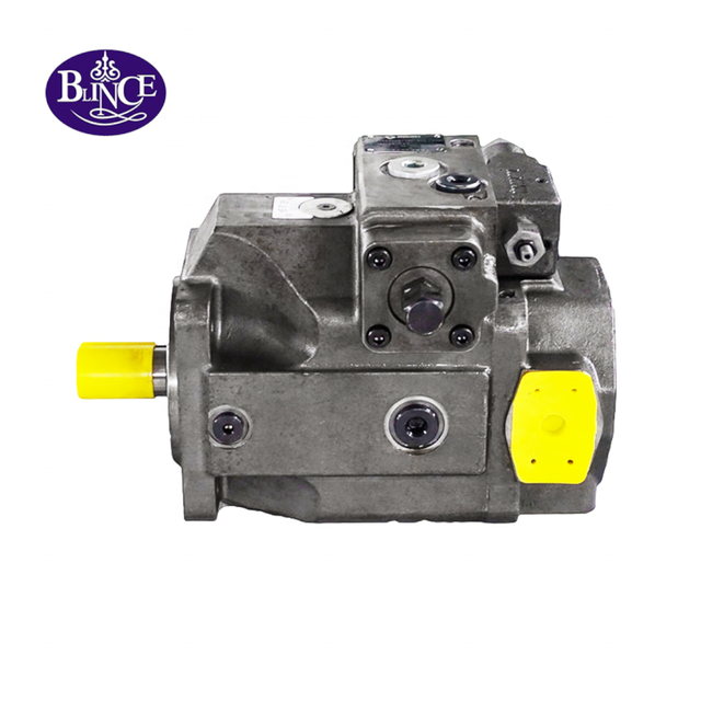
A hydraulic piston pump can fail quietly before it fails expensively.
The first sign may not be a broken pump. It may be oil around the shaft seal. It may be a pump housing that runs hotter than the tank. It may be a case drain hose that jumps when the machine loads. On a test bench the pump may still build pressure, so the first argument starts: seal quality, pump quality, dirty oil, wrong rotation, relief setting, or maybe the operator pushed the machine too hard.
Sometimes the pump is worn. Sometimes the pump was never given a fair place to work.
This guide looks at one detail that is easy to overlook during hydraulic pump replacement: the case drain path. In piston pumps, the oil that leaks inside the housing is doing useful work while it leaves. It carries heat away from the rotating group and gives the case a controlled escape route. When that route is pinched, shared with a busy return, or simply too small, the shaft seal may be the first part to complain even though the real fault sits outside the pump.
For background on the internal layout, the axial piston pump reference is useful: pistons, a cylinder block, a valve plate, and a swashplate all have to work across tight clearances. In the field, those small clearances are the reason a drain hose, oil temperature, and cleanliness issue can turn into a pump complaint instead of staying a small plumbing detail.
Why Trust This Guide
Blince supplies hydraulic pumps along with the motors, valves, cylinders, hoses, fittings, coolers, gauges, and accessories that sit around them. That wider view matters here because a piston pump is often the part that leaks first, while the condition that pushed it there may be in the return, suction, cooling, or control side.
A shaft seal may leak because the pump is worn. It may also leak because the drain line is tied into a high-pressure return, the oil cooler is restricted, a quick coupler is undersized, the reservoir is overfilled, or a pressure spike is forcing internal leakage faster than the drain can carry it away. The article Hydraulic Pressure Gauge Placement Guide is relevant here because one normal outlet pressure reading can hide a case pressure problem.
The article is meant for repair shops, buyers, maintenance teams, and equipment builders who need a practical review before approving a pump repair or replacement. A test bench still has its place. The field job, though, is usually messier: read the failure story, look at the drain line, compare the pressure points you can reach, inspect the inlet side, and only then decide whether the answer is a replacement pump, a hose correction, a tank cleanup, or a larger system review.
Start With the Leak Story, Not the Pump Model
Before choosing a replacement hydraulic piston pump, put the failure into shop language first.
Was the seal wet as soon as the pump started, or did it stay dry until the oil warmed? Did the noise show up on the first cold start, or only when the machine loaded? Was the drain hose pulsing, foaming, or getting hot sooner than the main return? Also note what changed before the trouble began: a hose, pump size, oil cooler, valve section, tank cleaning, or oil grade.
Those details usually separate a pump fault from an installation fault or a circuit fault. The model number still matters, but it is not enough by itself. Without drain routing, inlet condition, oil temperature, and pressure readings, a hydraulic pump repair can become a repeat repair with a cleaner invoice and the same cause.
On a work order, a plain sentence is often more useful than a long parts list:
The pump stays dry at start-up, then the shaft seal weeps after roughly twenty minutes under load; the case drain hose feels hot before the main return line does.
That note gives the supplier a direction. It does not prove the cause, but it points toward case pressure, drain restriction, internal wear, oil temperature, or return layout before the discussion collapses into "quote the same pump."
What a Case Drain Actually Does in a Piston Pump
A piston pump is not dry inside. A small amount of oil is always passing through the clearances around the rotating group, valve plate, slipper pads, pistons, control pistons, and bearings. When the pump is healthy and the drain is open, that oil removes heat and keeps internal parts lubricated before it leaves through the case drain port.
This is not the same as an external oil leak. A controlled case drain is part of the pump's working condition. The trouble begins when drain flow becomes too high, drain pressure becomes too high, or the drain path sends oil somewhere it should not go.
Drain observation
What it may mean
First field check
Low drain flow and hot housing
Drain line may be blocked or case may not be filling correctly
Check drain hose, fitting bore, and pump start-up procedure
High drain flow but low drain pressure
Pump internal leakage may be high
Compare flow after warm-up and under load
Normal drain flow but high drain pressure
Drain path may be restricted
Measure case pressure at the pump, not only at the tank
Foamy drain oil
Air may be entering suction side or oil may be aerated
Inspect suction hose, oil level, breather, and return flow
Drain oil full of metal
Internal wear may already be moving through the system
Inspect filter, tank bottom, and downstream components
Use the table as a starting point, not a verdict. Case drain data becomes useful only when it is connected to temperature, pump load, oil condition, and machine behavior.
Case Drain Pressure Is Not the Same as Case Drain Flow
Many wrong diagnoses begin with the sentence: "oil is coming out of the drain, so the drain is fine."
Flow and pressure are different checks. A drain line can pass oil and still create damaging back pressure. A small fitting, long hose, high return manifold, cold oil, plugged cooler, clogged filter, or shared return path can make the pump housing run at a pressure the shaft seal was not meant to hold.
A piston pump shaft seal should not be treated as a pressure-control device. It keeps oil inside the housing only under the case condition the pump was designed to see. When the drain line pushes back, the seal can weep even though the rotating group has not failed yet. Replace the seal and leave that drain path untouched, and the next seal often has a shorter life than the first one.
For a practical test, put a liquid-filled pressure gauge near the case drain port, as close as the machine safely allows. Run the function that creates the complaint, not a gentle idle test. Compare cold start, warm idle, no-load motion, and full-load operation. A tank-end reading can look harmless while the pump end is fighting a hose, fitting, or manifold restriction.
Where the Drain Line Should Return
A good drain path is usually boring: low pressure, unrestricted, and returning to the reservoir in the manner the pump and machine design allow. It should not whip oil into the tank, pull air, or climb through a route that traps oil and heat. The exact port location varies, but the working rule is the same: do not let the drain line become a hidden pressure line.
Be careful with shared return manifolds. A line that handles cylinder return flow, motor return flow, cooler flow, and valve tank flow may be quiet at idle and busy ten seconds later. If the case drain is tied into that point, measure pressure there during real work, especially when several functions move at the same time.
The drain hose also deserves the same inspection as any other hydraulic line. Look at length, bend radius, clamp points, rub marks, and fitting bore. A tidy hose route can still be wrong if it climbs high, traps air, or uses a reducer that nobody noticed during installation. If the drain line passes through a quick coupler, check the coupler style and internal passage; the guide on hydraulic quick coupler pressure drop explains why outside size and internal flow path are not the same thing.
During replacement work, do not call the drain hose "just a leakage tube" and leave it out of the review. The hydraulic hoses and fittings around a pump can decide whether the new unit starts with a clean low-pressure drain or with a restriction already built into the repair.
Shaft Seal Leakage: When the Seal Is Only the Messenger
A leaking pump shaft seal is visible. That is why it gets blamed quickly.
The seal can be worn, cut, hardened, installed incorrectly, or damaged by shaft surface wear. Those are real failures. But on piston pumps, a shaft seal leak is also a common symptom of excessive case pressure, poor drain routing, hot oil, bearing movement, misalignment, contamination, or pressure spikes.
Before replacing the seal, inspect the shaft surface. A polished groove, rust mark, spiral scratch, or fretting band near the lip area tells a different story from a clean shaft with a seal pushed outward. If the pump is driven through a coupling, also check alignment and pipe stress. The article on hydraulic pump coupling alignment is useful here because a moving pump body can damage both the coupling and the seal.
If the pump seal leaks only when oil is hot, do not stop at the seal. Hot oil is thinner, leakage increases, and the drain line may see more flow. A drain path that barely works cold can become too restrictive after the pump reaches real operating temperature.
When heat and leakage appear together, check whether the system is losing power through relief flow, valve restriction, or return pressure. Blince's article on normal pressure but lack of power is a useful diagnostic bridge when the pump outlet gauge looks acceptable.
High Case Drain Flow: Wear, Heat, or Normal Leakage?
A piston pump always has some internal leakage. The question is whether the amount is normal for that pump, pressure, speed, oil viscosity, and temperature.
High case drain flow often sends the repair toward the rotating group, valve plate, piston shoes, barrel face, control piston, or bearing area. That may be correct. But hot, thin oil can make the same pump look much worse than it did during a cold ten-minute test, so record the temperature before treating the flow number as a verdict.
Do not compare drain flow without recording the condition. A useful note includes pump speed, outlet pressure, oil temperature, oil grade, control setting, and function being used. If the pump is variable displacement, also record whether it is at standby, partial stroke, or full stroke.
If the drain flow is high but case pressure remains low, the pump may be worn internally. If drain flow is not especially high but case pressure rises, the drain path may be the main suspect. These two faults can look similar from outside the machine but lead to different repair decisions.
Low or Missing Drain Flow Can Be Dangerous Too
Some technicians only worry when drain flow is high. Low or missing drain flow deserves attention as well.
A blocked drain, capped drain port, collapsed hose, plugged fitting, or wrong return route can trap oil and heat in the housing. Start-up adds another risk. Some piston pumps need the case filled before the shaft turns, so after shipping, storage, or a dry installation, confirm the filling procedure before anyone jogs the drive.
A full reservoir does not guarantee a lubricated pump. A closed inlet valve, empty suction hose, dry case, or blocked drain can leave the first few seconds of rotation almost unprotected. The result may not be a loud failure on the spot; it may come back later as noise, heat, metal powder, or rising drain flow.
For machines that have recently received a reservoir repair, suction hose change, or filler cap replacement, also inspect the hydraulic accessories around the tank. A small breather, gauge, cap, or adapter can affect the conditions that the pump sees during start-up.
Inlet Conditions and Cavitation: The Drain May Be Warning You
Case drain complaints often travel with inlet complaints. When the pump cannot receive oil cleanly, cavitation and aeration start marking internal parts and leakage rises. The clues may be ordinary shop clues: foamy drain oil, a sharper pump whine, or a housing that gets hot before the rest of the circuit catches up.
On the inlet side, start with the plain checks: oil level, suction valve position, hose size, suction strainer condition, cold oil viscosity, dry-looking suction fittings that may pull air inward, reservoir turbulence, and whether the tank breather can admit air fast enough. The hydraulic tank breather selection guide is a useful companion when pump noise appears after reservoir or breather work.
Do not keep tightening suction fittings because there is no visible oil leak. A suction leak may pull air inward while leaving the outside dry. If the case drain oil looks milky or foamy, check the suction side before ordering another pump.
Return Back Pressure, Coolers, and Filters
The case drain line may be correct at the pump and still become wrong downstream.
If the drain returns into a shared line, that line may see back pressure from return filters, oil coolers, valve blocks, long hoses, or undersized fittings. This is common when a machine has been modified: a cooler is added, a return filter is upgraded, a manifold is rearranged, or a new attachment increases flow.
Hydraulic coolers and filters are helpful only when the circuit can carry the required flow without excessive pressure drop. If the case drain joins a restricted return path, the pump can leak even though the cooler and filter look like improvements. The article Hydraulic Oil Cooler Sizing Guide explains this trap from the cooling side.
If a cooler has been added or replaced, check whether the pump drain is isolated from the cooler pressure drop. Blince supplies hydraulic heat exchangers, but the cooler still has to be placed where it removes heat without raising case pressure.
For pump case drains, the key habit is simple: measure pressure where the pump feels it. If the reading rises only when the oil is cold, viscosity and filter bypass behavior may matter. If it rises only when the machine uses a second function, the shared return path deserves a closer look.
Control Pressure and Variable Pump Behavior
Variable displacement piston pumps add another layer. The pump may have a pressure compensator, load-sensing control, power control, pilot control, or electronic proportional control. A case drain complaint can be mixed with a control complaint.
If the pump stays on stroke when it should destroke, heat builds before anyone has done much useful work. A high standby setting wastes power at idle. A load-sense line that is trapped, leaking, restricted, or connected to the wrong point can make the pump hunt, chatter, or hold pressure even while the operator believes the circuit is at rest.
Before condemning the rotating group, check whether the pump control is receiving the correct signal. A pressure-compensated pump that never compensates can make the drain flow look worse than it would under normal control. A load-sensing pump with a blocked signal line can make the machine feel weak while the pump still appears mechanically capable.
When the symptom involves multiple functions, compare pump outlet pressure, load-sense pressure, case pressure, return pressure, and oil temperature during the same movement. The article Why Hydraulic Systems Show Normal Pressure But Lack Power is relevant because pump control problems often hide behind one acceptable gauge reading.
If the pump control depends on downstream valve behavior, review the hydraulic directional control valve selection guide. A spool center, relief setting, or pilot path can keep a pump loaded when the operator thinks the circuit is neutral.
Gear Pump, Vane Pump, and Piston Pump Drain Differences
Not every hydraulic pump uses case drain plumbing in the same way.
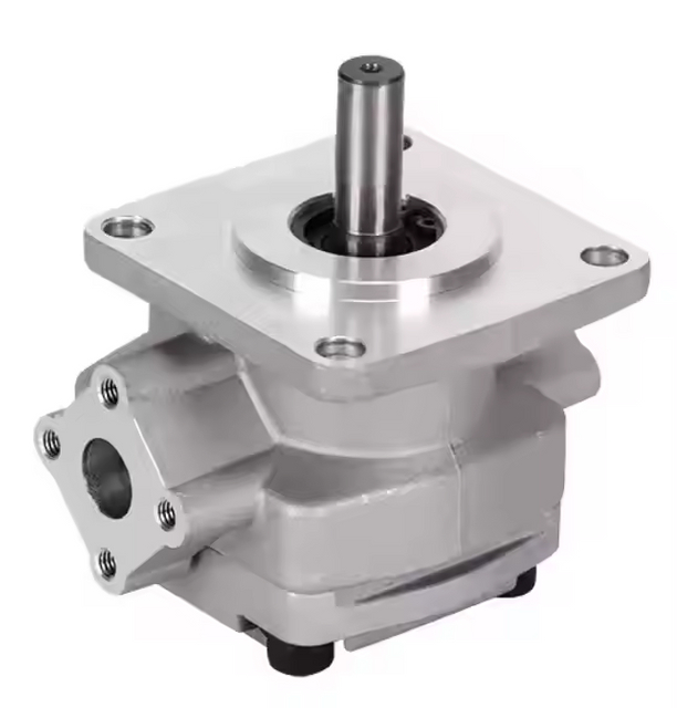
Many gear pumps are simpler and may return internal leakage inside the pump body without a separate external drain port. Vane pumps may have different leakage and control requirements depending on design. Piston pumps, especially axial piston pumps and variable displacement pumps, are less forgiving because the rotating group, control system, and housing leakage are more sensitive to temperature, pressure, and contamination.
Pump type
Typical field strength
Drain-related caution
Gear pump
Simple, robust, cost-effective
Inlet starvation and shaft seal pressure can still destroy it
Vane pump
Smooth flow, good for moderate pressure
Needs clean oil and stable inlet conditions
Axial piston pump
High pressure, variable flow, efficient control
Case drain pressure, filling, control signals, and filtration matter
Radial piston pump
High pressure and strong load capability
Drain and lubrication details depend heavily on design
This is why a replacement decision should not be made from displacement and mounting alone. The article Types of Hydraulic Pumps is a good supporting page for buyers who are still comparing gear, vane, and piston pump options.
How to Measure Case Pressure Without Creating a New Problem
A gauge test should be useful, not dangerous.
Use a gauge with a suitable low pressure range for the expected case pressure, not only a high-pressure system gauge. A 400 bar gauge can move slightly and still hide the difference between a healthy drain and a risky drain. Use proper test fittings, keep hoses clear of rotating parts, and do not loosen drain fittings under pressure.
For repeated troubleshooting, quick test points and readable gauges are worth planning into the machine. The hydraulic pressure gauge is useful only when it is installed where the failure actually changes the reading.
Measure the case pressure at the pump if possible. Then compare with the pressure near the tank or return manifold. If the pump-end reading is much higher, the restriction is between those two points. If both readings rise together, the return destination or downstream path may be the problem.
Record readings at four moments:
Test moment
Why it matters
Cold start
Shows viscosity, suction, and filter restriction problems
Warm idle
Shows baseline drain pressure and control behavior
Main function under load
Shows case pressure during real work
Second function added
Shows shared return and load-sense interaction
The numbers do not need to be fancy. They need to be taken under the same condition that creates the complaint.
Contamination: The Pump May Be the First Victim, Not the Only Victim
A failed piston pump can send debris through the system. A dirty system can also destroy the next piston pump. Both directions happen in the field.
When the old pump has failed internally, the replacement is not going into a clean world by default. Check the tank, filters, suction screen, return line, cooler, hoses, valve block, and actuators before calling the oil path safe. Metal can hide in a hose or manifold and come back after the new pump is already running; the hydraulic contamination control guide is a useful companion when the history includes metal powder, sticky valves, repeated seal failure, or early filter plugging.
Oil cleanliness matters more for piston pumps than many buyers expect. The clearances are small, sliding surfaces carry high load, and the control system may include small orifices and pilot passages. The pump may be the expensive part on the invoice, but the dirt may have entered through a filler cap, breather, hose replacement, opened fitting, or sludge that was already sitting in the reservoir.
Equipment-Specific Checks
Excavators and Construction Machinery
Excavator piston pumps live in a hard neighborhood: high pressure, load-sensing control, pilot circuits, and frequent multi-function movement. The first complaint may not mention the drain at all. It may show up as a slow boom, weak travel, hot oil, pump noise, or another shaft seal leak.
Check whether the complaint appears during one function or several. If several functions feel weak together, pump control, suction conditions, main relief behavior, and case pressure deserve attention. If only one function is weak, a hydraulic valve, cylinder, motor, hose, or circuit branch may be the better suspect.
For excavator travel or swing complaints, do not ignore the actuator side. Blince's article on excavator hydraulic system faults is useful when pump output, valve control, and final drive symptoms overlap.
Industrial Hydraulic Power Units
Industrial power units often look calm because the pressure is steady and the machine stays indoors. That calm can be misleading. High standby pressure, a hot reservoir, a restricted drain, poor coupling alignment, or an undersized cooler can shorten piston pump life without creating a dramatic event.
For power units, note motor speed, coupling type, pump rotation, reservoir level, oil temperature trend, cooler condition, and whether the pump destrokes at standby. A variable pump that stays loaded at idle can produce heat long before anyone sees oil on the floor.
If the pump is driven by an electric motor, include voltage, current, speed stability, and coupling condition in the review. A full hydraulic system check often shows that the pump is reacting to a drive, base, or piping condition rather than failing alone.
Agricultural and Forestry Equipment
Agricultural machines may sit for weeks and then work long days in dust, heat, vibration, and changing oil quality. A piston pump drain line can be hit by mud, bent during service, or quietly tied into a return path that was never sized for the new attachment added last season.
Before replacing a pump on this type of machine, check the suction hose, tank breather, filler practice, oil grade, case drain hose routing, quick couplers, and return filter. A small field change can be enough to make the next pump fail early.
Agricultural failures often involve hose handling and seasonal contamination. The Hydraulic Tubing Selection Guide is useful when a replacement hose fits the thread but changes inlet restriction or return pressure.
Mobile Attachments and Auxiliary Circuits
Attachments can change the machine more than the base unit owner expects. A new mulcher, sweeper, drill, or hydraulic winch can raise return flow, heat, pressure spikes, and tank turbulence. If the pump complaint started after the attachment change, the attachment plumbing belongs in the inspection.
The answer may be a different valve setting, a larger return line, lower back pressure, more cooling, or a dedicated drain path. When the symptoms include slow attachment speed and heat, the hydraulic pump motor matching guide can help connect pump flow, motor demand, pressure drop, and oil temperature.
When the attachment uses a motor, compare pump flow with the motor displacement and return pressure. A correct hydraulic motor can still run hot if the pump, valve, quick coupler, and drain path are mismatched.
Practical Checklist Before Ordering a Replacement Pump
Before ordering a hydraulic piston pump, pump seal kit, or pump repair, run through the checklist while the machine history is still fresh.
Question
Why it matters
What failed first: seal, noise, heat, weak flow, or metal debris?
The first symptom points to the failure path
Is the pump case filled before start-up?
Dry start can damage internal surfaces
Where does the drain line return?
High return pressure can push oil past the seal
What is case pressure at the pump during the complaint?
Tank-end pressure may hide hose restriction
Is case drain flow high after warm-up?
High flow may indicate internal wear
Is the drain oil foamy?
Air entry or aeration may be present
What is inlet condition during cold start?
Cavitation may begin before pressure work starts
Is the oil cooler or return filter restrictive?
Back pressure may rise only under real flow
Has the machine been modified recently?
New hoses, couplers, valves, or attachments change conditions
Is there metal in the old pump, tank, or filter?
A new pump may be contaminated quickly
Does the pump destroke or stay loaded at standby?
Control faults create heat and leakage
Are pump speed and rotation correct?
Wrong rotation or overspeed can destroy the pump quickly
If several answers are unknown, selection can still begin, but the quote should be called preliminary. The fewer unknowns, the lower the chance of buying a pump that fits the flange but fails in the circuit.
Common Mistakes in Piston Pump Case Drain Diagnosis
Mistake 1: Replacing the Shaft Seal Without Measuring Case Pressure
A seal can fail because it is worn. It can also fail because the housing pressure is too high. If the drain restriction remains, the new seal may leak again after the first hot cycle.
Mistake 2: Returning the Drain Into a Busy Return Manifold
A return manifold may be low pressure during idle and high pressure during combined functions. If the case drain joins that path, the pump may see pressure only when the machine is working hardest.
Mistake 3: Using a High-Range Gauge for a Low-Pressure Drain Test
A normal system pressure gauge may not show small but important differences in case pressure. Use a range that lets the needle movement mean something.
Mistake 4: Ignoring Cold Oil
Cold oil raises pressure drop through hoses, filters, coolers, and fittings. A drain line that works after warm-up may still hurt the pump during cold start.
Mistake 5: Treating High Drain Flow and High Drain Pressure as the Same Fault
High drain flow often points toward pump wear or hot thin oil. High drain pressure often points toward restriction. They may occur together, but they should be separated during diagnosis.
Mistake 6: Installing a New Pump Into Oil That Still Carries the Old Failure
If the previous pump failed internally, debris can remain in the reservoir, filters, cooler, valves, and hoses. A clean-looking replacement pump may be damaged by the same oil path that damaged the first one.
Mistake 7: Forgetting the Control System
Variable piston pumps respond to pressure, load-sense, pilot, or electronic signals. A control fault can make the pump run hot, stay on stroke, or hunt under load.
Mistake 8: Blaming the Pump for an Inlet Problem
Pump cavitation can begin before the pump builds useful pressure. Check oil level, suction restriction, air entry, viscosity, breather flow, and reservoir layout before deciding the pump is defective.
A Better Quote Request Format
Instead of writing "quote same pump," send a short technical note:
The machine uses an axial piston pump on an industrial power unit. The shaft seal stays dry at start-up, then leaks after about 40 minutes under load. Pump outlet pressure is 180 bar during the main function. Case pressure measured at the pump is 2.8 bar when warm and rises when the cooler fan starts. The drain returns through a shared return manifold. Oil temperature reaches 68°C. Photos of the drain hose, pump nameplate, coupling, and filter element are attached.
That message gives a supplier something solid to work with: pump type, failure timing, pressure condition, drain behavior, temperature, and a likely restriction point.
For a mobile machine, add the drive arrangement as well: belt drive, PTO, engine mount, or electric motor. Then include pump rotation, inlet hose size, reservoir position, case drain routing, and any recent attachment or return-filter change.
If the pump problem follows a cylinder rebuild or load-holding change, include actuator information too. Blince's hydraulic cylinder drift guide shows why leakage, pressure trapping, and valve behavior can be mistaken for pump weakness.
FAQ
What is the case drain on a hydraulic piston pump?
The case drain is the path that lets internal leakage leave the pump housing. In many piston pumps, that leakage helps cool and lubricate internal parts before returning to the reservoir. The drain must not be restricted or tied into a high-pressure return path.
Why does a hydraulic piston pump shaft seal leak?
Common causes include high case pressure, blocked or undersized drain line, hot oil, worn shaft surface, bearing movement, misalignment, contamination, wrong installation, or internal pump wear. Do not replace the seal without checking drain pressure.
Is high case drain flow always a bad pump?
Not always. High drain flow can indicate internal wear, but it can also rise with hot oil, low viscosity, high pressure, or control behavior. Record oil temperature, outlet pressure, pump speed, and function before deciding.
Can a case drain line be connected to the main return line?
Sometimes it is done, but it is risky unless return pressure is known under real operation. The drain should return through a low-pressure path that does not see high back pressure from filters, coolers, valve blocks, or other actuator return flow.
What happens if the case drain line is blocked?
Blocked drain flow can raise housing pressure, overheat internal parts, push oil past the shaft seal, damage bearings, and starve internal lubrication. Some pumps can fail quickly if the case is not filled and drained correctly.
How do I check hydraulic pump case drain pressure?
Install a suitable low-range gauge near the pump case drain port and run the machine under the same condition that creates the complaint. Compare cold start, warm idle, loaded work, and combined functions.
Why does the pump leak only after the oil gets hot?
Hot oil becomes thinner. Internal leakage can increase, and the drain line must carry more oil. If the drain path is marginal, case pressure may rise only after warm-up.
Should I flush the system before installing a new piston pump?
If the old pump failed internally or metal debris is found, inspect and clean the reservoir, filters, cooler, hoses, valve block, and return path before installing a replacement. Otherwise the new pump may ingest old contamination.
Final Takeaway
Hydraulic piston pump case drain diagnosis should begin with the failure pattern, not the seal kit. A leaking shaft seal, hot housing, foamy drain oil, noisy start-up, or repeat pump failure is asking a practical question:
Where is the leakage going, and what pressure is the pump housing actually seeing?
If the drain path is clean, low pressure, correctly routed, and matched to the pump, then high drain flow may point toward internal wear. If the drain path is restricted, shared, kinked, or affected by cold oil, cooler pressure drop, or return back pressure, the pump may be blamed for a circuit problem.
For hydraulic piston pump replacement, case drain review, shaft seal leakage diagnosis, hydraulic pump repair, or a broader system check, send Blince the pump nameplate, photos of the pump and drain line, inlet hose size, case pressure readings, outlet pressure readings, oil temperature trend, filter condition, and the first symptom that appeared. Blince can help compare the hydraulic pump, hose, valve, cooler, gauge, and reservoir conditions before the next replacement repeats the same failure.
This article is a general engineering guide. Final component selection should be based on machine drawings, measured hydraulic data, working conditions, safety requirements, and confirmation from a qualified hydraulic engineer or supplier.
Blince Hydraulic Team
Blince Hydraulic is an industry-leading company dedicated to precision-engineered fluid power manufacturing and custom hydraulic solutions. Backed by decades of deep field expertise in industrial machinery and thousands of successful global deployments, our engineering team focuses entirely on high-performance hydraulic component manufacturing, including specialized orbital motors, high-pressure travel drives motor, and robust directional control valves. Our production infrastructure utilizes state-of-the-art multi-axis CNC machining systems and is fully ISO 9001 certified to guarantee repeatable volumetric accuracy across every single manufacturing run.
We deliver fast, highly dependable, and cost-efficient hydraulic solutions to heavy industry distributors, machinery OEMs, and maintenance crews across more than 150 countries. Whether your active project calls for a small-volume batch of customized shaft profiles or a large-scale production run of severe-duty cast iron gear pump, we configure our flexible production schedules to meet your target lead times with total pricing predictability. Partnering with Blince means securing maximum system efficiency, elite material quality, and uncompromised fluid power professionalism.
To learn more about our complete product lineup, visit our official website: www.blince.com.