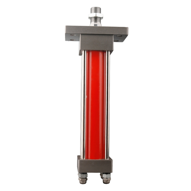
A replacement cylinder can fit the pins and still leave the machine weak. The opposite error is just as common: a buyer increases the bore “for safety,” then discovers that the old pump cannot fill it fast enough. Cycle time rises, the valve sees more return flow, and the larger body no longer clears the frame.
The bore calculation itself is short. Most sizing errors begin earlier, when force, pressure or effective area is chosen. A load on a lever is not the same as force at the cylinder pin. Relief-valve setting is not necessarily pressure at the cap end. Retraction does not use the full piston area. Rod-side backpressure can subtract meaningful extension force.
Short answer
For a preliminary hydraulic cylinder bore size, calculate the cylinder force required at the worst linkage position, divide that force by the usable pressure at the cylinder, then convert the required piston area to a diameter. Round up to a standard bore and check the result again for rod-side backpressure, friction, pull force, speed, oil volume, return flow, rod buckling and mounting geometry.
The basic extension relationship is F = p × A, but a purchase decision should not stop there. A bore that makes enough theoretical force can still be too slow, physically too large, paired with an undersized rod, or unsuitable for the load-holding circuit.
Key takeaways
Bore sets piston area. Pressure acting on that area creates theoretical force.
The rod removes effective area on retraction, so pull force is lower than push force in a conventional single-rod cylinder.
A larger bore raises force at a given pressure but reduces speed at a fixed pump flow.
Pressure at the cylinder ports under load matters more than a pump catalog maximum or an unloaded gauge reading.
Linkage angle can multiply the cylinder force required even when the external load has not changed.
The result is a preliminary size, not approval of the rod, tube, mount, pins, cushions, seals or load-holding system.
Start with the force at the cylinder, not the payload label
Suppose a platform carries a 20 kN load. It is tempting to enter 20 kN into a bore calculator. That only works when the cylinder acts directly along the load path with no lever, angle or acceleration effect. Most booms, dump bodies, clamps and linkages do not.
For a simple pivoting mechanism, compare moments about the pivot:
Required cylinder force = load moment / effective cylinder moment arm
If the load produces 20 kN × 0.8 m = 16 kN·m, and the cylinder pin is 0.35 m from the pivot at a 30° working angle, its effective moment arm is:
0.35 m × sin(30°) = 0.175 m
The ideal cylinder force is therefore:
16 kN·m / 0.175 m = 91.4 kN
At 60°, the effective arm becomes 0.35 × sin(60°) = 0.303 m, and the same external load needs only about 52.8 kN. This is why a dump body may be hardest to start near the bottom even though the payload is unchanged. The smallest effective lever arm, highest expected load, friction, acceleration and shock condition should control the sizing input.
This simplified example is Calculated. It does not include the mass of the structure, changing center of gravity, joint friction, dynamic impact or frame deflection. Obtain those inputs from the machine drawing or a qualified mechanical analysis.
The areas that matter
For a conventional double-acting, single-rod cylinder:
Cap-end piston area A1 = πD⊃2; / 4
Rod area Ar = πd⊃2; / 4
Rod-end annulus area A2 = π(D⊃2; - d⊃2;) / 4
where D is bore diameter and d is rod diameter.
Ideal extension force uses the full cap-end area. Ideal retraction force uses the smaller annulus area. Parker publishes the metric relationship F(kN) = P(bar) × A(mm²) / 10,000 in its hydraulic cylinder engineering catalog. Danfoss presents the same pressure-area principle along with cylinder speed and oil-consumption relationships in its Tips on Hydraulics reference.
These formulas calculate theoretical output from the stated inputs. Seal friction, guide friction, piping losses, valve pressure drop, rod-side backpressure and pressure transients change the force available at the machine.
Use pressure at the cylinder, not merely the relief setting
A system relief set to 140 bar does not prove that 140 bar reaches the cap end while the machine moves. Pump wear, engine speed, a restrictive directional valve, undersized hose, clogged filter or pressure-compensated control can reduce the pressure-flow combination available at the actuator. A gauge installed upstream of a restrictive valve can also show something different from a gauge at the cylinder port.
Backpressure matters as well. During extension, pressure on the rod side acts against motion across the annulus area. A practical preliminary expression is:
Fnet = (pcap × A1 - prod × A2) × η
η is an assumed mechanical factor used for comparison. It is not a universal efficiency constant. When verified friction or manufacturer load-rate guidance is unavailable, do not hide uncertainty inside a precise-looking percentage. Run more than one scenario and obtain application review.
Parker's heavy-duty metric cylinder catalog notes that sliding resistance and pressure loss in piping and equipment must be considered. It also publishes load-rate guidance for that product context. Those percentages are useful evidence that theoretical force is not working force, but they are not a BLINCE specification.
Worked example: compare 63, 80 and 100 mm bores
Assume the linkage analysis has already produced a required design extension force of 50 kN. Pressure measured at the cap-end port during the demanding part of the stroke is 120 bar. Rod-side backpressure is 10 bar. For a preliminary comparison only, use a mechanical factor of 0.90 and a pump flow of 25 L/min.
Candidate bore/rod pairs are 63/35, 80/40 and 100/50 mm. These dimensions appear among the public combinations on the BLINCE HOB double-acting tie-rod cylinder page, but the current project drawing and datasheet must confirm the actual configuration.
For the 80/40 mm candidate:
A1 = π × 80⊃2; / 4 = 5,026.5 mm²
A2 = π × (80⊃2; - 40⊃2;) / 4 = 3,769.9 mm²
Fnet = [(120 bar × 5,026.5 mm²) - (10 bar × 3,769.9 mm²)] / 10,000 × 0.90
Fnet = 50.9 kN
The 80 mm candidate clears the 50 kN example requirement by a small amount under these assumptions. It is not approved until pressure spikes, load uncertainty, rod buckling, mount strength, side load, fatigue and the selected series limits are checked.
Candidate bore/rod
Net extension force at the stated conditions
Ideal extension speed at 25 L/min
Ideal time for 500 mm
Preliminary reading
63/35 mm
31.7 kN
133.7 mm/s
3.74 s
Too little force for 50 kN
80/40 mm
50.9 kN
82.9 mm/s
6.03 s
Force match worth investigating
100/50 mm
79.5 kN
53.1 mm/s
9.42 s
More force, slower at the same flow
This comparison shows the main tradeoff. Moving from 80 to 100 mm raises the example net force by roughly 56%, but extension speed at the same 25 L/min falls from about 83 to 53 mm/s. More bore is not free capacity; it consumes more oil per millimeter of travel.
Convert the chosen bore into a flow and cycle-time check
Cylinder speed is chamber flow divided by effective area:
v = Q / A
With unit conversion, 25 L/min into the 80 mm cap end gives:
A 500 mm stroke would take about 500 / 82.9 = 6.03 seconds ideally. Leakage, valve metering, ramping, pump speed and load variation can make the real time longer.
The cap-end oil volume is:
Vcap = 5,026.5 mm² × 500 mm = 2.513 L
The 80/40 mm annulus volume is 1.885 L. With 25 L/min entering the rod end, ideal retraction speed is about 110.5 mm/s, so the cap end exhausts approximately 33.3 L/min. The return path must accommodate that flow. Selecting a valve and hose for the 25 L/min pump figure alone can create backpressure during retraction.
At 120 bar and 25 L/min, theoretical hydraulic power is:
The electric motor or engine input must be higher after pump, drive and control losses. Bore selection can therefore change cycle time and power demand without changing the load.
Push force and pull force are different decisions
On extension, the cap-end pressure acts on the full bore. On retraction, the rod occupies part of the piston, leaving the annulus. With the 80/40 mm example, the annulus is about 75% of the cap area. At equal pressure and with no backpressure, theoretical pull force and oil volume are therefore about 75% of their extension counterparts, while retract speed at equal input flow is about 1/0.75, or 1.33 times the extension speed.
That area ratio also affects pressure and flow behavior in regenerative or trapped-oil conditions. Do not increase rod diameter only to improve buckling strength without recalculating pull force, retract speed, return flow and any pressure intensification path.
A bore chart is a starting point, not the order code
A hydraulic cylinder bore size chart usually assumes a stated pressure and ideal piston area. It cannot see the machine linkage, pressure loss, backpressure, side load, rod length, mounting condition, duty cycle or temperature. Use it to shortlist a bore, then move to the selected series drawing.
BLINCE's public HOB page describes a 40–250 mm bore range, a 0.3–14 MPa pressure range and strokes up to 5000 mm. The page also lists flange, rear-ear and foot examples. These are Published family boundaries, not confirmation that every maximum can be combined in one cylinder.
The lighter MOB 7 MPa family lists bore values from 30 to 125 mm and several rod sizes. HOB may suit a higher-pressure or heavier tie-rod requirement; MOB may suit a lighter industrial duty. An HSG cylinder route or a custom design may fit machinery-specific geometry. Bore calculation narrows the search, but pressure, rod, mount, envelope and duty decide the family.
Tradeoff 1: larger bore or higher pressure?
A larger bore can meet force at lower pressure. That can reduce the pressure demanded from the pump and some valves, but the larger cylinder needs more oil, more space and often a larger rod, port and structure. Cycle speed falls if pump flow stays fixed.
Raising working pressure can keep the cylinder compact and reduce oil volume for a given force. The cost is higher stress and stricter requirements for the pump, valve, hoses, fittings, seals, tube, end caps and mount. A relief adjustment is not a substitute for verifying every component rating and the machine risk assessment.
Choose between bore and pressure at the system level. If the pump cannot sustain the pressure at the required flow, the theoretical compact solution will not work. If the frame cannot accept a 100 mm bore body, the low-pressure solution will not fit.
Tradeoff 2: force margin or cycle time?
Rounding up one standard bore is normal after a calculated minimum, provided the rest of the system is checked. Rounding up repeatedly “to be safe” can produce a slow actuator, higher return flow and more stored hydraulic energy. It can also make low-speed control harder if the valve must meter a very small fraction of available flow.
A smaller bore gives more speed per liter and may fit a compact envelope, but it requires higher pressure for the same load and leaves less allowance for friction, backpressure or load variation. The appropriate margin depends on verified loads, dynamics, control behavior and the governing design standard—not a generic multiplier copied from a web calculator.
Equipment-specific checks after the bore calculation
Press or clamp
Use the force at the tooling, not only the cylinder rating. Account for platen guides, die contact, off-center work, approach speed, pressing speed and return speed. A large bore may provide force but demand a two-stage pump or fast-approach circuit to keep cycle time reasonable. The machine guides should carry side force; the rod should not guide the platen.
Dump body, boom or tilting platform
Calculate the worst linkage position across the whole stroke. The startup angle often controls. Check changing center of gravity, shock, over-center geometry and the load-holding circuit. The recent BLINCE guide to hydraulic cylinder mounting types explains why a correct bore does not correct a clevis, trunnion, flange or foot mount that sends force through the wrong path.
Injection molding or industrial automation
Separate rapid traverse from the high-force portion of the cycle. A cylinder sized only for peak clamp force can waste flow during approach. Confirm repeatability, cushioning, valve response, oil temperature, seals, sensors and whether a differential or regenerative circuit changes the area used.
Mobile and agricultural machinery
Measure pressure and engine speed during the real duty. Pump flow may change with engine rpm, and multiple functions may share flow. Mud, corrosion, impact, pin wear and hose routing can dominate service life even when the force calculation is correct.
Checks the bore formula does not perform
Rod buckling and tensile stress
A long rod pushing in compression can buckle before the theoretical piston force is useful. Rod diameter, unsupported length, end restraint, extension, material and side load control the buckling calculation. Pull duty instead places the rod in tension, but the thread, eye, clevis and mount still need a strength and fatigue check.
Mounts, pins and frame stiffness
The cylinder should transmit axial force. A flexible bracket, worn pin or offset foot mount can bend the rod or concentrate load even when the bore is correct. The BLINCE installation and alignment guide covers pin fit, contamination control, hose routing and low-pressure commissioning.
Cushioning and end-of-stroke energy
Force sizing is static unless acceleration and deceleration are added. A heavy mass moving quickly can exceed the cushion's energy capacity near the end of stroke. Confirm moving mass, velocity, orientation, external deceleration, cushion length, backpressure and cycle rate with the cylinder supplier.
Load holding and hose failure
A cylinder bore does not hold a suspended load by itself. Leakage through the directional valve, hose failure, line rupture, seal leakage or an inappropriate load-control valve can allow movement. Safety-critical lifting may require mechanical support, rated load-holding valves, hose-burst protection, redundancy and jurisdiction-specific compliance.
Heat, contamination and seals
Larger bore does not repair dirty oil, a restrictive valve or an overheated system. If the complaint is drift rather than inadequate force, use a cylinder drift troubleshooting path before buying a larger replacement.
Common bore-sizing mistakes
Using payload weight as cylinder force
The linkage may amplify the required force several times near an unfavorable angle. Calculate moments throughout the stroke and include the structure's weight.
Using relief pressure as working pressure
Measure pressure at the relevant cylinder ports while the function performs its worst duty. Record pump speed and flow conditions at the same time.
Ignoring rod-side backpressure
Return-line restriction subtracts extension force and can create heat. Include the measured rod-side pressure and annulus area in the net-force check.
Forgetting pull force
A single-rod cylinder retracts on a smaller area. A bore/rod pair that pushes adequately may not pull the load or release a clamp as required.
Upsizing bore without checking flow
Oil volume increases with the square of diameter. Recalculate extension speed, retract speed, chamber volume, valve flow and the peak return flow.
Treating efficiency as a universal number
An assumed 90% in a worked example is not a product guarantee. Real friction and losses depend on seals, pressure, speed, temperature, side load and circuit restriction.
Selecting bore before rod and mounting checks
Parker's engineering guidance explicitly connects bore selection with rod sizing. A long compression stroke, side load or unsuitable mount can invalidate a force-only result.
Ordering from bore and stroke alone
Two 80 × 500 mm cylinders can differ in rod diameter, closed length, mount centers, pin dimensions, ports, cushions, seals, sensors and pressure rating. Match the full drawing and duty.
Who should not order a cylinder from this calculation alone?
Do not release a purchase from this web calculation alone if the cylinder lifts people, supports a suspended load, works in a press with injury risk, sees unknown shock loads, pushes on a long extended rod, operates in a multi-plane linkage, or replaces a part after repeated rod/seal/mount failure.
Also stop if pressure at the cylinder is unknown, the original drawing is missing, the frame is cracked or bent, pin holes are elongated, the load path cannot be defined, or a larger bore would require raising the relief setting. Those conditions need machine-level engineering and a verified product datasheet.
Data to send before requesting a quote
Provide values, units and the source of each value—measured, drawing-derived or estimated.
Machine type, function and quantity.
Load magnitude, direction, center of gravity and linkage drawing at retracted, mid-stroke and extended positions.
Required push and pull force, including the calculation or assumptions.
Normal pressure, maximum pressure, relief setting and pressure measured at both cylinder ports under load.
Pump flow at the real drive speed and desired extend/retract times.
Bore, rod diameter and stroke of the existing cylinder, if applicable.
Retracted and extended pin-center or mounting-face dimensions.
Mount style, pin/clevis/trunnion/flange/foot dimensions and rod-end details.
Port thread, size, orientation, hose ID and valve model/flow rating.
Cycle rate, dwell time, annual cycles, shock and cushioning requirement.
Fluid, viscosity, temperature range, contamination control and environment.
Load-holding valves, pilot checks, counterbalance valves, sensors or integrated blocks.
Original nameplate, clear photos and dimensional drawing.
Applicable machine standard, safety requirement and inspection procedure.
BLINCE can use this package to compare the public hydraulic cylinder range, identify missing data, and prepare a preliminary HOB, MOB, HSG or custom route. Final suitability remains subject to the confirmed model code, drawing, test requirements and application review.
Frequently asked questions
How do I calculate hydraulic cylinder bore size?
Calculate the required force at the cylinder, divide it by usable pressure to obtain piston area, and convert area to diameter with D = √(4A/π). Round up to a standard bore, then recheck net force with backpressure and losses. Finally check speed, return flow, rod, mount and product limits.
What force does an 80 mm bore cylinder produce at 120 bar?
Ideal cap-end force is about 60.3 kN because the 80 mm piston area is 5,026.5 mm². That is not net machine force. In the worked example, 10 bar rod-side backpressure and an assumed 0.90 mechanical factor reduce preliminary net extension force to about 50.9 kN with a 40 mm rod.
Should I use system pressure or relief pressure?
Use pressure available at the cylinder during the worst operating condition. Relief setting is a protection threshold and may not equal working pressure at the piston. Measure both cylinder ports under load when the procedure can be performed safely.
Why is pull force lower than push force?
On retraction, oil acts on the piston area minus the rod area. The resulting annulus is smaller than the full cap-end area, so pull force is lower at equal pressure. The smaller area also makes retraction faster at equal input flow.
Will a larger bore make the cylinder faster?
No, not at the same flow. A larger bore needs more oil for each millimeter of travel, so it moves more slowly unless pump and valve flow increase. The larger exhaust volume may also raise return flow in the opposite direction.
How much safety factor should I use?
There is no universal web value for every machine. Load uncertainty, dynamics, shock, duty, governing standards, consequences of failure and verified component ratings all matter. Document a design load and margin through the machine's engineering process rather than hiding it in an arbitrary bore increase.
Can two cylinders with the same bore and stroke be interchangeable?
Not necessarily. Rod diameter, closed and extended length, mounting dimensions, pin size, ports, cushions, seals, sensors, pressure rating and duty may differ. Functional interchangeability requires the full model code and drawing.
Does bore size determine lifting capacity?
Bore and pressure determine theoretical piston force. Actual lifting capacity also depends on linkage geometry, backpressure, friction, structure, stability, mount, pins, rod strength, load control and safety requirements.
Can I increase pressure instead of bore size?
Only if every pressure-containing and load-carrying part is rated for the new condition and the pump can provide the required pressure at the needed flow. Do not raise a relief setting to compensate for an undersized cylinder without system approval.
What bore sizes does BLINCE publish for HOB cylinders?
The public HOB page states a 40–250 mm family range and lists HOB40 through HOB250 labels. Confirm the current datasheet because a family range does not mean every bore, rod, stroke and mount combination is available or suitable.
Request a cylinder sizing review
Send BLINCE the load and linkage drawing, push/pull force, pressure measured at both ports, pump flow, target cycle times, bore/rod/stroke, mount and pin dimensions, port details, duty cycle, fluid, temperature, environment, photos and quantity. BLINCE can check the preliminary bore against HOB, MOB, HSG or a custom route, flag missing pressure/flow or geometry data, and prepare the model-specific questions required before quotation.
Send the sizing package to BLINCE. Do not release the cylinder for a safety-critical machine until the selected datasheet, machine drawing, load-holding design and applicable safety review are complete.
This article is a general engineering guide. Final component selection should be based on machine drawings, measured hydraulic data, working conditions, safety requirements, and confirmation from a qualified hydraulic engineer or supplier.
Blince Hydraulic Team
Blince Hydraulic is an industry-leading company dedicated to precision-engineered fluid power manufacturing and custom hydraulic solutions. Backed by decades of deep field expertise in industrial machinery and thousands of successful global deployments, our engineering team focuses entirely on high-performance hydraulic component manufacturing, including specialized orbital motors, high-pressure travel drives motor, and robust directional control valves. Our production infrastructure utilizes state-of-the-art multi-axis CNC machining systems and is fully ISO 9001 certified to guarantee repeatable volumetric accuracy across every single manufacturing run.
We deliver fast, highly dependable, and cost-efficient hydraulic solutions to heavy industry distributors, machinery OEMs, and maintenance crews across more than 150 countries. Whether your active project calls for a small-volume batch of customized shaft profiles or a large-scale production run of severe-duty cast iron gear pump, we configure our flexible production schedules to meet your target lead times with total pricing predictability. Partnering with Blince means securing maximum system efficiency, elite material quality, and uncompromised fluid power professionalism.
To learn more about our complete product lineup, visit our official website: www.blince.com.