- All
- Product Name
- Product Keyword
- Product Model
- Product Summary
- Product Description
- Multi Field Search

Views: 0 Author: Site Editor Publish Time: 2026-07-07 Origin: Site


A hydraulic pressure reducing valve usually enters the conversation after somebody says the machine has "too much pressure" in one part of the circuit.
The clamp bends light parts. A small cylinder slams at the end of stroke. A pilot circuit damages seals. A brake release line sees pressure it was never meant to see. On another machine, one function works normally until a second function is used, then the small actuator jumps, stalls, or overheats. Someone looks at the main relief valve and says the system pressure is correct. Someone else wants to turn the whole machine down.
That is where many expensive mistakes begin.
A hydraulic pressure reducing valve is not a smaller relief valve. It is not a flow control valve. It is not a cure for every pressure spike. It reduces and maintains pressure in a branch circuit while the rest of the system can continue working at a higher pressure. If it is selected by thread size only, installed in the wrong line, set without a load, or forced to pass more flow than it can handle, the protected actuator may become weak, slow, hot, or unstable.
Before choosing a hydraulic valve, start with the pressure job:
Which part of the machine needs lower pressure, and what still has to move after that pressure is reduced?

Field symptom | Better question to ask | Common hidden cause |
|---|---|---|
Small cylinder bends parts or damages tooling | Does this branch need lower working pressure than the main circuit? | No reducing valve, wrong setting, relief valve used in the wrong role |
Actuator becomes weak after valve replacement | Is the reduced pressure too low under real load? | Valve set without load, undersized valve, high downstream demand |
Pressure looks correct at pump but actuator is weak | Where was pressure measured? | Gauge installed before the reducing valve, not at actuator port |
Valve body runs hot | Is the valve dropping pressure continuously at high flow? | Wrong valve type, excessive flow, leakage, poor circuit design |
Reduced pressure creeps upward in neutral | Does the valve seal properly downstream? | Internal leakage, contamination, damaged seat |
One function affects another function | Is the reducing valve in the correct branch? | Shared gallery, wrong valve order, downstream valve leakage |
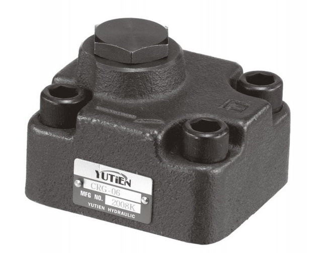
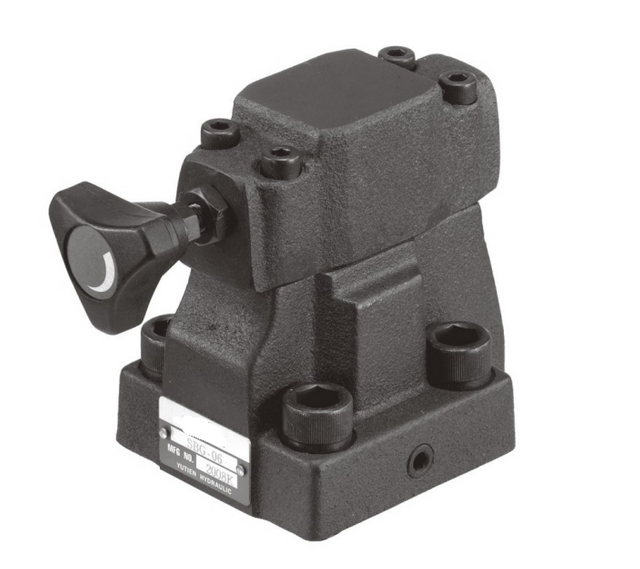
A pressure reducing valve should be chosen after the circuit role is clear. The catalog picture can help later. It should not be the starting point.
Blince sees these questions from the whole circuit side: valves, pumps, motors, cylinders, hoses, fittings, pressure gauges, oil coolers, and the smaller hydraulic parts that often get ignored during a quick repair. That wider view matters because a pressure reducing valve complaint rarely stays neatly inside the valve body.
A cylinder that feels weak may indeed be seeing too little reduced pressure. It may also be waiting for oil that the pump cannot deliver, fighting a tight return line, losing pressure through a directional valve, or being judged from a gauge installed on the wrong side of the circuit. On the other side of the same problem, a small actuator damaged by high pressure may be telling you about an over-set relief valve, a missing reducing valve, or a blocked passage hidden in the valve block.
Blince's guides on hydraulic pressure gauge placement, directional control valve selection, hydraulic cylinder drift, and hydraulic contamination control all point to the same habit: read the working circuit before blaming one component.
This guide applies that habit to hydraulic pressure reducing valves.
A hydraulic pressure reducing valve is installed to keep downstream pressure lower than the pressure available in the main line.
It allows oil to flow into a branch circuit until the downstream pressure reaches the set value. When downstream pressure rises to that setting, the valve throttles or closes enough to prevent further pressure increase. If downstream pressure falls because the actuator moves or leakage occurs, the valve opens again to supply more oil.
That sounds simple, but it changes the circuit in a specific way.
The main system may operate at 180 bar. A small clamp cylinder may need only 60 bar. A pilot circuit may need 30 bar. A brake release line may need a stable reduced pressure while the main pump still supports a heavier function. A pressure reducing valve lets those lower-pressure branches exist inside a higher-pressure hydraulic system.
It does not create extra flow. It does not increase actuator force. It does not protect the pump from overpressure. It does not replace a relief valve in the main pressure line.
A product such as the MPCV Series one way hydraulic pressure control valve belongs in this wider pressure-control conversation, but the correct use depends on the valve function, flow direction, check function, and circuit requirement. Do not select by name alone.
Many wrong repairs come from treating all control valves as the same family of adjustable restrictions.
They are not.
Valve type | Main job | Common misunderstanding |
|---|---|---|
Pressure reducing valve | Maintains lower downstream pressure in a branch circuit | Mistaken for a small relief valve |
Pressure relief valve | Limits maximum pressure by opening to tank or return path | Used when branch pressure should be controlled continuously |
Flow control valve | Controls actuator speed by metering oil flow | Used when the real problem is excessive pressure |
Sequence valve | Opens a second function after pressure reaches a set point | Mistaken for a pressure reducer |
Check valve | Allows flow one way and blocks reverse flow | Expected to regulate pressure when it cannot |
A hydraulic pressure relief valve protects the system from excessive pressure. A pressure reducing valve controls pressure after the valve. If a buyer asks for a "relief valve to lower cylinder pressure," the wording needs to be checked before the part is selected.
The same caution applies to speed complaints. A hydraulic flow control valve may help control actuator speed, but it will not solve a branch pressure problem by itself. Pressure and flow are linked in the machine, but they are not the same setting.

Before choosing a hydraulic pressure reducing valve, describe the actuator being protected.
Is it a small double-acting cylinder? A clamp? A brake release port? A pilot supply line? A rotary actuator? A light-duty hydraulic motor? A secondary function inside a larger valve block?
Then ask what pressure the actuator actually needs.
A hydraulic cylinder is not impressed by the pump's maximum pressure rating. It only responds to the pressure difference across the piston and to the load pushing back through the linkage. Set the reduced pressure too low, and the cylinder may extend in the shop but fail to hold, clamp, or finish the stroke in production. Set it too high, and the same cylinder can mark tooling, overload seals, bend pins, or stress the machine frame.
For a cylinder circuit, write down bore, rod diameter, load direction, linkage ratio, required force, target speed, stroke, and the point in the travel where the load gets worst. A pressure reducing valve adjusted during an easy no-load movement can still disappoint when the linkage reaches the part of the stroke where the machine actually needs force.
For a motor branch, the question changes. A hydraulic motor needs pressure differential and flow, not just a safe-looking inlet pressure. A reducing valve may protect the motor or attachment, but it can also take away the torque the job requires. If the motor slows or stalls after the valve is added, read inlet and outlet pressure together before calling the motor defective.
A reducing valve belongs in the branch where lower pressure is required.
That sounds obvious until the machine has a manifold, sectional valve, shared pump gallery, pilot line, counterbalance valve, and return passages inside one block. The outside hoses may not show what the oil is doing inside.
If the reducing valve is installed before a directional valve, it may reduce pressure for every function fed by that gallery. Installed after the directional valve, it may protect one work port while the other port still sees a different pressure story. Add load holding valves, pilot-operated checks, or counterbalance valves, and the reduced pressure can also change whether a load releases smoothly or refuses to move.
A hydraulic directional control valve makes the decision less obvious because the spool center decides what is blocked, vented, or connected when the lever returns to neutral. Before adding a reducing valve, trace what that directional valve does in neutral, during shift, and at the exact work port you plan to protect.
For compact valve assemblies, a hydraulic multi way control valve may already include relief, check, load holding, or section-specific pressure options. Adding another pressure control valve without understanding the existing valve stack can create a branch that is protected on paper but weak in real work.
A pressure reducing valve cannot be set accurately from the pump outlet gauge alone.
The useful reading is downstream of the reducing valve, near the actuator or branch being controlled. A pump gauge may still show main pressure while the reduced branch is too low, too high, or unstable. This is the same mistake that appears in many hydraulic pressure complaints: one gauge is treated as the whole truth.
Use a liquid filled pressure gauge or test point with a range that makes the reduced setting readable. Trying to set a 25 bar pilot circuit with a 400 bar gauge is a poor bargain. The needle may twitch enough to look alive, but it will not give the resolution needed for a careful adjustment.
The pressure should be checked under the same condition that creates the complaint. If a clamp marks parts only when the oil is hot, test it hot. If a cylinder becomes weak only under load, test it under load. If a pilot line loses pressure only when another function operates, test both functions together.
The article on hydraulic pressure gauge placement is relevant here because pressure before the valve and pressure after the valve tell different stories.
A pressure reducing valve is selected for pressure control, but it still has to pass enough flow.
If the valve is too small, it may create a pressure drop while the actuator moves. The downstream pressure may look correct when the actuator is stopped, then fall when the actuator demands oil. The operator describes the result as weak force, slow movement, or unstable response.
This is common when a replacement valve is chosen by thread size.
Thread size proves the hose can be connected. It does not prove the internal passage, spool design, or flow rating can support the function. A small reducing valve may work on a pilot line and fail on a cylinder feed line.
If the branch flow is high, review the valve's rated flow, pressure drop curve, adjustment range, and expected duty cycle. If the valve has an internal check for reverse flow, confirm whether that check path also has enough capacity for the return or reverse stroke.
A restriction after the reducing valve can also confuse the diagnosis. Undersized hydraulic hoses and fittings may make the reduced branch look weak even when the valve is set correctly.

Heat means hydraulic power is being lost somewhere.
A pressure reducing valve can create heat when it continuously drops pressure while passing flow. Sometimes that is part of its job. But if the valve is forced to meter high flow for long periods, or if a relief valve opens because the reduced branch cannot accept oil properly, the oil temperature may rise quickly.
The complaint may sound like this:
"The new valve protects the small cylinder, but the system runs hotter now."
That does not automatically mean the valve is defective. It may mean the circuit is asking a reducing valve to waste too much pressure energy during normal operation.
Check whether the actuator needs continuous flow or only occasional movement. Check whether a directional valve is holding flow against a reduced branch. Check whether the relief valve opens during the cycle. Check return pressure and cooler pressure drop. A hydraulic oil cooler can help remove heat, but it should not be used to hide a pressure-control mistake.
Blince's hydraulic oil cooler sizing guide is useful when heat appears after a valve change because the cooler is often blamed after the pressure logic has already gone wrong.
The correct valve type depends on flow, pressure stability, response, and accuracy needs.
Valve style | Where it often fits | What to watch |
|---|---|---|
Direct acting pressure reducing valve | Lower flow, simpler circuits, compact branch protection | More pressure variation as flow changes |
Pilot operated pressure reducing valve | Higher flow, better pressure stability, more demanding circuits | Needs correct pilot and drain conditions |
Reducing-relieving valve | Branch pressure must also relieve excess downstream pressure | Tank path and heat must be considered |
Modular or sandwich reducing valve | Compact manifold or directional valve stack | Port logic must match the real circuit |
A direct acting valve may be simple and field-friendly. It can be a good answer for a small branch circuit. A pilot operated valve may hold pressure more steadily at higher flow, but it adds more details: pilot pressure, drain path, contamination sensitivity, and installation direction.
If downstream pressure can rise because of external load, thermal expansion, or cylinder movement, a reducing-relieving function may be needed. Without a relieving path, the reduced branch may still see pressure above the setting after the valve has closed.
That point matters for clamps, suspended loads, and trapped volumes.
A pressure reducing valve is often used to limit cylinder force.
That is useful on clamps, presses, fixtures, light-duty lift functions, and tooling circuits. The valve can protect parts from being crushed or protect a smaller cylinder from the main system pressure.
The risk is setting the pressure from theory and never checking the real mechanism.
A cylinder's required pressure changes with bore area, rod area, load angle, friction, linkage position, and whether the cylinder extends or retracts. A double-acting cylinder may need different pressure behavior on each side. A load holding valve may require enough pilot pressure to release.
If the reduced pressure is too low, the cylinder may move empty but stall under load. If it is too high, the cylinder may move correctly but damage the fixture. If the valve is installed on the wrong port, one direction may be protected while the other still sees full pressure.
When a cylinder drifts, creeps, or loses force after a pressure-control change, compare the case with the hydraulic cylinder drift troubleshooting guide. A pressure reducing valve may expose leakage that was already present.
Pilot circuits often need lower pressure than the main hydraulic system.
A pilot line may shift a valve, release a brake, open a pilot-operated check, or control a variable pump signal. These lines can be sensitive. Too little pressure and the component does not shift or release fully. Too much pressure and seals, spools, or brake components may be damaged.
A reducing valve used in a pilot circuit should be checked for stable pressure, low leakage, contamination tolerance, and proper drain or relieving behavior. A small pressure change can matter more here than it would in a heavy actuator line.
If a valve clicks but the actuator does not move, do not stop at coil voltage. A hydraulic solenoid valve may shift electrically while the pilot or reduced pressure branch fails hydraulically. Measure the pressure at the pilot point before replacing the main valve.
Brake release circuits need special caution. Too low a reduced pressure may drag the brake and create heat. Too high a pressure may damage seals or release behavior. The machine's safety logic should decide the valve, not only the available thread.

A hydraulic pressure reducing valve and a hydraulic pressure relief valve often work in the same system, but they do different jobs.
The relief valve protects the main system from excessive pressure. The reducing valve protects a branch from pressure that is acceptable elsewhere but too high for that branch.
If the main relief setting is lower than the reducing valve setting, the reduced branch may never reach the intended pressure. If the reducing valve is set too close to the main relief pressure, the system may become unstable or heat up as both valves interact. If a downstream load drives pressure back into the reduced branch, the reducing valve may need a relieving function or another protective path.
Do not solve branch pressure by turning the main relief valve down unless the whole machine really should work at lower pressure. That can make other functions weak, slow, or incomplete.
A manual directional valve or multi-way valve with an integrated relief setting should be reviewed before adding another pressure-control valve. The existing relief may already be deciding more than the mechanic realizes.
A pressure reducing valve depends on small internal passages, springs, seats, spools, and sometimes pilot orifices.
Contamination can hold the valve slightly open. It can keep the valve from opening enough. It can damage the seat and let downstream pressure creep upward. It can make a stable branch pressure become jumpy after the oil warms or after a hose replacement.
If the reduced pressure drifts, do not only keep adjusting the screw. Check the oil path.
A valve that changes behavior after a pump failure, hose replacement, tank cleaning, or long storage period should put contamination on the suspect list. The hydraulic contamination control guide explains why clean-looking oil can still carry damaging particles.
If the reducing valve is installed in a compact manifold, dirt may also sit in a passage that cannot be seen from the outside. Cleaning the valve body without flushing the line may lead to the same fault again.
Pressure control does not end at the valve body.
The branch circuit still has hoses, fittings, adapters, quick couplers, actuator ports, return lines, and sometimes coolers or filters. A reducing valve can be correctly selected and still perform poorly if the surrounding hardware creates restriction.
A hydraulic fitting with a small internal bore can reduce flow and create pressure loss. A long hose can add pressure drop. A quick coupler can create a false valve complaint if it is partly seated or undersized.
Return pressure also matters. If the actuator outlet cannot return oil freely, the reduced inlet pressure may not produce the expected force or speed. In cylinder circuits, rod-side pressure can change net force. In motor circuits, outlet pressure reduces usable torque.
The hydraulic quick coupler pressure drop guide is relevant when a pressure-control complaint begins after an attachment or hose change.
Industrial hydraulic power units may use reducing valves for pilot pressure, fixture pressure, clamp circuits, or secondary actuators. The environment may be controlled, but the circuit can be complex.
For a hydraulic system, record main pump pressure, reduced branch pressure, relief setting, valve order, pressure switch logic, and oil temperature. If the branch pressure drops only when another function operates, the issue may be pump flow, valve priority, or gallery pressure rather than the reducing valve alone.
Agricultural machinery often uses multi-way valves, cylinders, hoses, and couplers in dusty field conditions. A pressure reducing valve may be added to protect a lighter attachment or control a specific auxiliary function.
Check whether the valve sees dirt during hose connection. Check whether the reduced branch shares a return with another function. Check whether the operator has adjusted the main relief to compensate for a weak reduced branch. Field repairs can be practical, but pressure settings should still be verified with a gauge.
Attachments may require a lower pressure than the base machine can deliver. A reducing valve may protect a tool, clamp, broom, or auxiliary cylinder.
If the attachment moves slowly after pressure reduction, compare required pressure and required flow. A lower pressure setting may protect the attachment but reduce available force. If the attachment uses a motor, also check outlet pressure and case drain instructions.
Press and clamp circuits are where reducing valves can save parts from damage.
The danger is setting the valve by feel. A clamp that "feels right" at no load may mark real parts. A press that works slowly during setup may overload tooling during production. Use pressure readings and part results together. If repeatability matters, consider whether temperature, leakage, and valve hysteresis are acceptable.
Use this checklist before ordering a hydraulic pressure reducing valve.
Question | Why it matters |
|---|---|
Which branch needs lower pressure? | Prevents reducing the wrong function |
What pressure does the actuator actually need? | Avoids weak movement or damaged parts |
What is the main system pressure? | Confirms the available pressure range |
What is the required flow through the valve? | Prevents pressure drop and heat |
Does downstream pressure need to relieve? | Decides whether reducing-relieving function is needed |
Where will pressure be measured? | Ensures the setting is based on downstream pressure |
Is the valve before or after the directional valve? | Changes which functions are affected |
Are check valves or load holding valves involved? | May change pilot release and trapped pressure |
What oil temperature and viscosity are expected? | Affects leakage and response |
Is the oil clean enough for the valve design? | Prevents drift, sticking, and seat damage |
Are hoses and fittings sized correctly? | Avoids blaming the valve for external restriction |
Is there room for safe adjustment and testing? | Makes future maintenance possible |
If too many answers are unknown, selection can still begin, but it should be treated as a preliminary recommendation. A pressure reducing valve is a control decision, not just a port-matching decision.
Thread size proves the valve can be installed. It does not prove pressure range, flow capacity, response, check function, or reduced pressure stability.
If the new valve has the same thread but a smaller internal path, the actuator may connect correctly and still move weakly or run hot.
A pressure reducing valve set during a cold no-load test may not behave correctly during real work.
Set and verify the reduced pressure with realistic load, oil temperature, and machine function whenever possible. Record the reading instead of relying on screw turns.
Pump pressure does not prove reduced pressure.
Install the gauge downstream of the reducing valve or near the actuator branch being controlled. If the complaint happens at the actuator, the pressure reading belongs near the actuator.
A relief valve limits maximum pressure by opening to tank. A reducing valve maintains lower pressure downstream.
The wrong valve may appear to control pressure during a quick test but fail during continuous operation, load changes, or return pressure changes.
A reducing valve with the correct pressure range can still be too small.
If downstream pressure falls when the actuator moves, check flow capacity and pressure drop. The valve may be throttling more than intended.
If the reduced branch can be pressurized by load movement, thermal expansion, or leakage from another part of the circuit, pressure may rise above the setting after the valve closes.
A reducing-relieving valve or separate protection may be needed.
If reduced pressure drifts, creeps, or jumps, do not keep turning the adjustment screw without checking oil cleanliness.
Dirt in a small passage can make a good valve behave badly.

If you contact a hydraulic supplier, do not send only "need pressure reducing valve."
Send the machine story.
Information | Useful detail |
|---|---|
Machine type | Press, agricultural machine, attachment, industrial power unit, fixture |
Function being controlled | Clamp, cylinder, pilot line, brake release, actuator branch |
Main system pressure | Pump pressure and relief setting |
Required reduced pressure | Target pressure and acceptable range |
Flow requirement | Actuator speed, pump flow, branch flow if known |
Valve position | Before/after directional valve, manifold location, port photos |
Actuator data | Cylinder bore/rod/stroke/load or motor displacement/load |
Symptom | Too much force, weak movement, heat, pressure creep, unstable pressure |
Oil condition | Temperature, viscosity, contamination, water or foam |
Existing valve data | Model, thread, port size, adjustment range, photos |
Recent changes | Pump, hose, coupler, valve, cylinder, oil, filter, manifold work |
This information helps decide whether the next step is a pressure reducing valve, a reducing-relieving valve, a pressure relief adjustment, a flow-control correction, a cylinder leakage test, or a broader hydraulic system review.
A hydraulic pressure reducing valve maintains lower downstream pressure in a branch circuit. It lets one part of the machine operate at reduced pressure while the main hydraulic system can remain at a higher pressure.
No. A relief valve limits maximum system pressure by opening to tank or return when pressure is too high. A pressure reducing valve controls pressure downstream of the valve. They may look similar in a catalog, but they do different jobs.
It should be installed in the branch circuit that needs lower pressure. The exact location depends on whether the valve should affect one actuator port, one directional valve section, a pilot circuit, or a whole downstream gallery.
Use a gauge downstream of the valve, safely run the function under realistic load, and adjust until the downstream pressure matches the required setting. Do not rely only on pump outlet pressure or screw turns.
The reduced pressure may be too low, the valve may be undersized, the actuator may need more force than expected, or there may be flow restriction in hoses, fittings, couplers, or the directional valve. Measure downstream pressure during movement.
Yes. If it continuously drops pressure while passing significant flow, hydraulic power is converted into heat. Excessive heat may indicate wrong valve size, wrong circuit location, leakage, relief flow, or excessive duty cycle.
A reducing-relieving valve can reduce inlet pressure to a lower downstream pressure and also relieve excessive downstream pressure. It is useful when load movement, thermal expansion, or leakage can raise pressure in the reduced branch.
Pressure creep can be caused by contamination, damaged valve seats, internal leakage, trapped downstream pressure, thermal expansion, or an incorrect valve type. The valve and surrounding circuit should both be checked.
Not directly. Speed is mainly controlled by flow. A pressure reducing valve may affect speed if it limits available force or causes pressure drop, but a flow control valve is normally used for speed control.
You need main system pressure, target reduced pressure, flow requirement, actuator type, load, valve location, oil temperature, fluid condition, port requirements, and whether downstream pressure needs a relieving function.
A hydraulic pressure reducing valve is a useful part only when the pressure job is clear.
Do not start with thread size. Start with the actuator, the load, the required reduced pressure, and the point where pressure must be measured. Then check flow capacity, valve location, downstream pressure creep, relief valve interaction, contamination risk, hose restriction, and oil temperature.
If one branch needs lower pressure, reduce that branch. Do not turn down the whole machine unless the whole machine should work at lower pressure.
For hydraulic pressure reducing valve selection or troubleshooting, send Blince the machine function, main pressure, target reduced pressure, actuator data, valve location, pressure readings, oil temperature, and photos of the existing valve block. Blince can review the issue together with hydraulic valves, pumps, cylinders, hoses, fittings, pressure gauges, coolers, and related hydraulic system components before you commit to the next replacement part.
Tel: +86 132 4232 1601
✉️ Email: sales16@blince.com
Website: https://blince.com/
This article is a general engineering guide. Final component selection should be based on machine drawings, measured hydraulic data, working conditions, safety requirements, and confirmation from a qualified hydraulic engineer or supplier.
Blince Hydraulic is an industry-leading company dedicated to precision-engineered fluid power manufacturing and custom hydraulic solutions. Backed by decades of deep field expertise in industrial machinery and thousands of successful global deployments, our engineering team focuses entirely on high-performance hydraulic component manufacturing, including specialized orbital motors, high-pressure travel drives motor, and robust directional control valves. Our production infrastructure utilizes state-of-the-art multi-axis CNC machining systems and is fully ISO 9001 certified to guarantee repeatable volumetric accuracy across every single manufacturing run.
We deliver fast, highly dependable, and cost-efficient hydraulic solutions to heavy industry distributors, machinery OEMs, and maintenance crews across more than 150 countries. Whether your active project calls for a small-volume batch of customized shaft profiles or a large-scale production run of severe-duty cast iron gear pump, we configure our flexible production schedules to meet your target lead times with total pricing predictability. Partnering with Blince means securing maximum system efficiency, elite material quality, and uncompromised fluid power professionalism.
To learn more about our complete product lineup, visit our official website: www.blince.com.