The machine is running. The cylinder reaches the end of its stroke, the pump should settle, and instead the gauge needle hunts. Idle the circuit and the case still warms up. Under load the whole cycle goes soft. The obvious move, at that point, is to find the pressure screw and turn it up.
On a fixed-displacement pump, that screw is usually the relief valve and the fix is straightforward. A variable-displacement axial piston pump hides things better. What looks like a single adjuster can be a pressure compensator, a load-sensing compensator, or a power-limiter pilot — and only one of them is the one you want. Turn the wrong one and the pump hunts, or runs hot, or ends up set past what the prime mover can actually hold.
The short answer is that pressure instability is usually a measurement problem before it is a compensator problem. Record standby pressure, the pressure at which flow visibly de-strokes, the load-sensing margin, loaded flow, and case drain flow before adjusting anything. Then set the flow or load-sensing compensator first and the maximum-pressure compensator second, and only after the pump has been deadheaded with a gauge at the pump outlet.
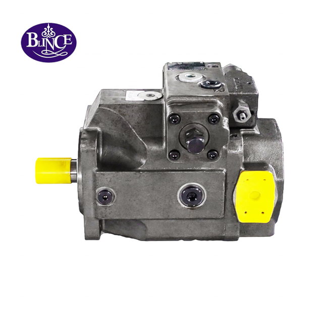
This guide uses the BLINCE PVE series variable displacement axial piston pump as the product anchor, while the compensator and load-sensing principles come from published variable-pump control documentation. The examples assume an open-circuit, pressure-controlled pump. Check the actual control arrangement on your own unit before you touch it.
What Is Published, and What You Still Have to Confirm
Everything below separates a Published figure, a Calculated result, an Example input, and a value that is Unknown / confirm by datasheet. This matters because a compensator setting, a standby value, and a load-sensing margin are all model-specific and cannot be copied from a general article onto a specific machine.
BLINCE product
Published facts used
Source
PVE series
Variable displacement axial piston pump; displacement 60–145 cm³/rev; max flow 80 L/min; peak pressure 420 bar; weight 35 kg; max power 27 kW; speed up to 3000 rpm; cast iron body; 1/2/3-stage options
Two hub pages are worth keeping open: the BLINCE piston pump category for the axial piston and variable series, and the wider hydraulic pump category that covers fixed and variable families together. One caution before we go further. The PVE page describes displacement that adjusts itself to system demand, but it does not publish a load-sensing or pressure-compensator code. Treat the control theory below as general variable-pump behaviour, and take the exact setting and adjustment direction from your own data sheet.
A Pressure Compensator Is a Flow Modulator, Not a Relief Valve
Displacement is set by the swashplate angle. Tilt the plate and each piston travels a shorter or longer stroke per revolution. The published relationship is Q = Vg × n × ηv / 1000 — Q in L/min, Vg in cm³/rev, n in rpm, ηv as a decimal. Push the plate to full stroke and the pump behaves like a fixed unit at maximum flow. Drive it back toward zero angle and displacement drops, and flow drops with it. That ηv term is not a formality. It is where pump efficiency and system efficiency part company, and it decides how much pump-to-drive-motor matching margin is really left once the oil is hot.
Below the set pressure, the plate stays at maximum angle and the pump keeps delivering full flow. Reach the setting and the compensator sends pressure to the control piston, so the plate eases back, flow falls, and what is left is just enough to cover internal leakage and hold the line against whatever is quietly draining away through clearances. This is why a blocked circuit does not blow off the way a relief does: the pump simply stops producing excess flow. That is also why the number you act on has to be measured at the pump's own outlet with a properly placed pressure gauge, and why the setting itself belongs to the wider pump pressure methods rather than a blind turn of a screw.
Pressure Compensator Versus Load-Sensing Compensator
Many variable piston pumps carry two externally similar adjusters, and this is where most misadjustment begins.
A maximum-pressure compensator (PC) limits the highest system pressure. Below the setting the pump runs at full stroke; at the setting it de-strokes to hold pressure. Its standby pressure is the full setting, which is why a PC-only pump can feel hot or stressed when it spends a long time idle against a blocked port. A load-sensing compensator (LS), or flow compensator, instead keeps a roughly constant pressure drop across the metering valve, so pump outlet pressure becomes load pressure plus that margin. The two ideas are covered in the same variable displacement pump primer and the types and applications reference.
When the machine is idle, the LS pilot drives the pump toward a low standby pressure, often in the low tens of bar, instead of the full maximum setting. The result is less heat and lower seal loading during idle. The distinction matters for the setting order and for diagnosis: a pressure compensator sets the ceiling, while a load-sensing valve sets the margin and the low standby. Turning the LS adjuster while believing it is the maximum-pressure adjuster produces the classic symptom of an unstable, overshooting, or soft pump, and on some units it can push the pump above the intended operating envelope. The idle temperature you see is the same signal discussed in oil viscosity selection and in the heat load that a power unit sizing exercise has to account for.
Which Control Does Your Pump Have
Before adjusting, identify the control arrangement from the model code, the nameplate, and the number and position of the pilot ports. This is a reading task, not a guess, and the same care applies when the pump is part of a packaged unit rather than a bare component.
A single compensator with one adjuster and no separate LS or remote pilot port is usually pressure compensation only.
Two adjusters, or a small pilot valve stacked on or near the main compensator with an LS port to the downstream metering valve, usually means pressure compensation plus load sensing or a remote/flow compensator.
A pump labelled for "dual-stage pressure compensation" may use a two-step pressure control rather than load sensing. The BLINCE A7V series is published with this wording, the A4V axial variable displacement pump covers larger-frame variable displacement for industrial service, and the A10 series is the high-flow variable option.
If the model code, the LS line, and the control drawing are not available, stop and obtain them. A machine category is a selection clue, not a compatibility conclusion.
Measure Before You Turn
The gauge must read the pump, not a remote point downstream of a valve, filter, or long hose run. Put a test gauge at the pump outlet test port, and record pressure at three states: unloaded/idle, deadheaded, and loaded against a known work function. The tap location changes the number, which is why pressure gauge placement and false readings is worth reviewing before you trust a reading.
Record standby pressure, the de-stroke pressure where flow visibly drops, the load-sensing margin for an LS pump, loaded flow, and case drain flow — all before you adjust anything. Two readings do most of the separating work: deadheaded standby pressure, and case drain flow once the oil is at temperature. If standby comes up to the right value and holds, yet the machine still falls down under load, the compensator is probably not the culprit, and the time you spend turning it will only move a number that was already correct. The piston pump case drain guide explains how drain flow and heat point to internal leakage, and the pressure methods reference walks through the loaded and deadheaded checks in sequence.
Worked Example: Flow, Power, and Why Max Pressure and Max Flow Do Not Happen Together
Two published maximums on a data sheet do not mean they occur at the same time. The PVE page lists 80 L/min, 420 bar, and 27 kW. Power follows pressure and flow together: P = p × Q / 600, with P in kW, p in bar, and Q in L/min.
Work it backwards for those numbers. At 420 bar, 27 kW buys only Q = 27 × 600 / 420 = 38.6 L/min (Calculated). Run 80 L/min instead and the same 27 kW tops out near 202 bar. Nothing is broken here. Max flow, max pressure, and max power are three separate limits, and the compensator works inside whatever the prime mover can supply. When the pump de-strokes on rising pressure, it is shielding the drive from a demand it cannot meet — the exact boundary a power unit sizing or pump-to-motor matching check is meant to catch.
Displacement and speed combine the same way. Take 45 cm³/rev turning at 1500 rpm with ηv = 0.95 (Example inputs): Q = 45 × 1500 × 0.95 / 1000 = 64.1 L/min. Say the machine wants 65 L/min. At that displacement and speed it will not get there, and no compensator turn will find the missing litre — the answer sits in drive speed, displacement setting, or volumetric efficiency. A hot, thin oil pulls ηv down, which turns it into a pump versus system efficiency question and a viscosity grade question at once.
Now put load sensing beside it. A 160-bar load with a 15-bar margin should hold the pump outlet near 175 bar while the function moves, nowhere near a 420-bar ceiling. That margin is the number that tells you whether the pump is following the load or just leaning on the ceiling.
Decision Table: Symptom to Check to Likely Cause
Work down the symptom, and confirm the direction with the measurement before reaching for an adjuster.
Observed condition
Likely direction
First check
Data that confirms or rules it out
Pressure hunts or oscillates around a setting
LS/flow compensator misadjusted, air in the pilot line, or a contaminated compensator
Bleed the pilot line and check LS plumbing
Stable pressure after bleeding; repeatable margin across cold/hot
Pump won't reach rated pressure
Compensator set low, worn rotating group, or a prime mover that cannot hold the load
Deadhead with a gauge at the pump outlet
Standby pressure vs the nameplate setting; case drain flow at temperature
Slow or soft cycle under load
Early de-stroking, restricted inlet, or internal leakage
Measure loaded flow and inlet vacuum together
Flow-vs-pressure slope; drain flow; inlet vacuum within limits
Hot at idle
High standby pressure or a relief/pilot path leaking to tank
Record standby pressure and case temperature
Standby near the full PC setting vs a low LS standby
Fine cold, unstable hot
Viscosity change or contamination settling
Repeat the same measurements at two oil temperatures
Margin or standby drift; drain flow rise with temperature
Loud noise or pressure spikes
Pilot instability, trapped air, or inlet starvation
Check reservoir, inlet restriction, and fluid level
Noise clears after inlet/pilot correction
System Conditions That Change the Setting
The correct compensator setting is not a fixed number that survives every change in the circuit. Four system conditions move the answer, and each is worth checking before you commit to a pressure value.
Oil temperature and viscosity. A margin or standby that is correct at a hot, thin oil may read differently on a cold start, because the control's response and the internal leakage both move with viscosity. The hydraulic oil viscosity guide covers the grade selection and the temperature window you should hold while adjusting.
Contamination. A particle lodged in a small pilot orifice or compensator spool makes the pump hunt or stick, and no amount of screw turning removes the particle. Check the filter and the pilot circuit, and use the contamination control guide to decide whether a flush is the real fix.
Prime mover and drive. A compensator set near or above the drive's power limit will stall or lug the engine or motor, and the pump will de-stroke in a way that looks like instability. Confirm available speed and power first, then set pressure within the envelope rather than against it.
Inlet and return conditions. A restricted inlet or a small air leak can imitate a control fault, complete with noise and pressure spikes. When the symptom shifts with reservoir level, inlet temperature, or a fresh filter, put the inlet on the suspect list before the compensator.
How to Set the Compensators in the Right Order
Order matters here. Flow or load-sensing compensator first, maximum-pressure compensator second, and no adjustment at all without a gauge at the pump outlet.
Isolate and shut down before anything else. Follow the machine manual for blocked-port and stored-energy procedures.
Fit a test gauge at the pump outlet test port, not at a remote valve.
Deadhead the pump with the circuit blocked or the loading valve placed in its idle position, exactly as the manual requires.
Set the load-sensing or flow compensator first. With the pump idling against the blocked port, adjust the LS/flow setting to the desired low standby or margin. Many controls are factory set to a low standby of roughly 15–30 bar, but confirm the value for your model.
Then set the maximum-pressure compensator. Energize or open the loading path so pressure can build against the compensator, and adjust the maximum pressure to the required ceiling, still watching the outlet gauge.
Recheck cold and hot. Each cycle should end with the pump back at the intended standby.
Clockwise usually raises the setting and counter-clockwise lowers it, though the direction depends on the control. Confirm it from the drawing, or watch the gauge as you make a small adjustment. Do not exceed the published maximum pressure or the prime mover's power limit, and do not set the ceiling above the pressure the system components are rated to hold.
Common Mistakes and What They Actually Cost
The mistakes below look reasonable and still cause real damage.
Treating the two adjusters as interchangeable. The flow/load-sensing adjuster and the maximum-pressure adjuster look similar and sit close together. Turning the LS adjuster to raise "maximum pressure" changes the margin and the standby instead, which is the usual cause of hunting and overshoot.
Setting pressure without deadheading or without a pump-side gauge. A reading taken downstream of a throttled valve or a filter is not the pump's compensator pressure. The setting is then made against a false number and repeated on the next shift.
Raising pressure to recover lost flow. If the pump has lost volumetric efficiency, higher pressure makes the leakage worse and heats the oil. The symptom improves for a moment and then returns worse.
Ignoring the standby value. A PC pump held at full setting through long idle periods wastes energy and loads the seals; an LS pump that will not drop to low standby has a pilot or plumbing fault that is worth finding.
Adjusting hot and expecting cold stability. Viscosity moves with temperature. A margin or standby set only at a hot reading may behave differently on a cold start, so both states have to be checked.
When You Should Stop and Not Adjust
There are cases where turning a screw is the wrong next step.
The complete model code, control type, and control drawing are not available.
You cannot measure standby, loaded, and deadheaded pressure at the pump outlet.
The problem appears only in a safety-critical, personnel-lifting, braking, or suspended-load function, and the required machine procedure and approved circuit architecture are not in front of you.
Loaded flow and case drain flow have not been measured, so internal wear cannot be separated from a control fault.
The prime mover cannot hold rated speed or voltage, so the pump is being under-driven before any hydraulic setting is at fault.
In each case the correct move is to collect the missing evidence first. A machine category is not a compatibility conclusion, and a pressure setting is not a substitute for a measured flow curve.
What to Send With an Inquiry
When the pump still misbehaves after the measurements, the following fields make a quote or a technical review meaningful rather than a guess.
Pump and control: complete model code, displacement, control type, rotation, ports, and any pilot/remote connections.
Duty and performance: drive speed, required flow, continuous / intermittent / peak pressure, standby pressure, and the load-sensing margin if applicable.
Fluid and environment: oil type, viscosity grade, cleanliness target, start / normal / maximum oil temperature, and ambient conditions.
Measurements: outlet pressure at idle, deadheaded, and loaded states; loaded flow; case drain flow at two temperatures; inlet vacuum.
Evidence: nameplate photos, the control drawing, a short video of the pressure gauge during the fault, and any previous failure debris or repair history.
BLINCE can then return a candidate direction — which control is misadjusted, which measurement is missing, an incompatible interface, a likely internal-wear boundary, or the reason the quotation should wait — before committing to a part number.
What is the actual difference between a pressure compensator and a load-sensing valve?
The pressure compensator caps the maximum system pressure by de-stroking the pump at its setting. The load-sensing valve holds a constant pressure drop across the metering valve, so pump pressure tracks load plus margin and can fall to a low standby at idle.
Which adjustment do I turn first?
Set the load-sensing or flow compensator first to establish the standby and margin, then set the maximum-pressure compensator against the ceiling. Confirm both cold and hot.
What should standby pressure be?
It is model-specific. Many load-sensing controls use a low standby of roughly 15–30 bar, while a plain pressure-compensated pump holds the full setting at standby. Read the value for your model and control code.
What makes a variable pump run hot while it is idling?
On a pressure-compensated pump, idle still means the circuit sits at the full setting, even at almost no flow. If a load-sensing pump runs hot at idle, it is usually not dropping to its low standby — a pilot or relief path is letting pressure through when it should not.
How can I tell a worn pump from a misadjusted compensator?
Compare deadheaded standby pressure against the intended setting and measure case drain flow at temperature. If the pump reaches and holds pressure but flow is short under load, internal leakage is the more likely direction.
Can I set the pressure above the published maximum?
No. The published maximum, the system component ratings, and the prime mover's power limit all cap the setting. Exceeding them can damage the pump, the machine, and anyone near a stored-energy failure.
This article is a general engineering guide. Final component selection should be based on machine drawings, measured hydraulic data, working conditions, safety requirements, and confirmation from a qualified hydraulic engineer or supplier.
Blince Hydraulic Team
Blince Hydraulic is an industry-leading company dedicated to precision-engineered fluid power manufacturing and custom hydraulic solutions. Backed by decades of deep field expertise in industrial machinery and thousands of successful global deployments, our engineering team focuses entirely on high-performance hydraulic component manufacturing, including specialized orbital motors, high-pressure travel drives motor, and robust directional control valves. Our production infrastructure utilizes state-of-the-art multi-axis CNC machining systems and is fully ISO 9001 certified to guarantee repeatable volumetric accuracy across every single manufacturing run.
We deliver fast, highly dependable, and cost-efficient hydraulic solutions to heavy industry distributors, machinery OEMs, and maintenance crews across more than 150 countries. Whether your active project calls for a small-volume batch of customized shaft profiles or a large-scale production run of severe-duty cast iron gear pump, we configure our flexible production schedules to meet your target lead times with total pricing predictability. Partnering with Blince means securing maximum system efficiency, elite material quality, and uncompromised fluid power professionalism.
To learn more about our complete product lineup, visit our official website: www.blince.com.