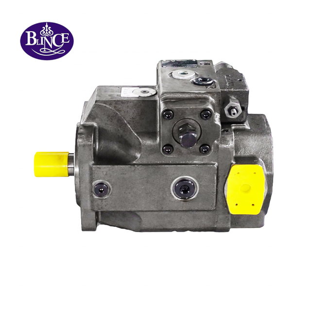
Twenty minutes into a shift, a hydrostatic travel drive that pulled cleanly from cold starts to fade. The lever position has not changed. What changes is the sound: the motor is a little rougher at high swivel angle, the case drain line is warmer than the return line, and a slope the machine climbed in the morning now needs a second attempt. By the time the complaint reaches the workshop, three suspects have already been named, and the most expensive one is usually named first.
That order is understandable. High pressure and precision surfaces make the rotating group the part people can picture, and when the machine stops performing, it is the first component they name. The hydraulic motor range shows why that picture can mislead: architecture decides which failure modes are even possible, and the field notes on weak motor performance keep returning to the same theme, that speed loss has more than one owner.
What makes the diagnosis harder is that an axial piston motor is the only component in a hydrostatic drive that depends on a continuous supply of low-pressure oil it does not generate itself. In a closed circuit, that supply comes from the charge pump. When charge pressure, filtration, cooling, or the mechanical drive changes, the motor reports the problem through the same three symptoms a worn motor produces: lower speed, lower torque, and higher case drain temperature. Torque values, tolerances, and adjustment limits belong to the exact machine manual and the motor data sheet for the unit on the machine.
The Short Answer, With Its Conditions
If an axial piston motor has lost speed and torque but its case drain flow is still close to the level it showed when the machine was healthy, the motor is probably not the failed part. Look first at charge pressure and at the differential between charge pressure and case pressure, then at filtration, oil temperature, and the mechanical drive between motor and load. The motor test sequence is the right instrument for that early comparison, and the case drain pressure notes explain why the drain line is often the first place a hidden fault becomes visible.
If case drain flow has risen substantially at the same oil temperature and pressure, and the rise is not explained by a flushing valve or by pump leakage sharing the same drain line, the rotating group has earned the suspicion. The condition that makes this answer valid is measurement at the temperature and pressure where the operator sees the fault; a motor tested cold and unloaded will pass a leakage test that means almost nothing, which is the central argument of the viscosity reference applied to a warm machine.
The boundary is this: case drain flow proves leakage, not its location. On a closed-circuit machine, the drain line commonly carries motor leakage, pump leakage, and the flow from a loop flushing valve. Unless you know what else is discharging into that line, a high reading can convict the wrong component, which is why the pump-side drain guide belongs in the same file. The explanation of case drain function is the background for readers who are meeting the port for the first time.
The first action is therefore not a disassembly. It is a two-point measurement campaign: case drain flow and case drain temperature at the complaint condition, plus charge pressure measured against case pressure, recorded twice — once with the oil cold and once with the oil at normal working temperature.
What Is Already Known Before You Measure
Evidence boundary. The product facts below are published on current BLINCE pages. The circuit relationships come from OEM application documentation (Bosch Rexroth axial piston documentation and a Danfoss hydrostatic transmission applications manual). The worked numbers are labelled as examples or calculations and are not performance promises for any specific machine.
Bent-axis axial piston motors are rated by displacement, and the BLINCE A2FO fixed bent-axis motor is published with a displacement range of about 45–90 cm³/rev, a rated pressure of 400 bar, a peak pressure of 450 bar, common operating speeds between 2,000 and 6,000 rpm, a maximum speed of roughly 6,000–8,000 rpm, and a stated working temperature range of −40 to +115 °C. Those figures place it in the heavy-duty segment where speed and torque are set by flow and pressure difference rather than by the motor alone, and where the selection guide for axial piston motors is a better starting point than a troubleshooting page when the machine never worked correctly.
Variable motors behave differently again, because displacement becomes a control variable. The BLINCE A6VM angled-axis variable motor is published with a continuous pressure of approximately 400 bar and peak pressure of 450–500 bar, with control options that include hydraulic and electric proportional control, two-position switching, high-pressure-related automatic control, and speed feedback. When a variable motor loses speed at a command position that used to work, the control and its command pressure belong in the axial piston motor category review from the start, not at the end.
Parker Hannifin, in its published motor selection white paper, classifies bent-axis piston motors as high-speed, high-torque units known for high pressure capability, high speeds, and volumetric and mechanical efficiencies in the 97–98% range. That published range is useful as a benchmark for the leakage calculation later in this article, with one caution: published efficiency is measured under defined conditions, not on your machine, with your oil, at your case pressure.
Why an Axial Piston Motor Fails Differently From an Orbital Motor
An orbital motor and an axial piston motor can both be described as hydraulic motors, and that is roughly where the similarity ends when a machine starts losing performance. The orbital motor is compact, tolerant of a wide viscosity range, and comparatively inexpensive to replace, which shapes how technicians treat it: measure, then swap. The axial piston motor range sits at the other end of the same decision, because a variable displacement unit is a controlled, high-pressure device whose internal clearances, hold-down forces, and control pressures are all part of the circuit's behaviour.
The practical consequence is that fewer faults on an axial piston motor are "inside the motor" than the symptom suggests. Rexroth's axial piston unit documentation opens its troubleshooting chapter with an instruction that is easy to skip and expensive to ignore: work systematically, because random removal and readjustment of settings can destroy the evidence of the original cause. The same documentation asks the technician to establish whether the unit worked correctly in the whole system before the problem, and what has changed since — operating conditions, maintenance, repairs, upgrades, hydraulic fluid.
That is why this article starts with a change log and a temperature comparison rather than with a teardown. Coupling wear is a particularly efficient impostor, because a loose or misaligned drive produces the same speed complaint as a worn motor; the spline and coupling checks take less than an hour and cost nothing. The guide to gradual motor performance loss follows the same sequence for machines where the complaint arrived gradually rather than suddenly.
Four Questions That Order the Whole Diagnosis
Question 1: Was it ever right? If the machine ran correctly for months and then changed, the fault is an event: a filter bypass, a failed cooler fan, a replaced hose with a smaller bore, a control linkage that drifted, a load that grew. If the machine never worked correctly after a build or a swap, the fault is a specification problem: displacement, control type, flushing flow, drain routing, or heat load. The selection guide covers the second case, and the field test steps for a hydraulic motor cover the first.
Question 2: Does it fade only when the oil is hot? Cold oil is thick, so internal leakage is low and a worn motor can look healthy for the first fifteen minutes. As the oil warms, viscosity falls, leakage rises, and speed drops. The guide to hydraulic oil viscosity explains why the same clearance leaks more at 70 °C than at 25 °C, and the motor hub lists the architectures whose published temperature and viscosity tolerance differ most.
Question 3: Does it fade with pressure or with time? Load-related fading points toward leakage or a pressure-setting problem. Time-related fading points toward heat, filtration, or cooling. A motor that holds speed in the morning and loses it after thirty minutes of continuous work is describing a thermal loop, not a broken gear tooth, and the case temperature and cooling reference traces that heat path through to the cooler. The case drain pressure reference shows how the same loop damages shaft seals and repeats the failure.
Question 4: What is the case drain doing? Case drain flow is the only reading that directly observes internal leakage during operation, so it deserves its own calculation rather than a glance at the return line. The motor test method covers the general sequence, and the case drain function explained covers why that flow exists at all. The next sections adapt both for an axial piston unit in a closed circuit, where the drain line is shared.
Where to Connect Gauges and the Flow Meter
Before any number is worth recording, the measurement points have to be right. On a closed-circuit axial piston installation there are four pressure locations that matter and one flow location: high-pressure loop ports A and B, charge or boost pressure, case pressure at the highest drain port (commonly marked T1, T2 or U on axial piston units), and case drain flow measured in the drain line on its way to the reservoir. The order of the readings is set out in the sequence of a loaded motor test, and the pump case drain guide shows how the same ports are read on the other half of the transmission.
Two details change the reading. First, the drain line must be at its highest available port and must run back to the reservoir, not into a pressurised return manifold, or the case pressure you measure will include somebody else's back pressure. The function of the case drain port explains that line; the routing rules come from the machine and motor documentation, and the recorded drain pressure failure patterns show what appears when they are ignored.
Second, in a closed circuit the drain flow is a combination. The Rexroth drain-routing instruction for multiple units is explicit that a shared drain line must not exceed the lowest permissible case pressure of any connected unit in any situation. If a piston pump and the motor share a drain line, and the pump's own clearance leakage rises, the motor's case drain reading rises with it — a mechanism the piston pump drain guide documents from the pump side and the viscosity guide explains in terms of clearance and film thickness.
Record five values at each test point, not one: oil temperature at the reservoir, case drain temperature, shaft speed, loop pressure difference, and case drain flow. Temperature without pressure, or pressure without temperature, produces readings that other people cannot reproduce. A leakage number nobody can reproduce is not evidence, and the bench and field test routine is built around exactly that discipline, while the case drain function article explains what the flow is actually doing inside the housing.
Measurement One: Case Drain Flow and the Leakage Calculation
This is the calculation that separates a worn rotating group from a starved one, and it needs four inputs.
Input
Symbol
Value used in this example
Identity
Motor displacement
V
80 cm³/rev
Example size inside the published A2FO 45–90 cm³/rev range
Shaft speed under load
n
1,500 rpm
Measured with a tachometer or from a verified control signal
Case drain flow at 350 bar and 55 °C oil
Q_case
6.0 L/min
Measured with an inline flow meter in the drain line
Loop flushing valve flow
Q_flush
2.0 L/min
Example; confirm from the machine drawing or valve data sheet
Step 1 — theoretical flow through the motor. A motor displacing 80 cm³ per revolution and turning at 1,500 rpm would consume:
Q_th = V × n ÷ 1,000 = 80 × 1,500 ÷ 1,000 = 120 L/min
Step 2 — leakage attributable to the rotating group. The measured case drain includes the flushing valve flow, so remove it before judging the motor:
That is inside the published 97–98% range for healthy bent-axis piston motors, measured here at a case drain temperature of about 55 °C. Now repeat the same test with the oil at its normal working temperature, say 80 °C, with the same load: the case drain reads 9.0 L/min. Subtracting the same 2.0 L/min of flushing flow leaves 7.0 L/min, and η_v falls to about 94%. The motor is still usable in many applications, but the trend is now documented rather than argued about, and the next scheduled test has a baseline. The case drain pressure notes and the viscosity guide are the two references that turn those two readings into a judgement instead of a guess.
For contrast, consider the same machine with a case drain of 14 L/min at 80 °C. Removing 2.0 L/min of flushing flow leaves 12.0 L/min of leakage, η_v ≈ 90%, and the rotating group becomes the leading suspect. At 22 L/min the estimate falls to about 83%, a level at which reduced speed, rising case temperature, and torque loss usually appear together. The checklist of system causes for weak output must be cleared before that conclusion is written down, and the contamination control guide explains how quickly a wear particle can move a healthy unit into that range.
Cross-check with torque. Theoretical torque is a function of pressure difference and displacement:
T_th = Δp × V ÷ 62.8 = 350 × 80 ÷ 62.8 ≈ 446 Nm (theoretical, with no losses)
At an overall efficiency of about 0.95 the usable figure is roughly 424 Nm. If the machine stalls below that figure at the same pressure difference, either the load has grown or part of the pressure is being spent somewhere other than the motor — a relief valve cracking early, a restriction in a hose, or a counterbalance setting that no longer matches the load. The loaded test method separates shaft output from circuit losses, and the selection guide shows which of those losses are designed in rather than failed.
What the calculation does not prove. It does not tell you whether the leakage is past the piston shoes, the valve plate, the control piston, or the shaft seal, because those paths cannot be separated from outside the motor. That separation requires disassembly on a bench with the manufacturer's limits, or an exchange decision made on trend rather than on a single reading. The external drive inspection notes cover the external half of that question, and the seal failure case notes cover the seal failure that looks like an internal one.
Reading the Numbers: What the Result Rules In and Out
Take the two results from the previous section and apply them in order. A leakage estimate near the published range, measured at working temperature and working pressure, with a case drain that is not bubbly and a case temperature that is stable, moves the motor down the suspect list. The next suspects are charge pressure, filtration, cooling, and the mechanical drive — all cheaper to inspect than a motor exchange, and all capable of producing the identical complaint. The temperature management reference and the contamination control guide cover those two suspects in detail.
A leakage estimate that has clearly drifted, combined with a case drain temperature that climbs faster than the reservoir temperature, points to the rotating group. Before ordering, two more checks belong in the file: shaft and spline condition, and coupling alignment. The spline shaft wear guide explains how a worn coupling fit mimics a motor fault and why the replacement motor then fails in the same way, which is the most expensive version of this diagnosis, and the viscosity guide rules out the fluid as the cause of the drift.
There is a third possibility that fits neither column and is frequently missed on machines with a variable motor: the displacement control is not reaching the commanded angle. The motor is hydraulically sound and the loop is pressurised correctly, but the swivel angle stays at minimum, so the machine runs at high speed and low torque regardless of what the lever says. Rexroth's documentation for variable axial piston motors lists insufficient pilot or control pressure and a defective control device among the causes of "rotational speed or torque cannot be reached", alongside internal wear. On an A6VM variable motor installation, confirming coil voltage, command signal, and control pressure takes minutes, and the axial piston selection guide explains why control type changes the expected response in the first place.
Charge Pressure: The Fault That Copies a Worn Motor
Charge pressure is the part of a closed-circuit drive that technicians respect in theory and skip in practice. Danfoss's hydrostatic transmission applications manual lists what the charge pump actually does: it replenishes loop fluid lost through the volumetric inefficiency of the pump and motor, replaces fluid removed by the flushing valve, makes up fluid for load-induced bulk modulus effects, supplies flow to stroke servo control pistons, and feeds auxiliary functions such as brake release. Its pressure functions are just as concrete — maintaining the low loop pressure that provides hold-down forces on the rotating groups, activating the servo control, and controlling flushing flow through the differential between the charge relief valve and the loop flushing relief valve. The case drain function article shows where that replenished oil ends up inside the housing, and the motor hub shows how many architectures depend on it.
Read that list again with a failed charge pump in mind. Loss of charge pressure removes the hold-down force that keeps the rotating group seated, starves the control that sets displacement, and reduces flushing flow that carries heat out of the case. The motor's observable behaviour is then reduced speed, reduced torque, rising case temperature, and increasing noise — the classic description of a worn motor. It is not the motor. Replacing the motor in this condition installs a new rotating group into the same damaged circuit, and the second failure arrives faster than the first. The repeat-failure case notes document that pattern, and the oil temperature reference shows how the heat accumulates while the cause is still being discussed.
The measurement detail that matters most is not charge pressure on its own but charge pressure above case pressure. Danfoss states that with an integral charge pump the charge relief valve is referenced to case pressure, so the relevant charge pressure is the differential above case pressure, and that failing to maintain this differential may result in damage to the unit. A machine with a 24 bar charge reading and a 12 bar case reading has less usable charge pressure than the gauge implies. High case pressure can come from a restricted drain line, a shared drain manifold, a check valve installed in the drain line, or an above-reservoir installation that was never re-checked after a modification, and the pump case drain guide follows the shared-line case through to the reservoir.
For the same reason, case pressure has its own limit that has nothing to do with performance. Rexroth's axial piston documentation for the A2FO family gives a mean differential pressure of 2 bar between case and ambient pressure that may not be continuously exceeded at normal operating temperature, with momentary spikes below 0.1 s up to 10 bar permitted and a requirement that case pressure stays at or above ambient pressure. Those are published limits for that component family, and they are the reason a technician who raises case pressure to "improve flushing" is trading a performance problem for a shaft seal failure — a trade the case pressure limit notes describe in detail, and one that the A2FO published data range puts in context for a specific bent-axis motor.
Swashplate, Bent-Axis and Control Wear: Which Part Produces Which Symptom
Inside an axial piston motor, several components wear on different time scales, and they do not all produce the same complaint. Knowing which signature belongs to which group shortens the bench work even when the final judgement still requires disassembly. The contamination control guide matters here more than in most hydraulic topics, because debris arrives at these surfaces before it reaches any filter indicator, and the oil temperature reference covers the second mechanism that accelerates the same wear.
The valve plate or control plate and the cylinder barrel face is the pair that most directly changes efficiency. Scoring or wear here increases internal leakage continuously and produces rising case drain flow with falling speed, and the leakage is worse when the oil is thin. Danfoss recommends fluid cleanliness of ISO 22/18/13 or better for hydrostatic transmission circuits, and high-temperature operation pushes the requirement further. The seal damage mechanism follows from the same leakage path, while the viscosity reference explains the oil-thickness half of the sentence.
Piston shoes and the running surface they bear against produce a different pattern. Early wear shows as a motor that becomes noisy under pressure and hot in the case while still holding speed reasonably well; later wear produces metal in the filter and a rapid increase in leakage. Bearings and the shaft support produce vibration, runout, and seal leakage rather than torque loss, which is the pattern the slow-running motor reference treats as a mechanical rather than a hydraulic complaint, and the coupling and spline wear notes cover the external components that produce identical noise.
The control piston and servo on a variable motor produce position errors — the motor runs, but not at the displacement commanded — and can fail without any change in case drain flow at all. The A6VM product page lists the published control options for that family, which is the fastest way to identify what the machine is actually commanding, while the selection notes for axial piston units set out how control type changes the response the operator should expect.
Shaft seals sit at the end of this list for a reason. A seal leak is a symptom of case pressure, speed, temperature, or a scored shaft, not usually the original fault. Rexroth notes that the service life of the shaft seal is influenced by rotational speed and by case pressure, which is the technical version of the same warning: replacing the seal without correcting the case pressure condition repeats the failure. The guide to case drain pressure and repeat motor failure carries that loop through to the repair decision, and the pump-side drain guide shows how a shared drain line carries the problem between units.
Decision Table: Symptom, Measurement, and Next Action
Use the table to route the diagnosis. Each row assumes the machine is at working temperature and under the load that produces the complaint.
Observed condition
Likely direction
Measurement that confirms it
Action that follows
Speed and torque fade only when oil is hot
Internal leakage or wrong viscosity
Case drain flow at two temperatures; oil grade against the machine requirement
Compare η_v at 55 °C and 80 °C; verify the fluid before condemning the motor
Speed drops under load but recovers at low load
Leakage, pressure setting, or relief bypass
Loop pressure difference at the motor; case drain flow under load
Check relief and compensator settings before opening the motor
Case drain flow high immediately from cold
Drain routing or shared leakage
Drain line path, flushing valve flow, pump case drain
Separate the flows; do not yet attribute the reading to the motor
Case temperature rises faster than reservoir temperature
Flushing flow, cooling, or internal leakage
Case temperature, flushing flow, cooler performance
Verify flushing circuit and cooler before an exchange
Motor runs but will not hold the commanded displacement
Control or pilot pressure
Control pressure against the data sheet; command signal at the valve
Repair or exchange the control device
Noise appears only at high pressure
Air in the loop or worn running surfaces
Case drain for bubbles; filtration history; pressure at complaint point
Bleed and check filtration, then reassess
Forward and reverse behave differently
Directional control, relief, or one-sided wear
Pressure and speed in both directions at the same load
Isolate the control side before the rotating group
Metal found in the filter or drain oil
Mechanical damage
Debris inspection, filter cut, oil sample
Stop running; the circuit needs cleaning as well as repair
Two rows deserve emphasis because they are the most common false convictions. The first is a high case drain reading measured on a cold machine: the number is real, and it is measuring viscosity rather than wear — the viscosity guide and the how-to-test reference together define the correct comparison. The second is a control pressure fault on a variable motor, where torque loss, speed loss, and a hot case all appear while the rotating group is intact; a gauge and the drain pressure figures resolve that one, provided the control pressure is recorded on the same sheet.
Two Tradeoffs That Change the Repair Decision
Tradeoff one: repair the rotating group, exchange the complete motor, or reduce the duty. Rebuilding an axial piston motor is a precision operation on a component whose clearances and hold-down forces determine whether it survives its next thousand hours. An exchange unit removes that risk but costs more up front and requires the complete model code, control type, and displacement to be identified from the nameplate rather than from memory. A third option — keeping the existing motor and reducing duty cycle, speed, or pressure — is sometimes defensible on a machine near the end of its service life, provided the case drain trend is monitored and the temperature stays inside limits. Where duty reduction is the choice, the selection guide and the axial piston motor range define what the reduced duty still has to satisfy.
Tradeoff two: add cooling and filtration, or correct the mechanism. Larger coolers and finer filters protect a motor that is being damaged, and they are often the least disruptive first step. They do not remove the wear particle source, and a cooler sized to hide a leakage-generated heat load will not restore lost torque. Danfoss's applications manual uses a rough sizing convention of selecting a heat exchanger rated at about one third of the machine's horsepower for hydrostatic transmissions, which is a starting convention for a system review rather than a substitute for measuring the actual heat load. The contamination control guide covers filtration targets and the oil temperature reference covers the heat balance.
The reason this matters to the repair decision is heat arithmetic. Every pressure drop in the circuit converts hydraulic power into heat:
P_loss = Δp × Q ÷ 600
For a restriction that costs 20 bar at 60 L/min, P_loss = 20 × 60 ÷ 600 = 2.0 kW. That figure has to leave the oil through a cooler or the reservoir. On a machine whose cooler was sized for the original load, an extra 2 kW is often the difference between stable temperature and a thermal loop that shortens motor life. The heat balance reference covers the system side of that balance, while the viscosity reference covers what happens to the fluid when the balance is lost.
Application Checks Before You Accept a Replacement Motor
A replacement axial piston motor that does not match the installation will produce a new problem rather than solving the old one. Before the order is placed, confirm the items below against the nameplate, the machine drawing, and the current data sheet. The selection guide walks through the same list in selection order, and the shaft and coupling inspection notes cover the mechanical interface that is most often misread.
Displacement and control type come first, because a variable motor with the wrong control is not interchangeable with the original even at identical displacement. Rotation direction, port positions, and mounting flange follow. Then the hydraulic details: rated and peak pressure against the machine's actual pressure profile, allowable case pressure against the measured case pressure, and the case drain routing — the subject of the drain routing limits and of the explanation of the drain port.
Finally the fluid and environment: viscosity grade at working temperature, cleanliness level actually achieved, ambient and case temperature, and available cooling capacity. The contamination control guide defines the cleanliness value that most often disqualifies an otherwise correct replacement, and the viscosity grade is settled by the machine requirement rather than by what is available in the drum. Two BLINCE products illustrate the range being compared: the A2FO fixed bent-axis motor for applications where displacement is fixed and speed is set by flow, and the A6VM variable motor for machines that need displacement under command.
Common Mistakes That Send Good Motors to the Scrap Bin
The first mistake is measuring case drain before the oil is warm. It looks reasonable because the machine is safe to work on when it is cold, and it fails because the reading describes viscosity. The viscosity guide is the technical background, and the field guide to weak motor performance gives the practical rule: test at the temperature where the operator complains.
The second mistake is deadheading a closed circuit to prove the motor can hold pressure. Blocking the loop or forcing the relief to hold full pressure on a machine that was not designed for that test converts the drive into a heat generator and can damage the hold-down surfaces inside the motor that the charge pump is supposed to protect. There is a correct pressure-test method, and it is described in the motor test procedure rather than improvised in the yard, while the temperature reference explains why the heat produced by that test is itself destructive.
The third mistake is raising case pressure or relocating a drain line to reduce noise. Case pressure limits are structural limits for seals and housings; a Rexroth axial piston family limit of 2 bar mean differential pressure at normal operating temperature exists because exceeding it damages the seal. The case pressure failure notes and the drain port explanation both make the same point: noise that responds to drain routing is telling you about flushing and air, not about a pressure level that needs to be higher.
The fourth mistake is fitting a replacement motor onto a contaminated circuit. If there is debris in the oil, the new unit's running surfaces will be damaged in the same way as the old ones, and the failure interval will shorten. The contamination control guide sets the targets and the viscosity guide explains why hot, thin oil carries particles differently through the same clearances.
The fifth mistake is assuming that a low speed complaint is a motor complaint on a machine where the motor drives through a coupling or gearbox. The spline and coupling checks cost far less than a motor, and the weak-running motor checklist lists them in the order that eliminates the least expensive possibilities first.
Who Should Pause Before Ordering
Stop and gather data rather than ordering when any of the following is true: the complete model code cannot be read from the nameplate; there is no measured case pressure and no measured charge pressure; the case drain flow cannot be separated from a flushing valve or a shared drain line; the machine is used for load holding, travel braking, winching, or any suspended-load duty where the motor and its brake arrangement are safety-related; the oil grade or cleanliness level is unknown; or the case temperature cannot be measured under load.
In those situations the honest position is that the motor is one candidate among several, and an exchange may or may not be justified. The evidence that removes the block is not more opinion. It is a completed measurement sheet: pressures at defined points, case drain flow at two temperatures, case temperature trend, oil grade and cleanliness, control pressure where applicable, and photographs of the nameplate, drain routing, and installation. The drain pressure reference and the motor test routine together define what a complete sheet looks like.
Quote Data BLINCE Needs From a Machine
Send the following as a single list so that it can be reviewed without a second round of questions.
Machine and duty: machine type and function, load, target speed, cycle description, continuous or intermittent operation, recent changes to the machine or the circuit.
Performance: measured shaft speed under load, continuous and peak loop pressure, pressure difference across the motor, flow at the motor, case drain flow, case temperature and reservoir temperature at the moment of the complaint.
Fluid and environment: oil type and viscosity grade, start-up and working temperature, filtration rating and cleanliness level, ambient conditions.
Motor identification: complete model or type code, displacement, fixed or variable, control type, rotation direction, mounting flange and shaft, port positions, seal type if known.
Circuit and symptom: open or closed circuit, charge pressure and case pressure readings, flushing arrangement and drain routing, cooler and filter condition, when the fault appears, and whether forward and reverse differ.
Evidence: nameplate photographs, installation photographs, drawing or circuit diagram, measurement method, oil sample or filter debris images, previous repair history.
FAQ
How do I know whether my axial piston motor is worn or the circuit is at fault? Compare case drain flow against the theoretical flow at the same temperature, after removing flushing valve flow and any shared pump leakage. If the leakage estimate is close to the published efficiency range, look at charge pressure differential, filtration, cooling, and the control before opening the motor.
What is a normal case drain flow for an axial piston motor? There is no single number. Case drain flow depends on displacement, speed, pressure, temperature, and the flushing arrangement, so the useful comparison is against the unit's own baseline or the manufacturer's leakage specification at defined conditions. A rising trend at constant temperature and pressure is more informative than an absolute figure.
Why does the motor only lose power when the oil is hot? Viscosity falls as temperature rises, so internal clearances leak more and volumetric efficiency drops. Cold oil masks the condition. This is also why a fault that behaves this way can be a viscosity-grade problem rather than a wear problem.
Can low charge pressure really make an axial piston motor feel worn out? Yes. Charge pressure replenishes loop losses, supplies the hold-down force on the rotating groups, feeds the control, and drives flushing flow. When charge pressure falls relative to case pressure, the motor loses speed, torque, and temperature stability without any internal damage having occurred yet.
Should I replace the shaft seal if the case drain is leaking? Only after case pressure, speed, and shaft condition have been checked. Seal life depends on case pressure and speed, so a new seal in an uncorrected circuit will fail again.
What pressure can the case safely see? That limit belongs to the specific unit. As an example from published OEM documentation, one Rexroth axial piston family allows a mean case-to-ambient differential of 2 bar at normal operating temperature, with brief spikes up to 10 bar. Confirm the value for the exact motor on your machine from its data sheet.
A Practical Handoff
If the measurements point to the motor rather than the circuit, the next step is not a guess about which internal part has worn. It is a comparison between the machine's actual duty and the motor's published envelope, followed by a decision on repair, exchange, or duty reduction — with drain routing, filtration, and cooling corrected at the same time so the replacement does not start in the same conditions.
If the measurements point upstream, the motor has been protected from an unnecessary exchange. Charge pressure, filtration, cooling, fluid viscosity, and the control circuit are all reviewable with data you already collected.
BLINCE builds axial piston motors across fixed bent-axis and variable configurations, along with the filtration and cooling components that keep case temperature and cleanliness inside the working range. Send the measurement sheet listed above with the nameplate photographs. We will check the case drain figure against the displacement and speed you measured, identify which readings are missing before a replacement can be justified, and tell you whether the next step is a motor review or a circuit correction. If the evidence does not support a motor exchange, we will say so.
This article is a general engineering guide. Final component selection should be based on machine drawings, measured hydraulic data, working conditions, safety requirements, and confirmation from a qualified hydraulic engineer or supplier.
Blince Hydraulic Team
Blince Hydraulic is an industry-leading company dedicated to precision-engineered fluid power manufacturing and custom hydraulic solutions. Backed by decades of deep field expertise in industrial machinery and thousands of successful global deployments, our engineering team focuses entirely on high-performance hydraulic component manufacturing, including specialized orbital motors, high-pressure travel drives motor, and robust directional control valves. Our production infrastructure utilizes state-of-the-art multi-axis CNC machining systems and is fully ISO 9001 certified to guarantee repeatable volumetric accuracy across every single manufacturing run.
We deliver fast, highly dependable, and cost-efficient hydraulic solutions to heavy industry distributors, machinery OEMs, and maintenance crews across more than 150 countries. Whether your active project calls for a small-volume batch of customized shaft profiles or a large-scale production run of severe-duty cast iron gear pump, we configure our flexible production schedules to meet your target lead times with total pricing predictability. Partnering with Blince means securing maximum system efficiency, elite material quality, and uncompromised fluid power professionalism.
To learn more about our complete product lineup, visit our official website: www.blince.com.