A repair team changes the load-holding valve on a vertical cylinder because the old valve leaks. With the new valve installed, the cylinder stays in position when the directional valve returns to neutral. The first test looks successful. Then the operator commands the load downward: the cylinder hesitates, breaks free, stops again, and shakes the structure. Opening the return path further does not turn the movement into controlled lowering. It only changes when the load starts to move.
This is often treated as an adjustment problem or a faulty new valve. The more basic question is whether the circuit has been asked to do two different jobs with one component. Holding a stationary load and controlling a load that wants to drive the cylinder are not the same hydraulic duty. Choosing between a hydraulic pilot operated check valve and a counterbalance valve begins with that distinction, not with port thread, envelope size, or the pressure printed on the old body.
Short Answer
Use a pilot-operated check valve when the main task is positive, on/off load holding and the actuator does not need the valve to meter an overrunning movement. Use a counterbalance valve when the load can drive the cylinder and its outlet flow must be controlled during motion. Verify both choices against the actual circuit.
That short answer is a starting point, not a complete safety decision. Pilot ratio, induced load pressure, directional-valve center condition, pilot source, return backpressure, actuator geometry, maximum controlled outlet flow, mounting position, and the selected valve's published limits can overturn an apparently obvious choice.
What Is Published, What Is Calculated, and What Is Still Unknown?
This article uses four evidence labels so that an example does not quietly become a product promise.
Published: Information stated in a current BLINCE page or a named manufacturer's technical document.
Calculated: A result obtained from a shown formula, units, inputs, and assumptions.
Example: A value selected to demonstrate the method. It is not a rating or guaranteed operating result.
Unknown / confirm by datasheet: Model-specific information that must be obtained before selection or quotation.
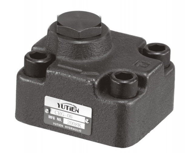
BLINCE's current hydraulic valve range lists the CRG Series Pilot Operated Check Valve, and the live catalog points to the CRG Series product page. That product correspondence is Published. The exact CRG model's pilot ratio, cracking pressure, permitted working pressure, port arrangement, seal material, flow capacity, pressure-drop curve, and certification status are Unknown / confirm by datasheet for this article. None of the numerical examples below should be read as a CRG specification.
The operating principles and equations are based on published technical documents from Danfoss and Parker. They explain the engineering method, but a machine builder still has to apply the selected component's data, the machine manual, applicable standards, and a risk assessment. A valve choice alone does not certify a lifting function or make a suspended load safe.
The Two Valves Do Different Work
A pilot-operated check is a released lock, not a lowering control
A pilot-operated check uses a check element, commonly a poppet, to allow flow in one direction and block reverse flow. Pressure at a separate pilot port mechanically opens the check when reverse flow is required. Danfoss describes this type of valve as a way to positively hold a pressurized load and release it with a pilot signal in its Pilot Operated Check Valves Technical Information.
That behavior is essentially on/off. Below the release condition, the valve remains seated. Once sufficient pilot force overcomes load pressure, cracking pressure, spring force, geometry effects, and relevant backpressure, the valve opens. It is useful for a clamp, outrigger, fixture, or cylinder that must stay put after the directional valve is centered, provided the circuit does not rely on this opening event to meter a gravity-driven load smoothly.
The low-leakage seat can improve static holding compared with depending only on directional-spool clearance. It does not repair a leaking cylinder seal, eliminate thermal expansion, or make an unsuitable directional center compatible. If the machine's symptom is drift, the first job is to identify the leakage path; the BLINCE guide on how to separate cylinder leakage from valve leakage covers that diagnostic task in more detail.
A counterbalance valve is a pilot-assisted relief with a bypass check
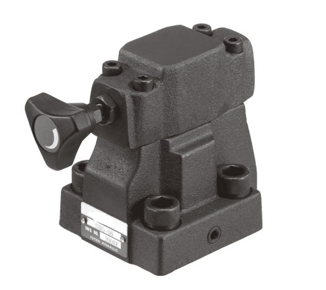
A counterbalance valve, also called an overcenter valve in many applications, combines a pilot-assisted relief function with an integral bypass check. Free flow can enter the actuator through the check path. Flow leaving the loaded actuator is held back by the relief section and is progressively enabled by the pilot signal. Danfoss's Motion Control Valves application information describes its jobs as holding the load, preventing runaway, and metering load-driven outlet flow.
That metering function is why a counterbalance valve is normally the better starting architecture for a vertical cylinder lowering a gravity load or an overcenter boom whose linkage can drive the actuator. The valve maintains resistance at the outlet instead of merely switching from closed to open. Selection and adjustment still matter: a setting that is too high wastes pressure and produces heat, while a setting or pilot ratio that sacrifices too much control margin can allow unstable motion.
The integral check does not make the valve a complete parking brake, a personnel-lift safety device, or a substitute for a mechanical support. Hose-failure protection depends on the valve being at or within the actuator, the plumbing between valve and actuator, its model rating and capacity, the installation, and the machine-level safety design.
A directional spool is not automatically the load-holding device
A closed-center symbol can look like four blocked ports on a schematic, yet spool valves normally have internal clearance and their real behavior includes leakage, pressure trapping, and transient pressure. Treating the spool alone as a rated load lock can lead to drift or an unintended release path. A separate load-holding valve is selected according to the required leakage performance and machine safety architecture.
There is another complication with a pilot-operated check. Danfoss cautions that a closed-center directional valve may trap pressure in the pilot line. If that trapped pressure is high enough, the check can remain piloted or open when the designer expects it to be seated. The center condition must give the pilot circuit a suitable path to depressurize, while still satisfying the rest of the machine's requirements. The symbol, pilot routing, and measured pressure matter more than the label “closed center.”
The Selection Question: Does the Load Drive the Motion?
Start with the actuator during the commanded movement, not during neutral. Ask which pressure source causes motion. If pump flow has to push the actuator throughout the stroke and the load resists that motion, the valve may only need to hold position after the command ends. If gravity, inertia, or linkage geometry can make the load force oil out of the actuator faster than the pump fills the opposite chamber, the circuit has an overrunning-load problem.
An overrunning load can create a gap between actuator demand and supplied flow. The load accelerates, inlet pressure falls, the valve reacts, and the cylinder alternates between moving and being restrained. A pilot-operated check's abrupt release is poorly suited to controlling this process. A correctly selected counterbalance arrangement meters outlet flow and maintains the resistance needed to keep the actuator under hydraulic control.
Do not decide from cylinder orientation alone. A horizontal cylinder can become overcenter through a linkage, and a nominally vertical cylinder may operate against a load in one direction but be driven by it in the other. The load can also change sign during one stroke. Review the full geometry, worst-case load, speed, and direction rather than writing “vertical equals counterbalance” into a purchasing rule.
Decision Table for a Loaded Cylinder
The table below is a circuit-architecture starting point. “Strong candidate” and “usually preferred” are not approvals for a specific machine; each row includes the information that can reverse the first choice.
Cylinder duty
Pilot-operated check starting point
Counterbalance starting point
What can overturn the choice
Static clamp, fixture, or outrigger with no gravity-driven lowering
Strong candidate for positive on/off holding
Often adds restriction that the duty does not need
Use the table by first identifying the required motion behavior. Then test the candidate against pilot pressure, backpressure, maximum outlet flow, directional center condition, and valve location. If the load can run ahead of pump supply, selecting a pilot-operated check because it has lower pressure loss during normal flow does not remove the need for motion control.
Worked Example: Pilot Pressure for an 80-Bar Cylinder Load
The following calculation shows why bore, rod diameter, and pilot ratio belong in a quotation. Every input in this example is an Example, not a BLINCE product claim.
Assume a double-acting cylinder retracts while the load induces 80 bar on the bore side. The cylinder has a 100 mm bore and a 56 mm rod. The proposed pilot-operated check has an assumed 2 bar cracking pressure and 3:1 pilot ratio.
Ar / Ab = effective rod-end area divided by bore area.
Substitute the example values:
Ppilot = (80 bar + 2 bar) / (3 − 0.686)
Ppilot = 82 / 2.314 = 35.4 bar
The Calculated ideal pilot pressure is therefore about 35.4 bar. This result is not the pressure that should automatically be set on a machine. It is an idealized opening requirement before return backpressure, line loss, friction, dynamic effects, manufacturing tolerance, temperature, and the margin required by the actual circuit are considered.
The 3:1 ratio and 2 bar cracking pressure are Example inputs. Before using this method for a CRG Series Pilot Operated Check Valve, replace them with the selected model's current published data. If the actual ratio is unavailable, the calculation is incomplete rather than “close enough.”
Why the area term cannot be ignored
The pilot signal acts through one chamber while pressure on the other cylinder area contributes to the force balance. Using only 80 / 3 would suggest 26.7 bar and miss both the assumed cracking pressure and the cylinder-area effect. In this example, the full equation gives 35.4 bar. That difference is large enough to explain a valve that releases on an unloaded bench but fails or chatters when installed on the machine.
Rod-side applications require additional care because pressure intensification can make a trapped pressure higher than the pump pressure. Before adding pilot pressure to “force it open,” verify the cylinder geometry, trapped volumes, pressure ratings, and relief paths. The correct response to an unexplained high pressure is measurement and circuit review, not a larger arbitrary adjustment.
Counterbalance Comparison Using the Same 80-Bar Load
Danfoss counterbalance application guidance commonly uses a setting of at least 1.3 times the maximum load-induced pressure as a selection starting point. This factor is Published manufacturer guidance, not a universal machine-safety rule and not a BLINCE setting instruction.
With the Example maximum load-induced pressure of 80 bar:
Starting setting = 1.3 × 80 bar = 104 bar
The Calculated example starting setting is 104 bar. For an idealized counterbalance relationship:
Ppilot = (relief setting − induced load pressure) / pilot ratio
With a 3:1 Example pilot ratio and the full 80-bar induced load:
Ppilot = (104 − 80) / 3 = 8 bar
At near-zero induced load, using the same setting and ratio:
Ppilot = (104 − 0) / 3 = 34.7 bar
Both results are Calculated ideal values. They show a useful, sometimes surprising behavior: the load itself assists opening, so the valve may require less pilot pressure at high load and more pilot pressure at light or no load. A circuit that lowers the rated load acceptably can therefore be slow or fail to open cleanly when the attachment is empty.
Backpressure and dynamic effects can increase the real pilot requirement and change the valve response. The place to confirm those pressures is at the relevant load port, pilot port, and return path during the actual event. BLINCE's guide to where to measure pilot and return pressure explains why a gauge at the pump outlet alone can miss the decisive restriction.
Pilot Ratio Is a Stability–Energy Tradeoff
A higher pilot ratio reduces the pilot pressure needed to open a valve under a given ideal load condition. That can reduce inlet pressure and energy loss. It can also make the valve more responsive to pilot-pressure changes and leave less control margin when the load, linkage, or backpressure varies.
A lower pilot ratio generally requires more pilot pressure and creates more restriction during controlled movement, but it tends to favor stability. Danfoss discusses this selection tradeoff in How to Select a Counterbalance Valve, while Parker's load-control technical information likewise frames lower ratio as more control with more restriction, and higher ratio as lower power demand with less control.
This is not a bigger-is-better parameter. A buyer who changes from 3:1 to a higher ratio only because the existing circuit lacks pilot pressure may be trading an obvious opening problem for poor control under changing load. Review the available pilot pressure, setting, load range, linkage, backpressure, and desired stability together.
Backpressure Can Change an Otherwise Correct Calculation
Return pressure is not necessarily tank pressure. A shared return manifold, undersized hose, cooler, filter, quick coupling, downstream valve, or long pipe can create pressure at the valve outlet. Depending on the valve's internal area relationships and drain arrangement, that pressure can raise the pilot requirement, shift the effective setting, or interfere with stable metering.
Measure during the failing movement and with the oil at a representative operating temperature. A cold no-load shop test can hide a restriction that appears only at full outlet flow, while a hot system can reveal leakage and viscosity-dependent behavior not present at startup. Record steady readings and transients if the instruments allow it; do not reduce a cycling pressure to one guessed number.
Size for Actuator Outlet Flow, Not Only Pump Flow
A cylinder can discharge more oil from one chamber than the pump sends into the other because the two effective areas differ. During retraction, flow entering the smaller annulus side and leaving the larger bore side can produce an outlet-flow multiplier based on the area ratio. Linkage or an overrunning load can add transient demand. The load-control valve has to pass and control the maximum actual outlet flow in the relevant direction.
For the example cylinder, Ab / Ar = 7,854 / 5,391 = 1.457. If a particular motion sent Example pump flow into the annulus side and discharged the bore side without leakage or compressibility effects, the theoretical bore-side outlet flow would be about 1.457 times the inlet flow. This ratio is Calculated from the example geometry; no pump flow or BLINCE valve capacity is being claimed.
Use the selected valve's rated flow and pressure-drop curve, not only its nominal port size. A valve that connects to the hose can still be undersized for controlled outlet flow, creating heat and excessive pressure loss. The exact CRG flow curve is Unknown / confirm by datasheet in this article.
Installation Location Is Part of the Safety Function
A load-holding valve intended to limit load movement after a hose failure should be mounted at or as close as practical to the actuator port, or integrated into the actuator, according to the component instructions and the machine safety design. A valve on a remote manifold leaves the hose and fittings between the actuator and valve outside that protection boundary.
“Mounted near” is not a measurable design requirement by itself. Review the length and failure exposure of the connecting line, port blocks, adapters, tubing, and any volume between the actuator and seat. The selected component's mounting rules and rated conditions remain controlling. Personnel lifting or other safety-critical machinery may require redundancy, velocity-fuse functions, certified devices, mechanical support, or other measures beyond either valve discussed here.
Equipment-Specific Checks That Change the Choice
Static clamps and fixtures
A clamp that closes under pump pressure, remains stationary, and opens only after a deliberate command is a strong pilot-operated-check candidate. Verify that the pilot signal is available in the opening direction and can decay after the command. Also check whether thermal expansion in a trapped volume can raise pressure while the valve is closed. If the fixture must release in a controlled, slow way under stored mechanical energy, the duty is no longer purely static.
Outriggers and stabilizer legs
An outrigger may appear static during work but move under substantial gravity load during retraction. Establish whether pump flow positively drives the whole return movement or whether machine weight can overrun it. Check rod-side intensification, required holding leakage, pilot routing, valve mounting at the cylinder, and any machine-specific safety requirements before treating the leg as a simple clamp.
Vertical presses and lifting cylinders
If the cylinder has to lower a platen or load smoothly, a pilot-operated check should not be assigned the metering job. A counterbalance architecture may be appropriate, but it still needs a setting, ratio, flow rating, and backpressure analysis. If people can enter beneath the load, neither the article nor a catalog selection substitutes for the prescribed mechanical blocking and machine safety procedure.
Booms, platforms, and overcenter linkages
Linkage geometry can cause load-induced pressure to rise, fall, or reverse sign through the stroke. Calculate or measure the worst cases rather than using only the mid-stroke pressure. A lower pilot ratio may give better stability across that changing geometry at the cost of higher pilot pressure and energy loss. Valve location, structural flex, hose compliance, and directional-metering characteristics can also affect oscillation.
Winches and hydraulic motors
Motor and winch load control involves brake release, anti-cavitation, motor leakage, rotational inertia, and bidirectional behavior that do not map directly onto a cylinder example. The separate BLINCE guide to motor and winch overrunning-load control is the more relevant starting point for those systems.
Practical Tradeoffs Before Purchasing
Positive holding versus smooth control
A pilot-operated check offers a direct seated load lock with relatively simple on/off behavior. That is valuable when static holding is the goal. The same abrupt opening is a disadvantage when a gravity load must be lowered smoothly. A counterbalance valve can combine holding with metered release, but it introduces an adjustable relief function, pressure drop, heat, and greater sensitivity to setting, pilot ratio, and backpressure.
Lower restriction versus control margin
Choosing a high pilot ratio or a less restrictive path can reduce the pressure that the pump must develop during movement. The tradeoff is a smaller stability margin when the load changes or the pilot signal fluctuates. Choosing a lower ratio can improve control but require more pressure, consume more energy, and expose a weak pilot source. The useful design point is determined by the complete duty cycle, not by minimizing one pressure reading.
One valve at a manifold versus protection at the actuator
Remote manifold installation can simplify assembly and service access. Mounting a load-control valve directly at the actuator reduces the unprotected fluid path when hose failure is part of the risk assessment. The second choice may demand a cylinder-mounted block, different plumbing, space, environmental protection, and service planning. Cost comparisons that omit this safety boundary are incomplete.
Common Selection and Adjustment Errors
1. Buying by thread size and maximum pressure alone
Matching ports and a headline pressure rating does not establish functional compatibility. Pilot ratio, cracking or setting pressure, controlled-flow capacity, pressure drop, seal material, pilot arrangement, drain condition, mounting, and operating temperature can all change the result. Request the exact symbol and datasheet for the proposed model.
2. Using a pilot-operated check as a meter-out valve
Restricting a line elsewhere does not turn the check into a stable load-control element. It can produce stop-start movement as the pilot condition alternately opens and closes the seat. If the load drives the cylinder, evaluate a counterbalance arrangement and the complete meter-in/meter-out behavior.
3. Adjusting a counterbalance valve by trial and error under a suspended load
Do not turn an adjustment until the movement “looks right” while someone or equipment remains exposed beneath a load. Follow the machine procedure and exact valve instructions, use rated test equipment, support or de-energize the load as required, and measure at the correct ports. The 1.3 factor is a published starting guideline, not permission to improvise a setting.
4. Ignoring the directional-valve center condition
Trapped pilot pressure can keep a pilot-operated check released. A center condition can also block a return path needed for a counterbalance circuit to operate as intended. Read the actual symbol, trace every pilot and drain path, and measure residual pressure after the command returns to neutral.
5. Reading only pump pressure
Pump outlet pressure does not reveal the load-port, pilot-port, and return-line conditions at the valve. A machine can show adequate main pressure while line loss or backpressure prevents release. Place rated test points where the equations and circuit behavior require data.
6. Sizing from pump flow without the cylinder area ratio
The controlled outlet flow can exceed pump flow. If the valve is selected only from pump displacement and speed, the real return flow may place it outside its useful pressure-drop or stability range. Calculate flow from cylinder areas and commanded speed, then check the valve curve.
7. Assuming every drift problem belongs to the holding valve
Cylinder piston-seal leakage, directional-spool leakage, contaminated oil, damaged seats, incorrect pilot pressure, thermal effects, and external leakage can create similar symptoms. Replacing the load-control valve without isolating the leakage path can leave the fault unchanged. The broader check-valve leakage and pilot-release diagnosis provides a separate troubleshooting path.
8. Assuming a valve automatically satisfies hose-failure or personnel-lifting requirements
Protection depends on the complete architecture, location, ratings, installation, applicable rules, and verified failure response. A generic product description cannot approve the machine. Obtain the applicable design requirements and use the machine manufacturer's safety procedure.
Who Should Not Buy or Use a Pilot-Operated Check for This Duty?
Do not choose a pilot-operated check as the primary answer when the cylinder must smoothly lower an overrunning load and the circuit expects the valve itself to meter that outlet flow. It is also a poor purchase when the available pilot source cannot meet the calculated worst-case release pressure, the directional center traps pilot pressure, or no one can confirm the proposed model's ratio and cracking pressure.
A buyer should pause rather than order a CRG model from the family name alone if the application depends on a specific certified safety function, personnel lifting, an unverified pressure or flow rating, a special seal, or a port arrangement not shown in a current datasheet. Those are Unknown / confirm by datasheet items until the exact model is reviewed.
Who Should Not Treat a Counterbalance Valve as the Complete Answer?
A counterbalance valve is not a substitute for a mechanical prop, parking brake, certified personnel-lift device, or the machine's prescribed lockout method. It is also not a sensible automatic replacement for every static load-holding circuit. Where the actuator does not overrun and the primary requirement is low-leakage on/off holding, the added restriction, heat, adjustment work, and cost may provide no useful motion-control benefit.
Do not purchase or adjust one when maximum load-induced pressure, controlled outlet flow, pilot source, backpressure, mounting position, and applicable safety requirements are unknown. An adjustable valve without measured circuit data is not a shortcut around engineering.
Information Needed Before a Technical Review or Quote
A useful quotation starts with a circuit and duty description rather than “need one 3/8-inch load valve.” Submit the following information where available:
Machine type and the cylinder's function.
Cylinder bore, rod diameter, stroke, and orientation.
Load magnitude, direction, and linkage geometry through the full stroke.
Maximum measured or calculated load-induced pressure, with its test location and operating condition.
Pump flow, commanded cylinder speed, and estimated maximum actuator outlet flow.
Existing valve manufacturer, complete model code, nameplate photos, hydraulic symbol, and datasheet.
Required pilot ratio and cracking pressure for a pilot-operated check, or setting range and pilot ratio for a counterbalance valve.
Directional-valve symbol and center condition.
Pilot source, pilot-line routing, and whether pilot pressure is available at light and full load.
Pressure traces at the actuator load port, pilot port, and return port during the symptom.
Hose internal diameter, length, routing, quick couplings, filters, coolers, and other shared return restrictions.
Oil type, hot-oil temperature, cleanliness information, and duty cycle.
The exact symptom: drift rate, hesitation, chatter, uncontrolled lowering, heat, noise, or failure to release.
Valve mounting distance from the actuator and photos of the plumbing between them.
Port standard, mounting envelope, seal requirement, environmental conditions, and electrical/control constraints if relevant.
Machine standard, regulatory requirement, hose-failure requirement, or personnel-lifting status.
If some measurements are unavailable, mark them unknown. That is more useful than substituting a nominal pump pressure or an assumed ratio. It lets the review identify which test point or datasheet is needed before a responsible selection can be made.
FAQ
Can a pilot-operated check valve control cylinder lowering speed?
Not as the primary motion-control device for an overrunning load. Its release is fundamentally on/off: pilot pressure opens the check so reverse flow can pass. Smooth lowering normally requires a circuit that meters load-driven outlet flow, commonly a correctly selected counterbalance valve. Flow controls and directional metering still have to be coordinated with that architecture.
Why can a counterbalance valve need more pilot pressure at light load?
The induced load pressure assists the pilot signal in overcoming the valve setting. In the 104-bar setting and 3:1 example, ideal pilot pressure is 8 bar with 80 bar of induced load but 34.7 bar near zero load. Real requirements can be higher because of backpressure, line loss, friction, and dynamic margin.
Where should a cylinder load-holding valve be mounted?
When the design relies on the valve to limit movement after a hose failure, it should normally be at or within the actuator according to the valve instructions and machine safety design. A remote valve leaves the connecting hose and fittings outside the protected boundary. Confirm location, plumbing, ratings, and applicable machine requirements.
Does a closed-center directional valve work with a pilot-operated check?
It can, but the symbol alone does not prove compatibility. A closed center may trap pilot pressure and unintentionally keep the check open, or it may block a pressure-release path the circuit needs. Trace the pilot path and measure residual pressure in neutral before approving the arrangement.
Can a counterbalance valve replace a mechanical brake or support?
No general claim can be made that it does. A counterbalance valve can hold a hydraulic load and meter an overrunning movement when correctly selected and installed, but it is not automatically a parking brake, mechanical prop, or certified personnel-lift safety system. Follow the machine's specific safety design and procedure.
How do I size the valve when cylinder outlet flow exceeds pump flow?
Calculate the effective cylinder areas and flow in the controlled direction. In the 100 mm bore and 56 mm rod example, Ab/Ar = 1.457, so one direction can theoretically discharge about 1.457 times the inlet flow under the stated ideal relationship. Then check the proposed valve's rated flow and pressure-drop curve with margin for the real duty.
Is 1.3 times load-induced pressure the correct counterbalance setting for every machine?
No. It is published manufacturer starting guidance used in preliminary selection. The exact setting depends on the valve design, load variation, pilot ratio, backpressure, dynamics, machine instructions, and safety requirements. Do not use the factor as a universal field-adjustment rule.
Why does a cylinder chatter after a new pilot-operated check is installed?
Possible causes include insufficient or unstable pilot pressure, an overrunning load, trapped or varying backpressure, line restriction, an unsuitable directional center, and a mismatch between the assumed and actual pilot ratio. Measure the pilot, load, and return pressures during the chatter before replacing another part.
What CRG Series pressure, flow, and pilot ratio should I use?
This article does not publish those model-specific figures. The current BLINCE catalog confirms the CRG Series as a real pilot-operated check product, but the chosen model's pilot ratio, cracking pressure, working pressure, ports, seals, flow rating, and curve must be confirmed from its current datasheet before quotation.
Prepare the Circuit Data Before Choosing the Valve
The decisive split is straightforward: use positive on/off holding for a genuinely static duty, and use metered load control when the cylinder can be driven by its load. The engineering work begins after that split. Calculate pilot pressure from actual cylinder geometry, account for light-load and full-load conditions, measure return backpressure, size for controlled outlet flow, and check how the directional center releases the pilot circuit.
For a BLINCE review, send the machine function, cylinder dimensions, load and linkage information, pressure traces, pump and outlet flow, valve symbol and model, pilot arrangement, hose routing, hot-oil condition, mounting photos, and applicable machine-safety requirements. BLINCE can then compare the duty with the available CRG Series data or identify why a counterbalance or another load-control architecture should be reviewed instead. The response should state what matches, what remains unverified, and which measurement or datasheet is still needed before quotation.
This article is a general engineering guide. Final component selection should be based on machine drawings, measured hydraulic data, working conditions, safety requirements, and confirmation from a qualified hydraulic engineer or supplier.
Blince Hydraulic Team
Blince Hydraulic is an industry-leading company dedicated to precision-engineered fluid power manufacturing and custom hydraulic solutions. Backed by decades of deep field expertise in industrial machinery and thousands of successful global deployments, our engineering team focuses entirely on high-performance hydraulic component manufacturing, including specialized orbital motors, high-pressure travel drives motor, and robust directional control valves. Our production infrastructure utilizes state-of-the-art multi-axis CNC machining systems and is fully ISO 9001 certified to guarantee repeatable volumetric accuracy across every single manufacturing run.
We deliver fast, highly dependable, and cost-efficient hydraulic solutions to heavy industry distributors, machinery OEMs, and maintenance crews across more than 150 countries. Whether your active project calls for a small-volume batch of customized shaft profiles or a large-scale production run of severe-duty cast iron gear pump, we configure our flexible production schedules to meet your target lead times with total pricing predictability. Partnering with Blince means securing maximum system efficiency, elite material quality, and uncompromised fluid power professionalism.
To learn more about our complete product lineup, visit our official website: www.blince.com.