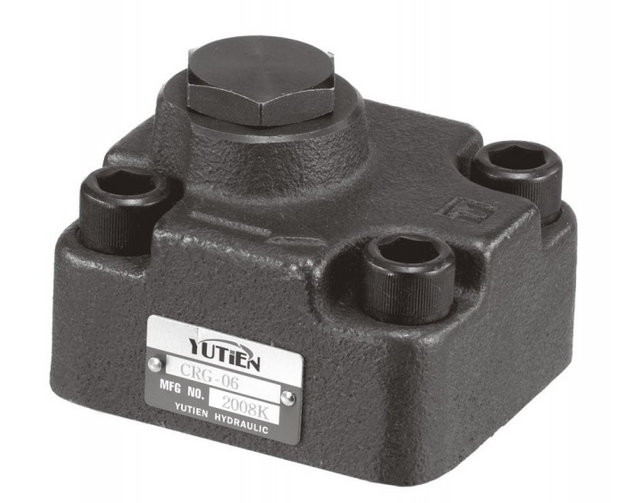
A replacement enquiry often starts with the pump flow. For the worked example here, that would put 30 L/min on the enquiry sheet, comfortably below the proposed valve's 40 L/min listing. The difficulty appears when the sheet also identifies the cylinder and the line containing the check.
The illustrative cylinder has an 80 mm bore and a 48 mm rod. Feed its rod chamber at 30 L/min during retraction and the cap chamber discharges 46.875 L/min. That is the flow reaching a cap-end check. The dimensions and supply flow are chosen inputs for the calculation below; they do not describe a measured repair case.
On the drawing, identify the chamber connected to the check and follow its discharge during the released stroke. This locates the relevant flow duty without assuming that every valve in the circuit carries pump output. Add the pilot source and the free-flow direction to the same sketch. Pressure rating belongs on the specification too, but it cannot supply the missing flow information.
Which flow belongs on the valve specification?
Use chamber discharge to size the released passage, then use load and model-specific pilot data to assess opening. Retraction can send more oil out of a single-rod cylinder's cap chamber than enters its rod chamber. Both requirements belong on the sizing sheet: sufficient passage capacity and an achievable release condition.
Check the load's role before using this as a holding-valve selection method. If the load pulls the piston through the stroke, outlet metering becomes part of the motion-control duty. The pilot check described here opens and closes; it does not continuously regulate that load-driven discharge.
CRG-03 or CRG-06: the first capacity comparison
The CRG listing gives a useful first comparison for this cylinder: CRG-03 at approximately 40 L/min, followed by CRG-06 at approximately 125 L/min. The larger CRG-10 entry is approximately 250 L/min. These entries sit in the hydraulic valve catalog, but the size ladder tells us less than a flow curve would. It identifies capacities to discuss with the supplier. It does not show the pressure loss through the released passage or establish the pilot pressure for an exact ordering code.
Published model
Listed port size
Listed flow capacity
CRG-03
3/8 inch
Approximately 40 L/min
CRG-06
3/4 inch
Approximately 125 L/min
CRG-10
1¼ inch
Approximately 250 L/min
The published pressure limit is 250 bar. For CRG-03, the listing also gives 0.3 MPa pressure drop, but leaves out the flow, direction and viscosity at that test point. That omission matters: there is no curve from which to read the loss at this example's 46.875 L/min. A pressure-drop measurement needs those conditions recorded with it. The pilot-release data and a port drawing are also needed before choosing an exact configuration.
No CRG pilot ratio or operating performance is inferred in the calculations below. The dimensions, flow and pressures used there are labelled Example. Their arithmetic results are Calculated. The actual machine has not been measured, and none of these results is a claim that a particular CRG configuration has passed a circuit test.
Begin with the valve's job during movement
On the schematic, put an arrow beside the check for each stroke. Filling may use the free-flow direction; emptying may require the poppet to be lifted by its pilot piston. This distinction is easy to miss on a purchase order that says only “check valve.” The holding and release functions determine which passage needs a curve. The directional spool's connections determine where the oil and pilot signal come from. With those arrows in place, the buyer can specify a flow direction instead of asking for a valve with a nominal capacity.
A tilting mechanism deserves attention at more than one position. Near one end of travel, the pump may push against the weight; farther along, the same weight may pull the cylinder through its stroke. Once that happens, releasing a lock is insufficient: oil leaving the loaded chamber must be controlled. This is where the choice between a pilot check and a counterbalance valve matters. By contrast, drift after stopping is a holding complaint. A larger pilot check might address a restrictive passage while leaving the change in load direction completely unresolved.
“Valve faulty” leaves too much unsaid. Does the cylinder wait before starting, move slowly after it starts, or creep after the lever returns to neutral? Record the sequence in those terms. A hesitation followed by normal speed differs from poor speed throughout the stroke, and both differ from a stationary load that drifts. Actuator speed diagnosis follows that distinction. For any pressure quoted in the work order, add the test-point location, oil temperature and load condition. Otherwise two apparently conflicting readings may simply describe different points or different moments.
Calculate chamber flow before choosing a body size
The piston moves one distance, but sweeps two volumes. On the cap side it sweeps the full bore; on the rod side it sweeps the bore minus the space occupied by the rod. The latter is the annular area. Bore and rod dimensions on the double-acting cylinder drawing supply the geometry. During retraction, oil enters that smaller area while oil leaves the larger one. The resulting discharge continues through the return hose and its end fittings, so the area ratio belongs in the pipework review as well as the valve calculation.
The effective-area and speed relationships are given in Parker's Mobile Cylinder Products and Application Guide, printed page 16. The calculation below follows one steady retraction stroke in a conventional single-rod cylinder. There is no regenerative connection, accumulator discharge or second branch joining the return. Leakage and oil compression are neglected.
Example inputs: bore diameter D = 80 mm; rod diameter d = 48 mm; rod-end inlet flow during retraction Q_in = 30 L/min.
For this stroke, 46.875 L/min is the discharge requirement. Extension gives a different result even with the same 30 L/min inlet flow: 30 × A_a/A_b = 19.2 L/min leaves the rod chamber. Put the two discharge values beside their respective return paths on the directional circuit. Any cooler in those return paths must accommodate the flow reaching it. This is why an apparently satisfactory extension test cannot establish the capacity of the retraction route.
At 46.875 L/min, the example is already beyond the approximately 40 L/min published for CRG-03. There is no remaining flow allowance to argue about: the original 30 L/min comparison used the wrong chamber flow. CRG-06 is the next size worth discussing, subject to its curves and release data. Changing size may also mean changing the connecting assembly. A quick coupler with a matching thread can still leave a narrow passage in that assembly; replacing the check does not enlarge everything downstream of it.
Rod diameter is worth retaining on the enquiry even when bore and pump flow are already known. Reducing the rod diameter leaves more annular area and reduces the ratio between cap discharge and rod supply. A speed restriction may also reduce the actual cylinder inlet flow below nominal pump output. Elsewhere in the machine, returns may join. Locate those junctions on the directional circuit before specifying a cooler downstream. The flow at the junction includes the discharges arriving there during the operating sequence, which may differ from the flow through an individual check.
Flow capacity and release pressure are separate checks
The released valve has to pass oil, but first the pilot must unseat the check against the forces acting on it. A larger passage cannot compensate for an inadequate pilot signal. Danfoss's Pilot Operated Check Valves Technical Information, printed page PO-5 provides an idealized cylinder-retraction equation. Expressing load force as a load-induced bore pressure gives:
P_pilot = (P_load + P_crack)/(R − A_a/A_b)
Read P_load as external load force divided by bore area. P_crack is the check cracking pressure; R is its pilot ratio. The area term belongs to the illustrated cylinder arrangement. Backpressure is omitted from this Danfoss equation, so an actual valve must be assessed using its own construction and pressure references.
Release calculation, illustrative inputs: keep the 80/48 mm cylinder. Use an external resisting load equivalent to 50 bar on the bore area, a check cracking pressure of 2 bar and a pilot ratio of 3:1. The latter two are assumed valve values. No CRG pilot ratio has been established from the product listing.
The ideal threshold works out to 22.03 bar. At that threshold, the force balance permits release; it provides no result for poppet travel or the passage area available at 47 L/min. To evaluate that operating point, combine the model's opening characteristic with the outlet pressure and its released-flow data.
The source of the load term matters. In this calculation, 50 bar comes from external force divided by bore area. A cap-end gauge reading is taken under the actual circuit condition and can include the effect of pressure on the opposite piston face. Keep that reading with its test condition, rather than substituting it for the external-load term. For pilot-check diagnosis, separate labels for load, pilot pressure and outlet pressure make the record usable. Without those labels, a value such as “50 bar” could refer to several different quantities.
The CRG listing leaves one decisive blank on the sizing sheet: pilot ratio. Without it, the 22.03 bar result remains a hypothetical valve calculation even though the cylinder dimensions are known. The model inquiry therefore needs a released-flow curve and the opening data for the exact code offered. A supplier may instead propose a different function from the valve range. Compare its symbol and operating method with the existing circuit before carrying this equation across. A familiar port layout does not make the old release calculation applicable to the new construction.
Use the return path to explain the remaining pressure demand
Backpressure is pressure at the check outlet, not necessarily pressure near the tank. A spool, hose and coupler can sit between those points; a filter or cooler may add another restriction. When a fault follows an attachment change, compare the coupler's pressure drop under the troublesome flow. When it follows added cooling hardware, compare the cooler's flow and pressure-drop requirements. The 22 bar example contains none of these outlet-pressure effects. The selected valve's pressure references and construction determine how to include them; copying a correction from a different valve would hide that distinction.
Three pressure locations make the release event readable: the cylinder side of the check, the check outlet and the pilot connection. Take the readings during the same movement under the machine's approved test procedure. A remote pump gauge may be steady while pressure at one of those locations changes. Mark the measurement points on the schematic, then trace the active spool passage between them. The useful comparison is local and simultaneous. Comparing a pilot reading at idle with a loaded outlet reading gives no dependable account of the opening event.
Temperature belongs beside the readings, not in a separate comment that says “tested OK.” Cold oil may impose more flow resistance; warm operation may expose leakage that a brief cold test missed. Repeat the relevant observation at the condition where the complaint occurs, following the machine's limits. The cooler and return circuit may impose a flow constraint, while leakage causing cylinder drift calls for a different investigation. A dry rod and a running cooling fan tell little about either internal path. Comparing the same load at unlike temperatures can make a sound valve appear inconsistent.
A decision table for the replacement order
Use this table after calculating the actual chamber flow. Its choices describe the next review step, not a final component approval.
Finding
Candidate action
Benefit
Cost or limitation
Confirmation needed
Example return flow near 47 L/min against CRG-03's listed approximately 40
Pause direct CRG-03 order; investigate a larger configuration
Spool symbol, pilot drain path, neutral pressure record
The larger body has to fit somewhere. Check clearance for the fittings, room for tightening them and access to the pilot port before accepting a drawing. The revised hose assembly specification should include those details, not just the larger thread. There is also a hydraulic tradeoff: changing pilot ratio changes the release requirement. Where the load pulls the cylinder, that easier opening may still leave the motion-control function unresolved. Neither a conveniently sized body nor a low opening threshold establishes stable lowering. They answer different parts of the design review.
Check neutral behavior before calling the selection complete
After checking release, look at what the circuit does when the lever is centered. Danfoss warns that a closed-center arrangement can trap pressure and keep a pilot check open. The concern is visible in the neutral spool connections: a pilot line may have no suitable depressurization path. If the cylinder subsequently creeps, residual pilot pressure belongs in the holding-valve investigation along with leakage. The center-code name alone is too little information. Use the actual symbol and pressure record to establish what remains connected or pressurized after the command ends.
A bench holding test can pass while the installed valve remains piloted in neutral. On the schematic, trace how the pilot line depressurizes after the command ends and whether another function can pressurize it again. A pressure record at the pilot port taken in neutral will show something a coil-click test cannot. For a CRG product inquiry, request the port map before adding or rerouting any drain connection; a port shown on another manufacturer's valve is not evidence that the same connection exists here.
Equipment checks that change the flow screen
For a short-stroke clamp, note the interval between commanding release and seeing the first movement. A restricted passage or release problem may produce a hesitation that is easy to miss in the total cycle time. Once movement begins, record whether speed remains low. Those observations separate initial release from travel-speed performance. After the clamp stops, compare any position drift with the specified holding requirement. “Works slowly” can describe several events in that sequence; the timing record lets the reviewer decide which measurement is missing.
A shared return and an individual holding valve can have different flow requirements. Start at the cylinder, calculate its chamber discharge, then follow that discharge to each junction where another branch enters. The directional circuit shows which branches can operate together; the return assembly drawing shows which pipe segments carry their sum. Note branch flow and combined flow separately. Sizing from pump output divided by cylinder count ignores both the cylinder area ratios and the operating sequence. A large common hose, by itself, supplies no capacity evidence for the branch check.
On an outrigger or raised structure, draw the hose between cylinder and holding valve at its actual location. A remote manifold leaves that hose on the cylinder side of the valve seat, where it remains relevant to load holding. The holding and motion-control arrangement also has to suit the load over its travel. Flow calculations cannot establish the required response to a hose failure. The machine review must address the actual mount, intervening plumbing and consequences of a loss of pressure, including any required mechanical support or approved lowering provision.
Support and isolate the machine by its prescribed service procedure before disturbing a loaded hydraulic connection. Trapped pressure can remain behind a closed check. Loosening a pilot fitting to test release can move the load; use the approved test points and procedure instead. Personnel-lifting duties also require the machine's approved holding and lowering arrangements.
Purchasing mistakes that create a second repair
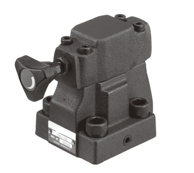
Retaining the old thread may avoid rebuilding the connecting pipework. Preserve that benefit where possible, while comparing the mounting face, sealing details and pilot passage on the drawings. Include these in the connection specification, alongside the proposed valve function. Exterior photographs can identify markings and packaging; the internal symbol establishes how the release operates. A differently shaped body may retain that function, while a familiar-looking replacement may change it. Record both comparisons before treating the connection match as evidence of compatibility.
When movement begins only after pilot pressure increases, record the release event with the local pressure readings. It is evidence about opening demand, rather than a new permissible setting for the machine. Extra supply pressure may still be pushing oil through a restrictive outlet path. Test the pressure drop across a suspect coupler or connection during the same commanded movement. Hold the load and oil-temperature condition comparable between observations. A changed flow rate changes the pressure loss too, making unlike tests a poor basis for judging the effect of an adjustment.
If the first replacement leaves the complaint unchanged, revisit the original measurement record. Neutral drift calls for holding and leakage diagnosis; slow travel after normal release calls for flow-control investigation. Check whether the record actually captured the event that prompted the repair. Replacing a check cannot repair a leaking piston seal, and opening up a passage cannot supply absent pilot pressure. Cooling hardware may reduce oil temperature while the same pressure loss continues to generate heat. Establish which mechanism remains before specifying another component.
Who should pause the order
The missing item on an order may be a drawing rather than a larger model number. When chamber flow or pilot connection is unidentified, the CRG inquiry needs bore and rod dimensions, the complete code and a schematic before a match can be established. When load direction changes over the stroke, the unresolved item is the choice of holding or motion-control function. A sharper photograph may settle a port marking or nameplate suffix. It will not show what the load does as the linkage crosses its turning point.
Prepare a quote request that can be reviewed
Group the information around the holding and release duties:
Machine: equipment function, cylinder orientation and linkage, load direction through the stroke, target cycle and required holding behavior.
Flow: bore, rod and stroke dimensions; supply flow to each chamber; simultaneous functions; calculated maximum flow through each valve path.
Pressure: load condition, cylinder-side and downstream pressure, pilot pressure during release and neutral, working temperature and measurement locations.
Product: complete old code, port markings, mounting face, dimensions, connection/seal standard, current drawing and any cracking-pressure option.
History: whether the complaint is drift, delayed release, unstable movement or heat; what changed; cold/warm comparison and available measurements.
For this calculation, the performance line on the enquiry would be: “80/48 mm single-rod cylinder; check in the cap-end line; rod supply 30 L/min on retraction; calculated cap discharge 46.875 L/min.” Add a request for the quoted code's released-flow curve, pilot ratio, cracking-pressure option, port map and mounting drawing. Attach the load case and local pilot/outlet readings. This example line is ready to replace with the machine's actual dimensions and flow; the assumed inputs should not appear as measurements.
Questions that remain before ordering
Can a 40 L/min valve serve a pump that supplies 30 L/min?
The illustrated cylinder discharges 46.875 L/min from its cap end during retraction. That exceeds a 40 L/min listing even though rod-end supply is 30 L/min. Repeat the area calculation for a different rod diameter or check location; the result, rather than pump output alone, belongs against the relevant flow curve.
Does CRG-06 automatically replace CRG-03?
The higher listed capacity makes CRG-06 worth investigating for the example. The outstanding items are the mounting interface and opening data for the complete code offered. Those data must suit the existing circuit, including its pilot source and return conditions; the series size alone does not establish substitution.
Is the listed 0.3 MPa pressure drop usable at every flow?
The listing gives 0.3 MPa without the accompanying flow direction, flow rate and viscosity. A pressure-drop curve would let the buyer locate the required flow; this isolated value does not. Request the curve or a documented point at the proposed condition before using it in the loss calculation.
Can a larger pilot check make gravity-driven lowering smooth?
Enlarging the passage can reduce flow resistance, but the check still releases as an on/off device. For gravity-driven travel, assess how the circuit meters oil out of the loaded chamber. That motion-control requirement remains after the passage-size problem has been addressed.
Why is full-opening pressure different from first release?
First release corresponds to overcoming the closing forces. The valve may still need more travel to provide the passage area required at operating flow. Use the opening characteristic and flow curve together to establish that condition; the threshold calculation supplies only the starting point.
What if the cylinder still drifts with the correct valve size?
Check the pressure remaining at the pilot connection in neutral, then investigate leakage through the check and cylinder using the machine's approved procedure. An adequate flow capacity establishes neither reseating nor the leakage path. Drift can remain after a successful flow-size correction.
Send the geometry and circuit with the model request
For a CRG inquiry, send BLINCE the complete valve code or marked photographs, cylinder bore and rod dimensions, direction-specific flow, load condition, local pilot and downstream pressures, oil temperature and circuit drawing. These data support a preliminary size screen and identification of missing release or interface information before quotation. Final suitability depends on the selected model's confirmed documentation and the machine's engineering review.
This article is a general engineering guide. Final component selection should be based on machine drawings, measured hydraulic data, working conditions, safety requirements, and confirmation from a qualified hydraulic engineer or supplier.
Blince Hydraulic Team
Blince Hydraulic is an industry-leading company dedicated to precision-engineered fluid power manufacturing and custom hydraulic solutions. Backed by decades of deep field expertise in industrial machinery and thousands of successful global deployments, our engineering team focuses entirely on high-performance hydraulic component manufacturing, including specialized orbital motors, high-pressure travel drives motor, and robust directional control valves. Our production infrastructure utilizes state-of-the-art multi-axis CNC machining systems and is fully ISO 9001 certified to guarantee repeatable volumetric accuracy across every single manufacturing run.
We deliver fast, highly dependable, and cost-efficient hydraulic solutions to heavy industry distributors, machinery OEMs, and maintenance crews across more than 150 countries. Whether your active project calls for a small-volume batch of customized shaft profiles or a large-scale production run of severe-duty cast iron gear pump, we configure our flexible production schedules to meet your target lead times with total pricing predictability. Partnering with Blince means securing maximum system efficiency, elite material quality, and uncompromised fluid power professionalism.
To learn more about our complete product lineup, visit our official website: www.blince.com.